F. Non-Contact Voltage Detector (NCV) (see page 24)
G. Flashlight (see page 19)
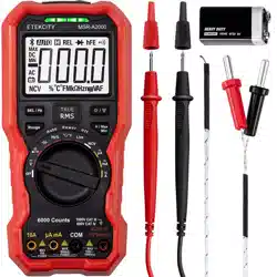
Accessories
H. 9V 6F22 Battery (Pre-Installed)
I. Test Leads
J. K-Type Thermocouple
Rotary Switch
Keypad
Display Screen
Measurement Units
Input Terminals
Operation
Getting Started
Before first using your multimeter, follow these steps to check the instrument:
1. Check for any damage caused by transportation.
If the packaging carton or the foamed plastic protection cushion have suffered serious damage, do not throw them away until you finish testing the multimeter and its accessories to make sure they are working correctly.
2. Check the Accessories
Check the Package Contents (see page 3) and the Diagram (see page 9) to make sure all accessories are correctly included. If any accessory is lost or damaged, please contact Customer Support (see page 38)
3. Check the Multimeter
If you find damage to the appearance of the multimeter, the multimeter does not work normally, or the multimeter fails in the performance test, please contact Customer Support (see page 38).
Install the Batteries
Follow the steps below to install the battery.
Ensure that the rotary switch is at the position. Remove test leads and any connectors from the input terminals.
Lift the tilt stand and loosen the screws with a suitable Phillips-head screwdriver and remove the battery cover.
Observe the battery polarity markings indicated inside the battery compartment. Insert the battery according to the polarity markings.
Place the battery cover back in its original position and tighten the screws.
Adjust the Tilt Stand
Pull the tilt stand outward to its maximum reach (about 85° to the meter body). [Figure 1.1]
Power On
To power ON the multimeter, turn the rotary switch to any other position except OFF.
To power OFF the multimeter, turn the rotary switch to the OFF position.
Sleep Mode
The multimeter automatically enters sleep mode if the rotary switch is not moved or a key is not pressed for 30 minutes.
Pressing or turn the rotary switch will turn the multimeter back to operation mode from the sleep mode.
One minute before Auto Power-Off, the buzzer will beep five times to warn the user that the multimeter is about to shut off. Before shutoff, the buzzer will emit a long beep, and then the multimeter will shut off.
Note: In sleep mode, the multimeter will still use a little power. If the multimeter is not going to be used for a long period of time, the rotary switch should be turned to the OFF position.
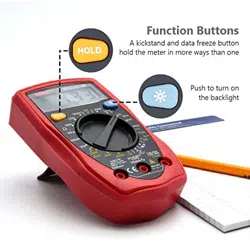
LCD Backlight and Flashlight
When the key is pressed briefly, the LCD backlight will be turned on. This is useful for testing at night or in low-light conditions. After the backlight is turned on, it will automatically turn off after about one minute. To turn the backlight off manually, press the key.
When the key is pressed and held for about 2 seconds, the flashlight will turn on. This is also useful for testing at night or in low light conditions. To manually turn the flashlight off, press and hold the key for 2 seconds.
Selecting the Range
• Auto-ranging mode is set as the default mode when the meter is powered on. will be displayed.
• When auto-ranging mode is enabled, press to enter the manual-range mode.
• In manual range mode, each additional press of sets the multimeter to the next higher range, unless it is already in the highest range, at which point the range switches to the lowest range.
• When manual range mode is enabled, press for more than 2 seconds to enter the auto-ranging mode.
Taking Measurements
Measuring AC or DC Voltage
This multimeter displays DC voltage values as well as their polarity. Negative DC voltages will display a negative sign on the left of the display.
Rotate the rotary switch to . Default is DC measurement mode, and DC will be displayed. Press to switch into AC measurement mode, and AC will be displayed.
Connect the black test lead to the COM terminal and the red test lead to the terminal.
Probe the test points and read the display. Press to enable and cycle through the manual ranges.
Measuring Resistance
Rotate the rotary switch to
Connect the black test lead to the COM terminal and the red test lead to the terminal.
Probe the test points and read the display. Press to enable and cycle through the manual ranges.
Testing for Continuity
Rotate the rotary switch to . Press once to enter continuity testing mode, and will be displayed.
Connect the black test lead to the COM terminal and the red test lead to the terminal.
Probe the test points to measure the resistance in the circuit and read the display. If the reading is below 50ꭥ, the multimeter will beep continuously, and the green indicator light will stay on.
Testing Diodes
Rotate the rotary switch to . Press twice to enter diode testing mode, and will be displayed.
Connect the black test lead to the COM terminal and the red test lead to the terminal.
Connect the red test lead to the positive terminal (anode) of the diode and the black test lead to the negative terminal (cathode). The cathode of a diode is indicated with a band.
Read the diode forward bias. If the test lead connection is reversed, the multimeter will display “OL”.
Multimeter Features
Data Hold Mode
Press to freeze the display during measurement, and will be shown on the display.
Press again to exit this mode.
Capturing Max. and Min. Values
Long press the key to enter the maximum measurement mode, and will appear on the display. Long press the key again to enter the minimum measurement mode, and will display on the display.
Long press the key again to exit the mode. In this mode, the manual range mode will be activated automatically.
Buzzer Feature
• Press the function key, and the buzzer will emit a short beep.
• One minute before Auto Power-off, the buzzer will beep five times to warn the user that the multimeter is about to shut off. Before shutoff, the buzzer will emit a long beep, and then the multimeter will shut off.
• The buzzer beeps continuously to warn the user once the measured DC voltage exceeds 1000V, or the measured AC voltage exceeds 750V.
• The buzzer emits a long beep when the short circuit resistance is less than about 50ꭥ during the continuity test.
Test Lead Insertion Detection Function
• In the non-current function, when a test lead is inserted into or input terminal, the multimeter will sound an alarm and display “LEAD” on the display.
• In thecurrent function, when the test lead is inserted into theinput terminal, the multimeter will sound an alarm and display “LEAD” on the display.
• In the or current function, when the test lead is inserted into the input terminal, the multimeter will sound an alarm and display “LEAD” on the display.
Care & Maintenance
Cleaning
To clean the multimeter exterior, follow these steps:
Wipe the dust from the multimeter surface with a soft cloth. Avoid scuffing the screen when cleaning the LCD. Clean the multimeter with a wet soft cloth that is not dripping water. Scrub with soft detergent or fresh water. To avoid damage to the multimeter, do not use any corrosive chemical cleaning agent.
Dirt or moisture in the terminals can distort readings. Follow the steps below to clean the multimeter terminals.
Turn the multimeter off and remove the test leads.
Turn the multimeter over and shake out the dirt in the terminals.
Wipe the contacts in each terminal with a clean swab dipped in alcohol.
Technical Specifications
All these specifications apply to the multimeter unless otherwise explained.
Standard conditions: The environment temperature is 18°C to 28°C, and the relative humidity is less than 80%.
Note: When measuring AC voltage/current or capacitance, accuracy guarantee range is 5% to 100% of the range.
[1] When measuring current, for 8A to 10A, the measuring duration should not be over 2 minutes within a 10-minute time period, and in this 10-minute time period, no other current should flow through except within the measuring duration.
[2] When measuring capacitance, for the 60.00mF range, the measuring duration should be over 30 seconds.
[3] When measuring frequency, the typical waveform is Square or Sine. The signal meets the following conditions.
[4] When measuring duty cycle, the typical waveform is Square.
Note: When measuring resistance and capacitance, the influence of the resistance reactance of the pen itself on the measured value should be considered.
Interval Period of Adjustment: One year is recommended for the calibration interval period.
If you really need to measure extremely low resistances accurately, you can get a power supply that you can set for a constant current of 1A, and put it through your test load. Then put your meter in the DC millivolt range and read across the load. It will display the resistance in millohms, so a reading of 100 mV would correspond to 0.1 ohms. Few people need to measure such small resistance values, but some specialized things like coils and inductors have test specifications down in those ranges.


 or turn the rotary switch will turn the multimeter back to operation mode from the sleep mode.
 key is pressed briefly, the LCD backlight will be turned on. This is useful for testing at night or in low-light conditions. After the backlight is turned on, it will automatically turn off after about one minute. To turn the backlight off manually, press the
 will be displayed.
 to enter the manual-range mode.
 . Default is DC measurement mode, and DC will be displayed. Press to switch into AC measurement mode, and AC will be displayed.
 terminal.
 once to enter continuity testing mode, and
  will be displayed.
 . Press
  will be displayed.
  to freeze the display during measurement, and
  will be shown on the display.
 will display on the display.
 or
or input terminal, the multimeter will sound an alarm and display “LEAD” on the display.
 current function, when the test lead is inserted into the
 or
or  current function, when the test lead is inserted into the