The ranges must only be used with the legs properly installed.
Before installing the legs, position the appliance near its final location as the legs are not suitable for moving the appliance over long distances.
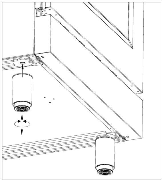
Four height-adjustable legs are shipped with the range in the polystyrene container situated over the appliance.
After unpacking the range, raise it enough to insert the legs in the appropriate receptacles situated on the lower part of the appliance. Lower the range gently to keep any undue strain from legs and mounting hardware. If possible use a pallet or lift jack instead of tilting the unit.
Adjust leg height to the desired level by twisting the inside portion of the leg assembly until the proper height is reached. Check with a level that the cooktop is perfectly level.
WARNING:
A child or adult can tip the range and be killed; Re-engage the anti-tip device if the range is moved. Failure to do so can result in death or serious burns to children or adults.
INSTALLING THE ANTI-TIP STABILITY DEVICE
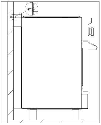
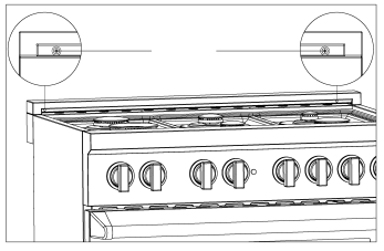
The anti-tip device shipped with the range must be properly secured to the rear wall as shown in the picture below.
The height of the bracket from the floor must be determined after the range legs have been adjusted to the desired height and after the range has been levelled.
Measure the distance from the floor to the bottom of the anti-tip bracket receptacle on the back of the appliance.
Position the two anti-tip brackets on the wall at the desired height plus 1/8" (0.32 cm). The brackets must be placed at 2"5/16 (6,0 cm) from the side of the range. The distance between the two bracket is 25"l/4 (64,1 cm).
Secure the brackets to the wall with appropriate hardware.
Slide the range against the wall until the brackets are fully inserted into their receptacles on the back of the ran
Check to see that the Anti-Tip device is installed properly. Then grasp the top rear edge of the range and carefully attempt to tilt it forward. Verify that the Anti-Tip device is engaged.
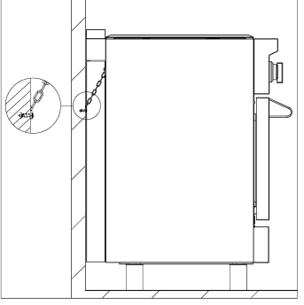
Or use the anti-tip device as one chain, and tighten up with fixed screw on the wall, and when the wall not suitable for installation, the chain shall be fixed to the cabinet structure
The two sides of the chains are fixed on the wall or cabinet structure.
INSTALLATION REQUIREMENTS
ELECTRICAL
A properly grounded and horizontally-mounted electrical receptacle Type NEMA 14-50R should be installed no higher than 3" (7.6 cm) above the floor, no less than 2" (5 cm) and no more than 8" (20,3 cm) from the left side (facing product)
Check all local code requirements
GAS
An agency-approved, properly-sized manual shut-off valve should be installed no higher than 3" (7.6 cm) above the floor and no less than 2" (5 cm) and no more than 8" (20.3 cm) from the right side (facing product).
To connect gas between shut-off valve and regulator, use agency-approved, properly sized flexible or rigid pipe. Check all local code requirements.
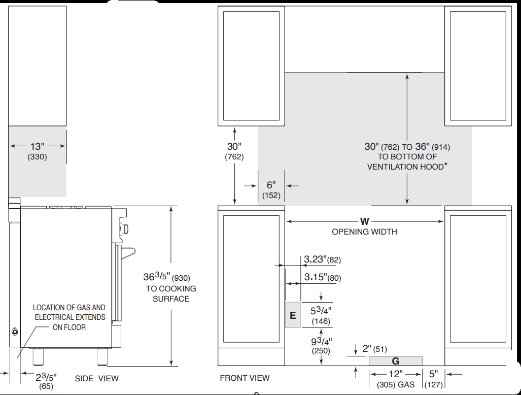
INSTALLATION ADJACENT TO KITCHEN CABINETS
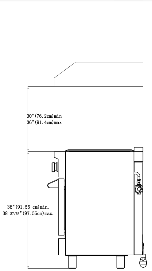
This range may be installed directly adjacent to existing countertop high cabinets (36" or 91.5 cm from the floor).
For the best look, the worktop should be level with the cabinet countertop. This can be accomplished by raising the unit using the adjustment spindles on the legs.
ATTENTION: the range CANNOT be installed directly adjacent to kitchen walls, tall cabinets, tall appliances, or other vertical surfaces above 36" (91.4 cm) high. The minimum side clearance in such cases is 6" (15.2 cm).
Wall cabinets with minimum side clearance must be installed 30" above the countertop with countertop height between 35 " (90.2 cm) and 37 " (94.6 cm). The maximum depth of wall cabinets above the range shall be 13" (33.0 cm)
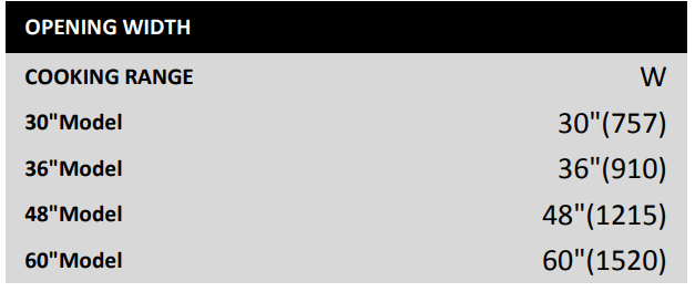
RANGE
EXHAUST HOOD INSTALLATION
To eliminate the risk of burns or fire by reaching over heated surface units, cabinet storage space located above the surface units should be avoided.
If cabinet storage is to be provided, the risk can be reduced by installing a range hood. These hoods have been designed to work in conjunction with the range and have the same finish for a perfect look.
For maximum performance, the height of the bottom of the hood from the worktop should be between 30" (76.2 cm) and 36" (91.4 cm). This would typically result in the bottom of the hood being 61 1/2" (156.2 cm) to 67 1/2" (171.5 cm) above the floor. These measurements provide for safe and efficient operation of the hood.
Before installation of the exhaust hood, consult local or regional building and installation codes for additional specific clearance requirements.
ELECTRICAL CONNECTION
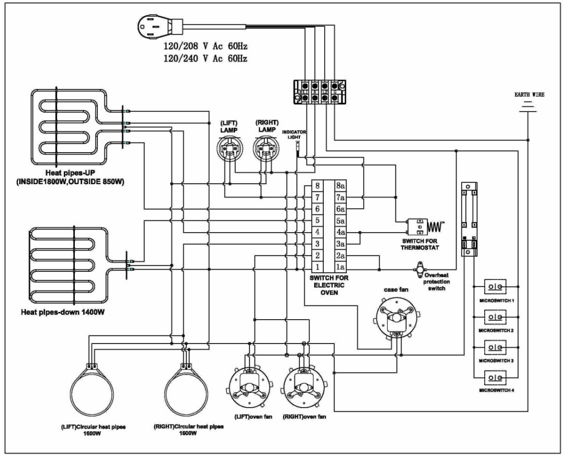
The appliance shall be connected to a single phase electric line rated at 120/208Vac or 120/240Vac and 60Hz frequency.
Electric power rating:
120/208Vac: 10 A max
120/240Vac: 12 A max
Heating elements power rating:
Oven bake element = 1500 Watt
Oven circular element = 3200 Watt
Oven broil element = 2850
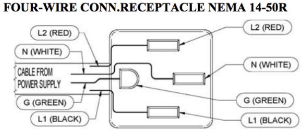
Watt Install a suitable electric power supply receptacle connection type NEMA 14-50R able to support a load of at least 30 A (per line) according to local code requirements. For four wires power supply connection system see diagram below.
Check your local code for which of the options below should be used in grounding the receptacle power suppliy connections.
FOUR Wires connection:
Connect the L1 receptacle terminal to the incoming BLACK electrical supply wire(L1-hot wire)
Connect the L2 receptacle terminal to the incoming RED electrical supply wire (L2-hot wire)
Connect the NEUTRAL receptacle terminal to the incoming NEUTRAL (WHITE) electrical supply wire
Connect the GROUND receptacle terminal to the incoming GROUND (GREEN) electrical supply wire
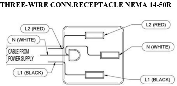
THREE-Wires connection:
Connect the L1 receptacle terminal to the incoming BLACK electrical supply wire (L1- hot wire)
Connect the L2 receptacle terminal to the incoming RED electrical supply wire (L2-hot wire)
Connect the NEUTRAL with the GROUND receptacle terminal to the incoming NEUTRAL (WHITE) electrical supply wire
DO NOT USE EXTENSION CORDS WITH THIS APPLIANCE AS IT MAY RESULT IN FIRE, ELECTRIC SHOCK OR OTHER type of PERSONAL INJURY.
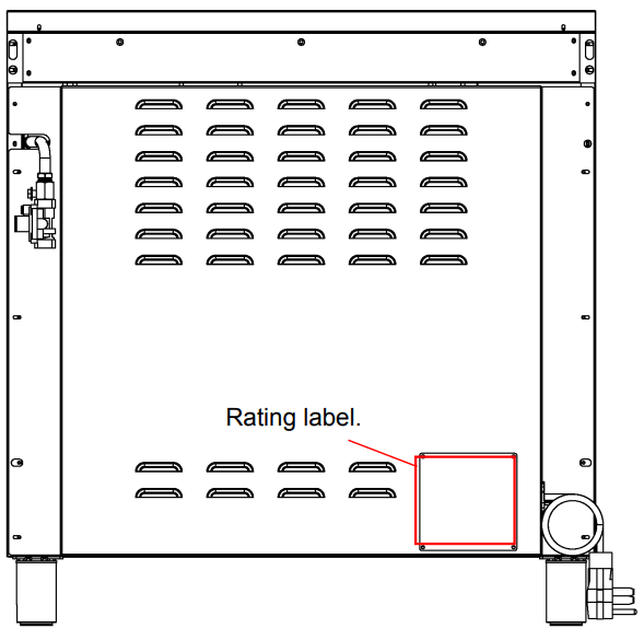
When working with electrical connection, please refer to the rating label, the rating label is located near the entrance of power supply cord.
POWER CORD REPLACEMENT
DO NOT USE EXTENSION CORDS WITH THIS APPLIANCE AS IT MAY RESULT IN FIRE, ELECTRIC SHOCK OR OTHER type of PERSONAL INJURY.
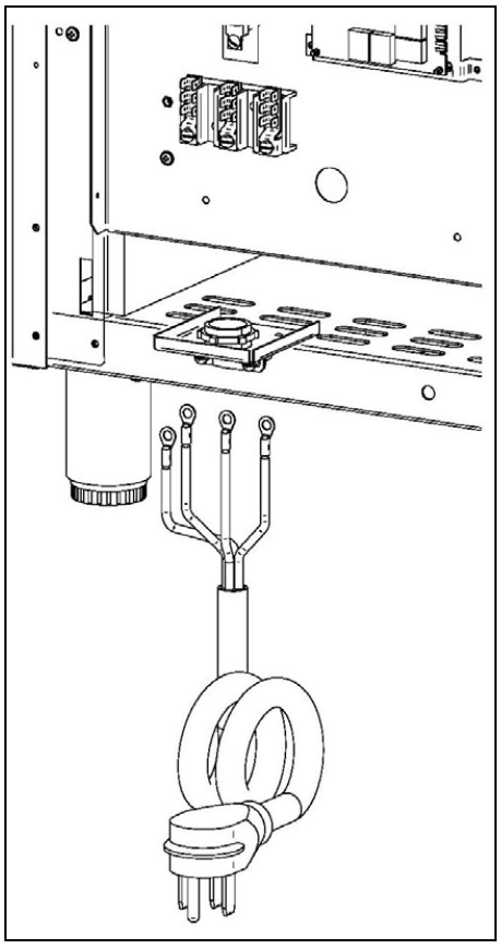
The appliance is equipped at the factory with an electric supply cord set 4 wires type with ring terminals (L1, L2, N, Ground) suitable for range use UL/CSA listed type SRDT/DRT 2x6AWG (L1, L2)+2x8AWG (N, G) rated 300V, 40 or 50A with fused plug type NEMA 14‐50P; cable length 1,5 m.; in case the supply cord set must be replaced, it shall be replaced with an identical set having the same technical specs and following carefully the instructions and diagrams below:
1. Disconnect appliance from electrical power supply receptacle
2. Slide out the appliance from installation place to access to back enclosure panel
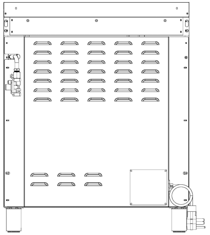
3. Remove back enclosure panel by removing the 6 screws as shown below
4. Loose strain relief by unscrewing the two strain relief's screws as in diagram.
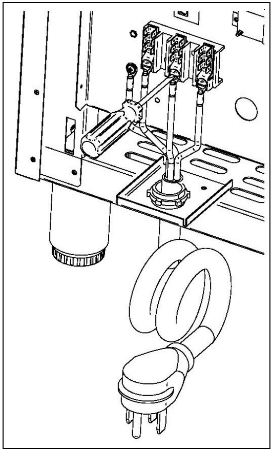
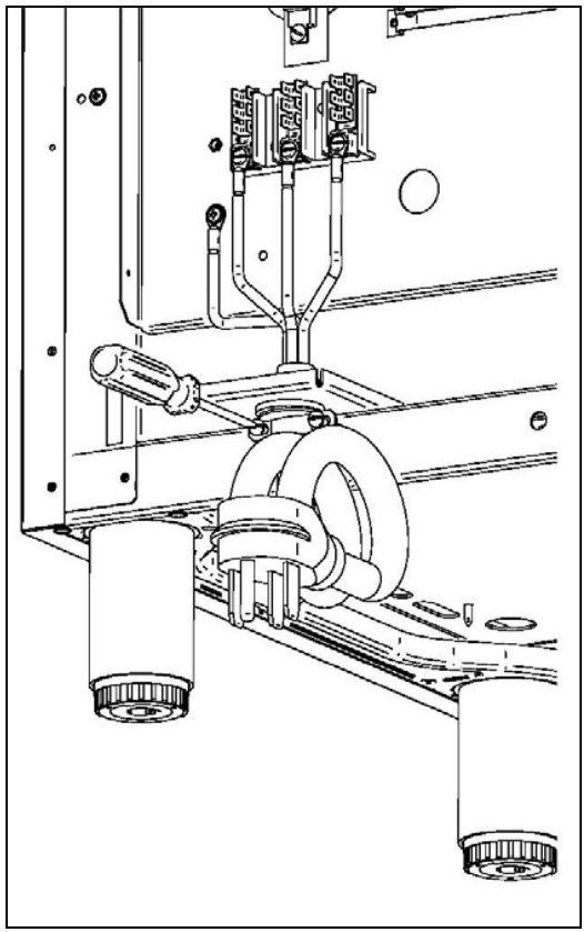
5. Remove damaged supply cord set by taking off the 4 electrical connection screws (block L1, N, L2 and Ground screw, see diagram)
6. Insert the new supply cord set in the strain relief and lock it with two strain relief's screws in suitable position.
7. Fix well the ring terminals G, L1, N, L2 of the new supply cord set as shown in diagram with its 4 screws
8. Re‐install the back enclosure panel with 6 screws
9. Slide the appliance back into its proper location
10. Re‐connect the appliance to the electrical power.
ELECTRICAL GROUNDING This appliance is equipped with a four-prong plug for your protection against shock hazard and should be plugged directly into a properly grounded receptacle. Do not cut or remove the prong from this plug
WARNING! ELECTRICAL SHOCK HAZARD
Disconnect electrical power at the circuit breaker box or fuse box before installing the appliance.
Provide appropriate ground for the appliance.
Use copper conductors only.
Failure to follow these instructions could resilt in serious injury or death
CAUTION
Label all wires prior to disconnecting when servicing controls. Wiring errors can cause improper and dangerous operation.
Verify proper operation after servicing
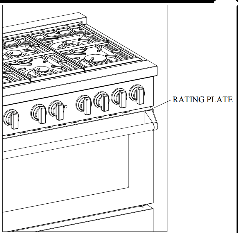
LOCATION OF APPLIANCE PLATES
The data rating plate shows the model and serial number of your range. It is located under the front edge of the range cooktop, and is visible when the oven door is open
A= Rating plate(s) located under front edge of cooktop
B= Wiring / schematic diagram placed on backside panel and on installation booklet
WIRING DIAGRAM
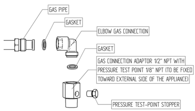
GAS CONNECTION
All gas connections must comply with national and local codes. The gas supply line (service) must be the same size or greater than the inlet line of the appliance. This range uses a 1/2" NPT inlet (see drawing below for details of gas connection). On all pipe joints use appropriate sealant resistant to gas.
This range can be used with Natural or LP/Propane gas. The range is shipped from the factory for use with natural gas.
For LP/propane household installation, the appliance must be converted by the dealer, by a factory-trained professional or by a qualified licensed plumber or gas service company.
Gas conversion is important for safe and effective use of the appliance. It is the responsibility of the dealer and the owner of the range to perform the appropriate gas conversion following the directions of the manufacturer.
THE GAS CONVERSION PROCEDURE IS DESCRIBED IN THIS MANUAL AND IN THE PACKAGE CONTAINING THE CONVERSION NOZZLES SHIPPED WITH EVERY RANGE.
Please provide the service person with this manual before work is started on the range.
WARNING! DO NOT USE AN OPEN FLAME WHEN CHECKING FOR LEAKS!
Leak testing of the appliance shall be conducted according to the manufacturer's instructions. Before placing the oven into operation, always check for leaks with soapy water solution or other acceptable method. Check for gas leakage with soapy water solution or other acceptable methods in all gas connections installed between inlet gas pipe of the appliance, gas regulator, till to the manual shut-off valve.
MANUAL SHUT-OFF VALVE
THIS VALVE IS NOT SHIPPED WITH THE APPLIANCE AND MUST BE SUPPLIED BY THE INSTALLER.
The manual shut-off valve must be installed in the gas service line between the gas hook-up on the wall and the appliance inlet, in a position where it can be reached quickly in the event of an emergency.
In Massachusetts: A T handle type manual gas valve must be installed in the gas supply line to this appliance.
FLEXIBLE CONNECTIONS
In case of installation with flexible couplings and/or quick-disconnect fittings, the installer must use a heavy-duty, AGA design-certified commercial flexible connector of at least 1/2" (1.3 cm) ID NPT (with suitable strain reliefs) in compliance with ANSI Z21.41 and Z21.69 standards.
In Massachusetts: The unit must be installed with a 36" (3-foot) long flexible gas connector.
In Canada: use CAN 1-6.10-88 metal connectors for gas appliances and CAN 1-6.9 M79 quick disconnect device for use with gas fuel.
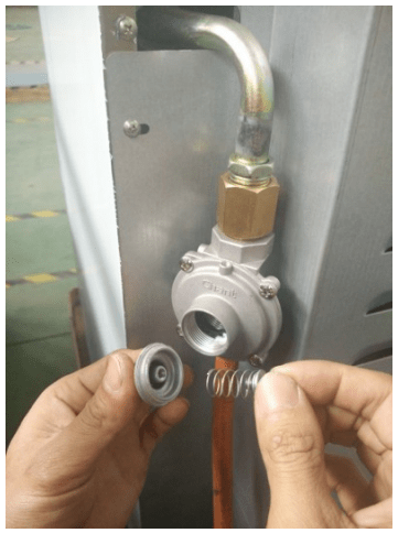
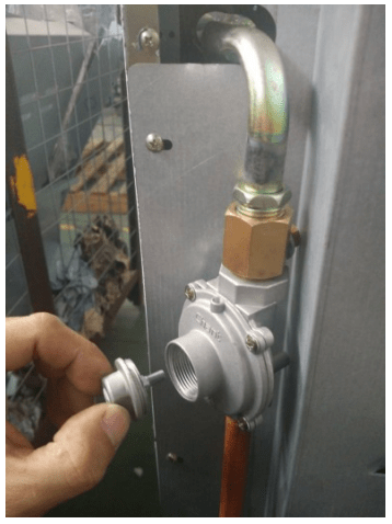
PRESSURE TEST-POINT STOPPED VALVE
To avoid gas leaks, the pressure test-point stopper valve and gasket supplied with the range must be installed on the gas fitting at the back of the range according to the diagram below.
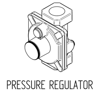
PRESSURE REGULATOR
Since service pressure may fluctuate with local demand, every gas cooking appliance must be equipped with a pressure regulator on the incoming service line for safe and efficient operation.
The pressure regulator shipped with the appliance has two female threads 34" NPT. The regulator shall be installed properly in order to be accessible when the appliance is installed in its final position.
Manifold pressure should be checked with a manometer and comply with the values indicated below:
Natural gas -> 4.0" W.c.P.
LP/Propane -> 10.0" W.C.P.
Incoming line pressure upstream from the regulator must be 1" W.c.P. higher than the manifold pressure in order to check the regulator.
The regulator used on this range can withstand a maximum input pressure of 1/2 PSI (13.8" w.c. or 3,5 kPa) If the line pressure exceeds that amount, a step-down regulator is required.
The appliance, its individual shut-off valve, and the pressure regulator must be disconnected from the gas line during any pressure testing of that system at pressures in excess of 1/2 PSI (13.8" w.c. or 3,5 kPa).
The individual manual shut-off valve must be in the OFF position during any pressure testing of the gas supply piping system at test pressures equal to or less than 1/2 PSI (13.8" w.c. or 3,5 kPa).
APPLIANCE SERVING
Before carrying any service disconnect the appliance from gas appliance from final install have access to the appliance for proper servicing intervention.
GAS CONVERSION WARNING
Before carrying out this operation, disconnect the appliance from gas and electricity.
Gas conversion shall be conducted by a factory- trained professional.
Call the customer service hotline to identify a factory-trained professional near your home.
The gas conversion procedure for this range includes 6 steps:
Pressure regulator
Surface burners
Adjustment of minimum setting
The conversion is not completed if all 6 steps have not been concluded properly.
Before performing the gas conversion, locate the package containing the replacement nozzle shipped with every range. IMPORTANT: Each nozzle has a number indicating its flow diameter printed on the body. Consult the table on page 20 for matching nozzles to burners.
Save the nozzles removed from the range for future use.
STEP 1: PRESSURE REGULATOR
The pressure regulator supplied with the appliance is a convertible type pressure regulator for use with Natural Gas at a nominal outlet pressure of 4" w.c. or LP gas at a nominal outlet pressure of 11" w.c. and it is pre-arranged from the factory to operate with one of these gas/pressure as indicated in the labels affixed on the appliance, package and Instruction booklet.
To convert the regulator for use with other liquid propane LP gas:
1. Unscrew by hand the upper cap of the regulator, remove the white plastic attachment from the cap, reverse its direction and screw it again firmly against the cap. The white plastic attachment has arrows indicating the position for natural gas (NAT) and LP gas (LP).
2. Screw by hand the metal cap in the original position on the regulator
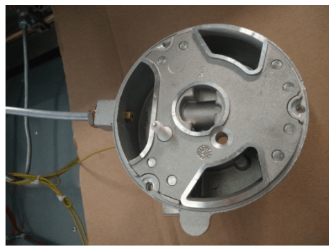
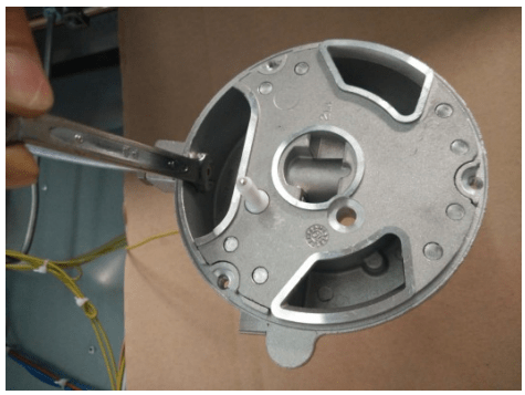
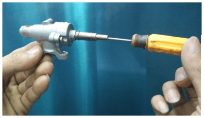
STEP 2: SURFACE BURNERS
To replace the nozzles of the surface burners, lift up the burners and unscrew the nozzles shipped with the range using a 7 mm (socket wrench).
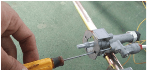
STEP 3: MINIMUM FLAME ADJUSTMENT
WARNING! These adjustments should be made only for use of the appliance with natural gas. For use with liquid propane gas, the choke screw must be fully turned in a clockwise direction.
SURFACE BURNERS
1. Light one burner at a time and set the to the MINIMUM position(small flame).
2. Remove the knob.
3. The range is equipped with a safety valve. Using a small-size slotted screwdriver, locate the choke valve on the valve body and turn the choke screw to the right or left until the burner flame is adjusted to desired minimum.
4. Make sure that the flame does not go out when switching quickly from the MAXIMUM to the MINIMUM position.
Installation Checklist
Is the range mounted on its legs?
Is the back guard securely connected?
Has the anti-tip device been properly installed?
Does the clearance from the side cabinets comply with the manufacturers directions?
Is the electricity properly grounded?
Is the gas service line connected following the directions of the manufacturer?
Have all the proper valves, stoppers and gasket been installed between the range and the service line?
Has the gas connection been checked for leaks?
Has the range been set for the type of gas available in the household?
Does the flame appear sharp blue, with no yellow tipping, shooting or flame lifting?
Has the minimum setting for all burners been adjusted?
Final preparation
All stainless steel body parts should be wiped with hot, soapy water and with a liquid stainless steel cleanser.
If build-up occurs, do not use steel wool, abrasive cloths, cleaners, or powders! If it is necessary to scrape stainless steel to remove encrusted materials, soak with hot, wet cloths to loosen the material, then use a wood or nylon scraper. Do not use a metal knife, spatula, or any other metal tool to scrape stainless steel! Scratches are almost impossible to remove.
Before using the oven for food preparation, wash the cavity thoroughly with a warm soap and water solution to remove film residues and any dust or debris from installation, then rinse and wiped dry.
USER MANUAL
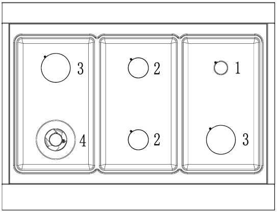
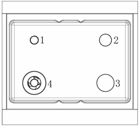
SURFACE BURNER LAYOUT
Small Burner
Medium burner
Rapid burner
Dual burner (Power burner)
SURFACE COOKING
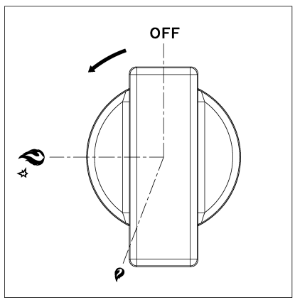
IMPORTANT Take care of reset all worktop/oven/ broiler burners controls in OFF position after use of the appliance.
Burner position (in this case front right burner).
Maximum temperature setting /Recommended control knob position for burner ignition
Minimum temperature setting
SURFACE BURNER OPERATION
ELECTRIC IGNITION
To activate the electric ignition, simply turn the control knob counter-clockwise to maximum power(*position).Press the knob to start the flow of gas and the ignition spark. The spark will released at the metal tip of the white ceramic pin located on the side of the burner. Once the flame is on, release the control knob gently.
If the flame turns off, repeat the above procedure.
ATTENTION: do not ignite burners if the black burner cap is not installed or not centred. The flame will be irregular.
MANUAL IGNITION
Manual ignition is always possible even when the power is cut off or in the event of power failure. Turn the control knob counter-clockwise to the MAXIMUM position. Light the flame with a kitchen lighter or with a match.
TIPS FOR USING BURNERS CORRECTLY
WARNING! Keep children at a safe distance from the appliance during operation. Do not allow children to operate the appliance
IMPORTANT Always make sure to set worktop/oven/broiler burner controls to OFF position after use of the appliance.
1. Always check that the burner caps are properly installed before operation.
2. Verify that the flame of the worktop burners be completely blue and with regular aspect as shown below.
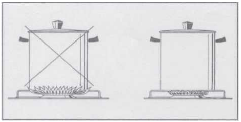
3. Always adjust the burner flame so it does not extend beyond the edge of the pan.
TIPS FOR USING PANS CORRECTLY
ATTENTION!
Always ensure that bottom and handles of pans do not protrude from the worktop.
When cooking with flammable fat such as oil, do not leave the range unattended.
Use pots of the appropriate size on each burner following the indication of the diagram below.
Burner Recommended pan size inches (mm)
Small 3%"-51/2"(90 -140)
Medium 51/2"-101/4"(140 - 260)
Large 71/8"-101/4" (180-260)
Dual burner 82/3"-101/4" (220 - 260)
When boiling liquids, turn the knob to the MINIMUM position once boiling is reached to avoid overflow..
Always use pots with matching lid.
Dry the bottom of pans before operation.
Use pots with a flat, thick bottom (except for wok cooking).
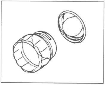
WOK COOKING: always use the wok adapter supplied with the range. Wok pan external diameter shall not be smaller than 10" (25cm) and larger than 16" (40cm).
SIMMERING: use the simmer ring supplied with the range.
OVEN COOKING WARNING!
Use Care When Opening Door. Let hot air or steam escape before removing or replacing food.
Do Not Heat Unopened Food Containers. Buildup of pressure may cause container to burst and result in injury.
Keep Oven Vent Ducts unobstructed.
Placement of Oven Racks. Always place oven racks in desired location while oven is cool. If rack must be moved while oven is hot, do not let potholder contact hot heating element in oven.
Do Not Clean Door Gasket. The door gasket is essential for a good seal. Care should be taken not to rub, damage, or move the gasket
Do Not Use Oven Cleaners. No commercial oven cleaner or oven liner protective coating of any kind should be used in or around any part of the oven.
Clean Only Parts Listed in manual. Before Cleaning the Oven. Remove broiler pan and other utensils.
IMPORTANT In case of electric power failure reset oven/broiler controls in off position and not attempt to use oven/broiler till electric power has been restored.
CAUTION Do not store items of interest to children in cabinets above a range or on the back guard of a range - children climbing on the range to reach items could be seriously injured.
DO NOT TOUCH HEATING ELEMENTS OR INTERIOR SURFACE OF OVEN Heating elements may be hot even though are dark in colour. Interior surfaces of an oven become hot enough to cause burns. During and after use, do not touch, or let clothing or other flammable materials come into contact with the heating elements or interior surfaces of oven until they have had sufficient time to cool. Other surfaces of the appliance may become hot enough to cause burns, for example, oven vent openings and surfaces near these openings, oven doors, oven glass window.
WARNING
TO REDUCE THE RISK OF TIPPING OF THE APPLIANCE, THE APPLIANCE MUST BE SECURED WITH A PROPERLY INSTALLED ANTI-TIPP DEVICES. TO CHECK IF THE DEVICES ARE INSTALLED PROPERLY, REMOVE THE APPLIANCE FROM THE WALL AND THE APPLIANCE FROM THE WALL AND VERIFY THAT THE ANTI-TIP DEVICES ARE ENGAGED
IMPORTANT Make sure to always position worktop/oven/broiler burner controls to OFF position after use of the appliance
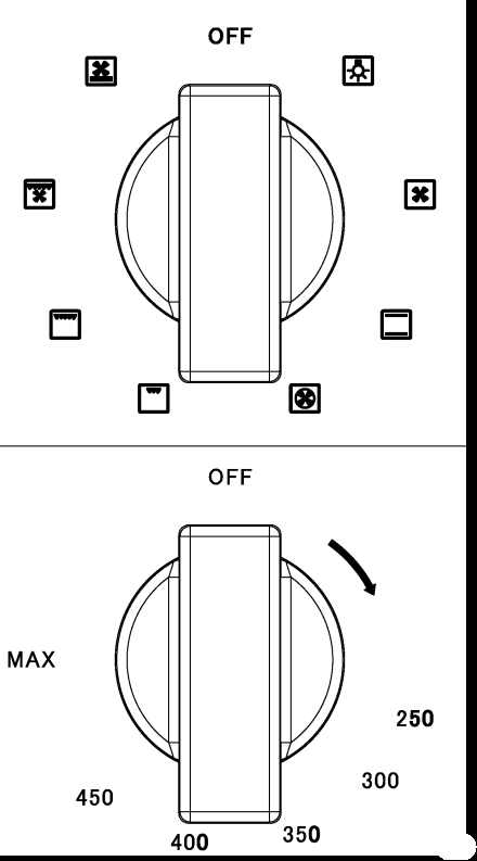
SYMBOLS OVEN FUNCTIONS SELECTOR
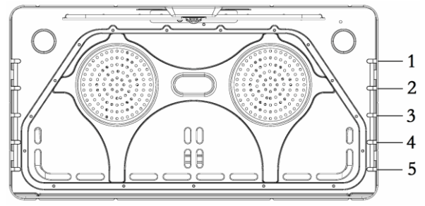
OVEN RACKS
The ranges are equipped with commercial grade shelves and an enamel cooking tray. Shelves are mounted on the appropriate guides situated on the sides of the oven compartment. Insert the shelf between top and bottom guide in any of the 5 positions available.
To keep the oven as clean as possible, cook m on the tray.
When available, always follow recipe book directions. Personal experience will help to determine any variations in the values reported in the table. In any case, it is recommended to follow the instructions of the specific recipe being used.
ATTENTION!
When using the oven for the first time it should be operated for 15-30 minutes at a temperature of about 500°F/260°C without cooking anything inside in order to eliminate any moisture and odours from the internal insulation.
OVEN FUNCTION SELECTOR The oven has 8 functions defined for the following operations (from OFF position in clockwise direction):
BAKE (Broiler + Bottom heating elements) to be used with oven temperature from 100° to 500°F/260°C
TURBO(Circular + Bottom heating elements+ fan) to be used with oven temperature from 100° to 500°F/260°C
BROILER (Broiler heating element) to be used with temperature selector at 500°F for broiling
CONVECTION BROILER (Broiler heating element + fan) to be used with temperature selector at 500°F for convection broiling
CONVECTION (Circular heating element + fan) to be used with oven temperature from 0 to 500°F/260°C
DEHYDRATE (Bottom heating element - fan) to be used with temperature selector at 100°F (corresponding to an internal oven setup fixed temperature of 100°F/38°C)
USING THE OVEN
OVEN LIGHT
The appliance is equipped with two oven lamps that light up when the oven door is opened or each time the oven is in operation. They are turned off during the cleaning cycle.
COOLING FANS
The appliance is equipped with two cooling fan motors that activate when the oven is in operation for cooking or cleaning, except in case of DEHYDRATE and PROOFING functions. In stand-by condition (both selector in OFF position) the cooling fan motors operate if oven temperature exceeds approximately 430°F/220°C and stop automatically when oven temperature drops below approximately 285-360°F/140- 180°C.
FRONT INDICATOR LIGHTS
This appliance is equipped with 3 indicator lights on the front panel:
CLEAN/RED colour: on with door locked during cleaning cycle
HEATING/BLUE colour: on when cooking or cleaning temperature is reached, always on during functions Dehydrate-Proofing-Warming levels 1-2-3
PRE-HEATING/BLUE colour: on during preheating period; not active for functions Dehydrate-Proofing-Warming levels 1-2-3.
The indicator lights flash intermittently (in some case together with the sound buzzer) when an error is detected. For explanation of errors, please refer to the chapter TROUBLESHOOTING GUIDE.
OVEN CONVECTION FAN The appliance is equipped with an oven fan mounted inside a circular heating element, protected by a fan shield on the back of the oven cavity; it operates each time that the oven operates in the functions ROASTING, TURBO, CONVECTION BROILER, CONVECTION BAKE and DEHYDRATE.
BAKE
PREHEATING THE OVEN
Preheat the oven before baking. The oven does not need to be preheated for large pieces of meat or poultry. See your recipe for preheating recommendation. Preheating time depends on the temperature setting and the number of racks in the oven.
GETTING THE BEST RESULTS
Minimize opening the door.
Choose the right size bake ware.
Use the bake ware recommended in the recipe. Store the broiler pans outside the oven: extra pans without food affect the browning and cooking.
Browning can depend from the type of pan used:
For tender, golden brown crusts, use light non-stick anodized or shiny metal pans.
For brown crisp crusts, use dark nonstick/anodized or dark, dull metal utensils or glass bake ware. These may require lowering the bake temperature 25°F.
BAKEWARE TYPE
Metal bake ware (with or without a non-stick finish), heat-proof glass, glass ceramic, pottery, or other utensils are suitable for the oven. Suitable cookie sheets have a small lip on one side only. Heavy sheets or those with lips on more than one side may affect the baking time.
BAKE RACK POSITIONS
ONE RACK BAKING - The Bake mode is best for baking on one rack with rack level 3 and 4 used for most baked items. When baking tall items, rack level 4 may be used. Pies are best baked on rack level 4 or 5 to ensure the bottom of the crust is done without over-browning the top. When large pieces of meat or poultry are roasted such as a prime rib of beef or a turkey, rack level 4 is the preferred rack.
TWO RACK BAKING - Rack levels 3 and 5 may be used when baking on two levels. Cookies and biscuits can be cooked properly using these two racks. Casserole dishes may al so be baked using these two levels.
CONVECTION
COOKING WITH CONVECTION
There are many advantages to cooking with convection. In the convection system, a fan in the back of the oven moves heated air evenly around the oven. The moving air provides even heat so foods can be placed on any rack level with consistent results and without having to rotate the pans. Convection also enables cooking simultaneously on multiple racks.
Low, shallow bake ware should be used with convection cooking. This allows the heated air to properly move around the food. Pans with high sides or pans that are covered are not suitable for convection cooking because high sides or lids prohibit the warm air from circulating around the food
Any food cooked uncovered will brown evenly and form a nice crust. Foods in covered dishes (casseroles, pot roast) or delicate custards are not suitable for convection cooking.
CONVECTION CONVECTION BAKE TURBO
Time can be saved by baking an entire batch of cookies at the same time. The cookies will bake evenly and be done all at once. The baking time may be shorter due to the warm circulating air. For small items such as cookies, check to see if they are done one to two minutes before the recipe time. For larger baked items such as cakes, check five to six minutes before the time indicated on the recipe.
Convection cooking of meat and poultry will result in foods that are brown and crispy on the outside and moist and juicy on the inside. Large meat or poultry items may cook up to 30 minutes less than the suggested time so check them so they will not be over baked. A meat thermometer or an instant read thermometer will provide more accurate results than the "minute per pound" method. The larger the piece of meat or poultry, the more time you will save.
Converting Conventional Baking to Convection Cooking - To convert most recipes for baked items (cookies, cakes, pies, etc.), reduce the oven temperature by 25°F. For meats and poultry, use the temperature recommended in recipes and cooking charts.
CONVECTION BAKE Full power heat is radiated from the bake element in the bottom of the oven cavity and partial power is radiated from the broil element.
Air is circulated by the fan in the rear of the oven. It provides more even heat distribution throughout the oven cavity for all uses. Multiple rack use is possible for baking large amounts of food. When roasting, cool air is quickly replaced - searing meats on the outside and retaining more juices and natural flavour on the inside with less shrinkage
CONVECTION
The rear element operates at full power. Air is circulated by the fan for even heating. Use this setting for food which requires gentle cooking such as pastries, souffles or cakes.
TURBO
The rear and bottom elements operate at full power. Air is circulated by the fan for even heating. Use this setting to reduce pre-heating time of the oven or for recipes which require uniform cooking with strong heat from bottom such as pizza, focaccia bread.
TIPS FOR CONVECTION and BAKE/CONVECTION/TURBO
Preheating the Oven
Preheat the oven before baking. The oven does not need to be preheated for large pieces of meat or poultry. See your recipe for preheating recommendation. Preheating time depends on the temperature setting and the number of racks in the oven.
Temperature Setting
When using Convection Bake, reduce the temperature recommended in the recipe by 25°F. When roasting meats, check internal temperature prior to time recommended by recipe to prevent over cooking. When roasting meats in convection mode, do not reduce temperature setting.
Condensation
It is normal for a certain amount of moisture to evaporate from the food during any cooking process The amount depends on the moisture content of the food. The moisture will condense on any surface cooler than, the inside of the oven, such as the control panel.
RACK POSITIONS
Large Main Oven One Rack Baking When baking on one rack, best results are obtained in the bake mode (see Bake).
When roasting a turkey or a large piece of meat, convection bake may be used. Rack 4 is the most appropriate rack.
Two Rack Baking Racks 4 and 2 are most appropriate when using the convection bake mode. Round cake pans should be staggered on racks 4 and 2. Rectangular (9 x 13) cake pans and cookie sheets should be placed on rack 4 directly under the one on rack 2.
This may be used for cakes, cookies, biscuits and other foods for which two rack baking is desirable. When several casseroles, frozen pies or cakes are to be baked, use racks 4 and 2.
These two racks can also be used for a large oven meal.
Bakeware Type
Aluminium bake ware gives the best browning results.
Cookie sheets with only two sides give the best results. Aluminium commercial half-sheets or professional cooking utensils may be used but baking times may be increased.
Placement
For better browning, utensils such as cookie sheets. Rectangular baking pans should be placed crosswise on the rack with the shorter side facing right and left to allow better air flow.
When baking on more than one rack, cookie sheets and rectangular (9 x 13) cake pans should not be staggered; round cake pans should be staggered.
Settings for BAKE/CONVECTION and BAKE/CONVECTION/TURBO cooking modes
These cooking modes are for baking, roasting or warming using one or two racks.
Select BAKE/CONVECTION or BAKE/ CONVECTION/TURBO using the Selector switch.
Set the oven temperature using the oven temperature control knob (not over Tmax=500*F setting position). If using CONVECTION, set the oven control knob 25°F below temperature suggested in the recipe. Do no change recipe temperature if roasting meats or poultry.
WARMING
SLOW COOKING AND LOW TEMPERATURE USES OF THE OVEN
In this oven function the pre-heating light/sound indicators are deactivated; only the heating indicator light is active.
In addition to providing perfect temperature for baking and roasting, the oven can be used at low temperatures to keep food at the proper serving temperature and to warm plates.
Set the oven to bake and use the suitable temperature.
There are three possible setting for WARMING mode; select in function selector (symbol) and then:
Level 1 with temperature selector set at 200'F (internal oven setup fixed temperature of 140'F=60'C)
Level 2 with temperature selector set at 250° F (internal oven setup fixed temperature of 170° F=77° C)
Level 3 with temperature selector set at 300° F (internal oven setup fixed temperature of 220° F=105° C)
DEHYDRATE
In this oven function the pre-heating light/sound indicators are deactivated; only the heating indicator light is active.
DEHYDRATE mode dries food inside the oven by using lower heating element jointly with the oven fan.
DEHYDRATE is used to dry and/or preserve foods such as fruits, vegetables and herbs through circulation of heated air that slowly remove the moisture from items.
To activate DEHYDRATE mode: set function selector on and set temperature selector at 100°F (corresponding to an internal oven setup fixed temperature of 100°F=38°C).
Cooling fans does not operate during DEHYDRATE.
BROIL / CONVECTION BROIL
Tips for Broiling
Broiling requires constant exposure to high, intense heat. Only the upper element heats in the BROILER mode.
It is recommended that you preheat the broil element before starting to cook. Preheat until the "PRE-HEATING" light turns off (about 5-6 minutes).
Getting the best results
Defrost food before broiling.
Keep oven door closed during broiling. Steaks should be more than 1" thick if rare meat is desired. Use convection broil if steaks are over 1-1/2 inches thick. Turn food over once after half cooking time. It is not necessary to turn very thin food (ham slices, fillets of fish, etc.). Liver slices must be turned over regardless of thickness.
Use a timer. Set it for the minimum time and check the food.
Center food directly under the broiling element for best browning.
Rack Positions
Before turning on the oven, place the rack in the desired position. After preheating the broiler, center the broil pan under the broil element.
2 - Use this rack position when broiling beef steaks, ground meat patties, ham steak and lamb chops 1 inch or less thick. Also use when browning food.
3 - Use this rack position when broiling meat 1 1/8 inches or more thick, fish, poultry, pork chops, ham steaks 1 inch or more thick.
3 or 4 - Use this rack when broiling chicken quarters or halves.
Utensils
A porcelain enamel broil pan is included with the range. Use matal or glass-ceramic bake ware when browning casseroles, main dishes, or bread. DO NOT use hear-proof glass or pottery. This type of glassware cannot withstand the intense hear of the broil element.
Broiling Using Meat Thermometer
To more accurately define the preparation of thick steaks or chops (at least 1 1/2 inches thick), use a meat thermometer. Insert the point of the thermometer into the side of the meat reaching the center of the steak or chop. For rare steaks, cook the first side to 90°F. For medium or well done steaks, cook the first side to 100°F. Turn and cook the second side to desired internal temperature.
SETTING BROILER OR CONVECTION BROILER
Select CONVECTION BROILER to brown food slightly also on the bottom side. This mode is preferred for browning food on both side that is too delicate for turning such as fish. The degree of browning of each side might be different.
TO SET THE OVEN TO BROILER OR CONVECTION BROILER
Place oven rack in desired position.
Set Selector Switch to BROILER or CONVECTION BROILER.
Set oven temperature control knob to BROILER or CONVECTION BROILER setting corresponding to 500° F fixed BROILER setting (not over Tmax=500° F or under 450° F setting position).
Wait until PRE-HEATING light turns off, after approximately 5-6 minutes
Place food in oven at desired rack position.
Close oven door. The door should be closed throughout the broil cycle
MAINTAINING YOUR RANGE
REPLACE THE OVEN LIGHT BULBS
WARNING!
Disconnect power before servicing unit.
To replace the oven light bulb, unscrew the protection cap that projects out inside the oven.
NOTE: Touching the bulb with fingers may cause the bulb to burn out. Always use protective glove or use a cloth to remove the bulb.
CLEANING YOUR RANGE
ATTENTION! During cleaning operation never move the appliance from its foreseen original installation position.
ATTENTION! Never use abrasive cleaners! Scratches on the stainless steel surfaces are permanent.
Do not clean the range when hot!
Cleaning after installation: use a stainless steel cleaning product or wipe to eliminate the glue residues of the blue protection film after removal.
Cleaning the worktop: periodically clean the burner heads, the cast iron pan supports and the burner caps using warm water. Remove burned food and fat residues with a rubber spatula . If food residue prevent the smooth operation of the control knobs, call the customer service hotline to schedule service by a factory-trained professional.
Cleaning stainless steel: for best results use a stainless steel cleaner product with a soft sponge or wipe. Alternatively use a soft sponge or cloth with a warm soap and water solution. Never use abrasive powders or liquids!
Cleaning the burner caps: lift the burner caps from the burner heads and wash them in a warm soap and water solution. Dry thoroughly before using them again. Before reinstalling them on the burner head, check that the gas flow holes are not clogged with food residues or cleaning product residues.
Cleaning Enamel: enamelled parts should be cleaned frequently with warm soap and water solution applied with a soft sponge or wipe. Never use abrasive powders or liquids! Do not leave acid or alkaline substances on the enamelled parts (such as vinegar, lemon juice, salt, tomato sauce, etc.). Use a rubber spatula to remove fat residues.
Cleaning glass door: clean the glass using a nonabrasive sponge or wipe with a warm soap and warm water solution. Use a rubber spatula to remove fat residues.
ATTENTION: while cleaning the door, avoid spillage of food residues and cleaning products in the venting holes situated on the top side of the door. To clean the inside of the oven door, call a factory-trained professional.
ATTENTION: for further details about cleaning of the appliance, please contact your appliance retailer.
TROUBLESHOOTING GUIDE
OVEN PROBLEM
POSSIBLE CAUSES AND/OR REMEDY
Range does not function
Range is not connected to electrical power. Ask a professional to check power circuit breaker, wiring and fuses.
Broil does not work
Temperature control knob is rotated too far past broil position (500° F); PRE HEATING indicator will light intermittently
Door does not open
Oven is still in self-clean mode. Door latch will release when safe temperature is reached.
Oven light does not work
Light bulb is burned out. Range is not connected to power/ clean is cycle on
Igniters does not work
Circuit is tripped. Fuse is blown. Range is not connected to power.
Igniters sparking taut no flame ignition
Gas supply valve is in "OFF" position. Gas supply is interrupted.
igniters spark continuously after flame ignition
ignition micro-switches remain Incorrectly engaged; call a qualified technician for repair.
Burner ignites but flame is targe, distorted, or yellow
Burner ports are clogged. Unit is not set to the appropriate gas type. Call a qualified technician for gas conversion procedure.
Oven door is locked and will not release, even after cooling
Turn the oven off at the circuit breaker and wait 5 minutes. Turn breaker back on. The oven should reset itself and will be operable.
Oven is not heating
Check the circuit breaker or fuse box to your house. Make sure there is proper electrical power to the oven. Make sure the oven temperature has been selected.
Oven light is not working properly
Replace or reinsert the light bulb if loose or defective.
Oven light stays on
Check for obstruction in oven door, Check to see if hinge is bent.
Cannot remove lens cover on light
There may be soil build-up around the lens cover. Wipe lens cover area with a clean dry towel prior to attempting to remove the lens cover.
PRE-HEATING indicator lights up intermittently and sound alarm on
This is a FAULT alarm indicating the failure of the cooling fan/s. Try resetting by turning both selectors to the OFF position. If the error is not repaired, call a qualified technician for diagnosis and repair. If not repaired, this error indicator will appear again within 10 seconds once the oven is activated in any functions for which cooling fans are required to operate, preventing the use of the oven. Set both selectors to OFF position and call a qualified technician for repair.
HEATING indicator light turned on intermittently and with sound alarm on
This is a FAULT indicating failure of the oven sensor temperature probe; in this case cooling fans will start automatically. To reset, switch both selector to the OFF position. To stop buzzer and light indicator, disconnect the appliance from the main electrical supply and call a qualified technician for repair.
CLEAN indicator light on intermittently and sound alarm on
Electrical power failure happening during cleaning cycle operation, cleaning cycle interrupted; cooling fans remains both activated; the error will be reset by putting two selectors in OFF positron; repeat cleaning cycle if needed after 3-4 hours.
CLEAN indicator tight turned on
Interruption/Stop of an incomplete cleaning cycle due to a intentional or
intermittently, sound alarm off
accidental displacement of one of the two oven selectors from CLEAN position during cleaning cycle operation; put both selectors in OFF position, wait that door latch unlocks the door when oven temperature is dropped below 500° F{260° C) and then re-select a desired oven function.
PRE-HEATING indicator light on intermittently, sound alarm on
Wrong temperature knob selection in oven functions BROILER or CONVECTION BROILER (temperature knob positioned not at 500°F position, over Tmax or under 450°F position); select OFF position and then 500°F on temperature selector;
Or
Wrong temperature knob selection for oven functions BAKE, CONVECTION BAKE; TURBO, CONVECTION (temperature knob positioned over Tmax=500°F position); select OFF position and then the desired temperature under Tmax position on temperature selector.
 Burner position (in this case front right burner).
 Maximum temperature setting /Recommended control knob position for burner ignition
 Minimum temperature setting
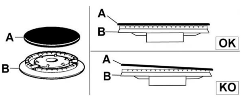
 BAKE (Broiler + Bottom heating elements) to be used with oven temperature from 100° to 500°F/260°C
 TURBO(Circular + Bottom heating elements+ fan) to be used with oven temperature from 100° to 500°F/260°C
 BROILER (Broiler heating element) to be used with temperature selector at 500°F for broiling
 CONVECTION BROILER (Broiler heating element + fan) to be used with temperature selector at 500°F for convection broiling
 CONVECTION (Circular heating element + fan) to be used with oven temperature from 0 to 500°F/260°C
 DEHYDRATE (Bottom heating element - fan) to be used with temperature selector at 100°F (corresponding to an internal oven setup fixed temperature of 100°F/38°C)