Installation Guide & Users
Manual
IMPORTANT: Read and save these instructions.
NOTICE:
Installer: Leave this guide with the homeowner
Homeowner: Keep this guide for future reference
Under Cabinet
Range Hood
¤¨¤ªRange Hood
QB series


This product is designed for indoor residential use only.
USE & CARE
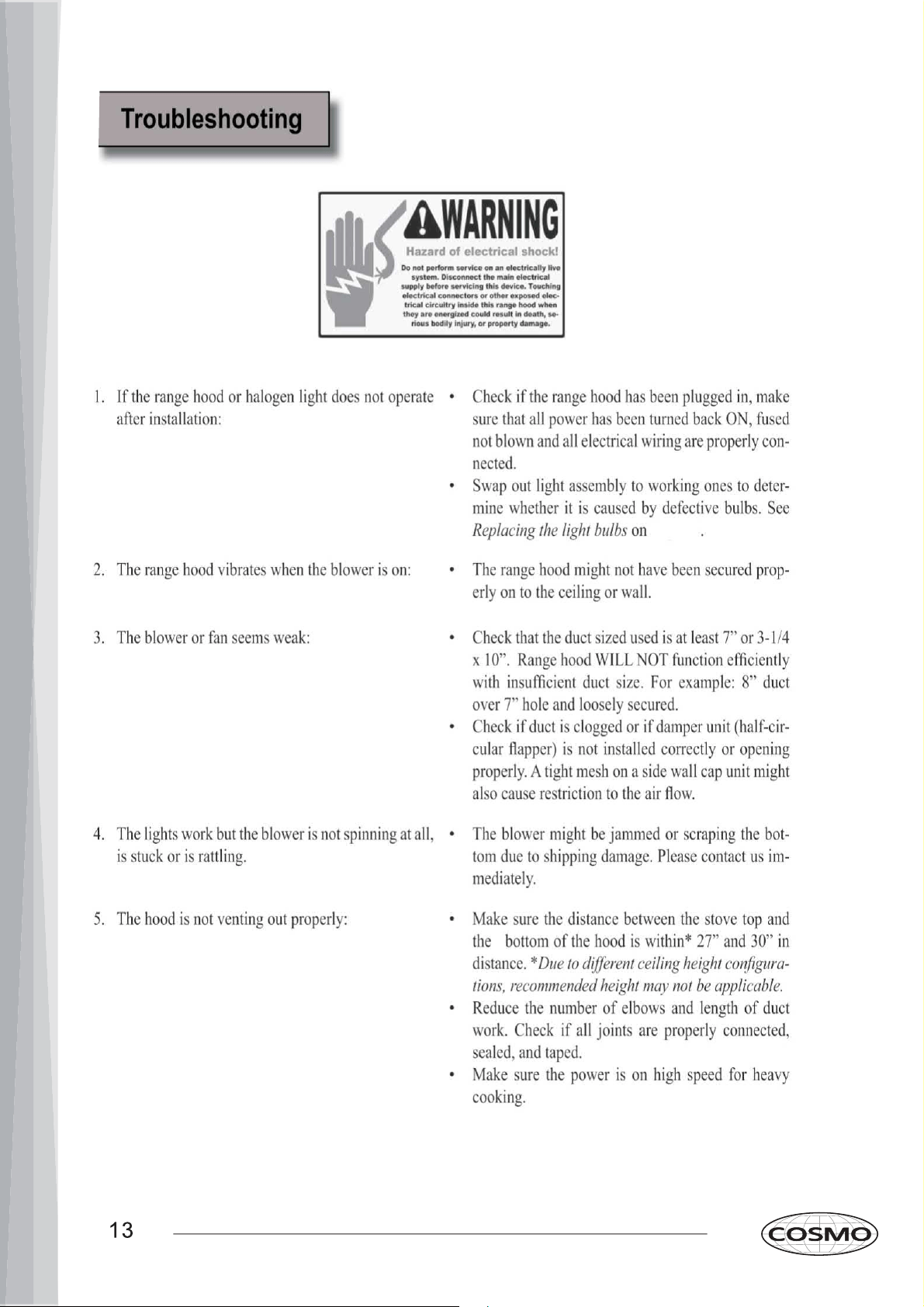
Troubleshooting ..................................13
Use & Care Information .....................14
Measurements & Diagrams ...........15-20
MAINTENANCE
Cleaning ..............................................21
Replacing the Filter ............................21
Replacing the Light Bulb ....................21
WARRANTY & SERVICE
Warranty .............................................22
Contact Us ..........................................23
INSTALLATION
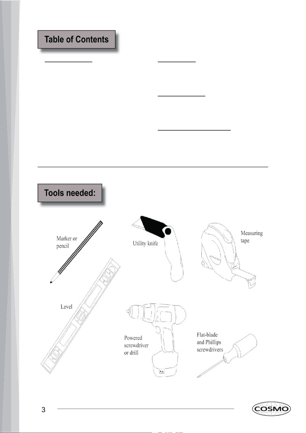
Tools Needed .............................3
Parts Supplied ............................4
Venting Requirements .....................5
Mount Heights & Clearance .........5-6
Calculating Vent System Length .....6
Venting Methods .............................7
Electrical Requirements ...................8
Preparation .......................................9
Installation ................................10-11
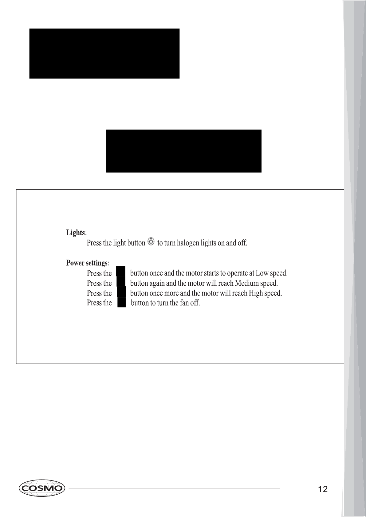
Range Hood Operations .................12
Ceiling
Height
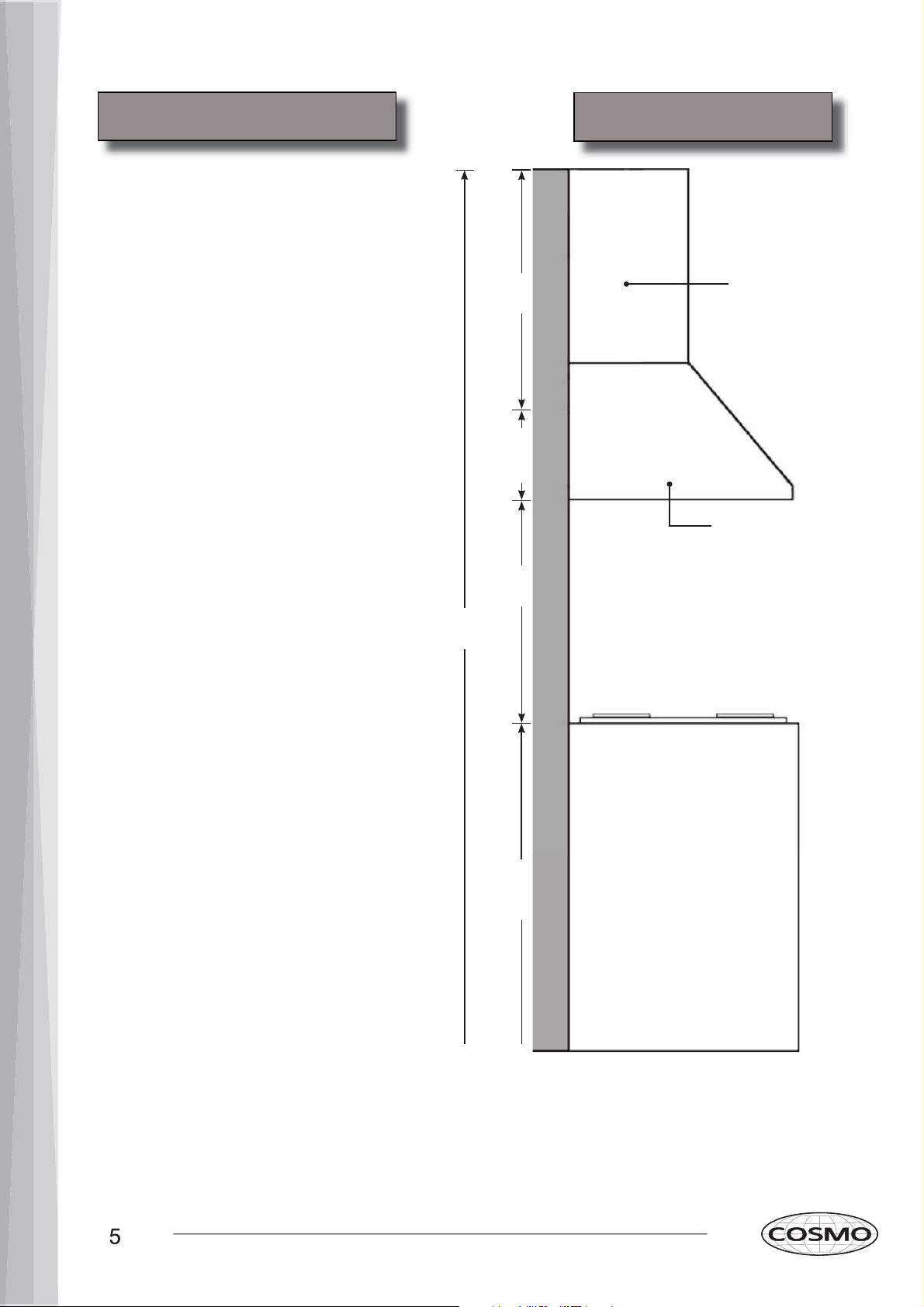
Venting Requirements
Height & Clearance
Under Cabinet
Range hood
36”
Counter
Top
Min:
27”
Max: 30”
Vent system must terminate to the outside •
(roof or side wall).
DO NOT terminate the vent system in an at-•
tic or other enclosed area.
DO NOT use 4” (10.2 cm) laundry-type wall •
caps.
Use metal/aluminum vent only. Rigid metal/•
aluminum vent is recommended.
DO NOT use plastic vent.•
Always keep the duct clean to ensure proper •
airflow.
Calculate the following figures before instal-•
lation:
Distance from the floor to the ceiling.1.
Distance between the floor to the coun-2.
tertop/stove (recommend* 27” to 30”).
Distance between the countertop/stove 3.
to the range hood.
Height of hood and duct cover.4.
For the most efficient & quiet operation:
A distance of 27” to 30” is recommended* •
between stove top and the bottom of range
hood.
It is recommended that the range hood be •
vented vertically through the roof through 8”
(17.8 cm) or bigger round metal/aluminum
vent work.
The size of the vent should be uniform.•
Use no more than three 90° elbows.•
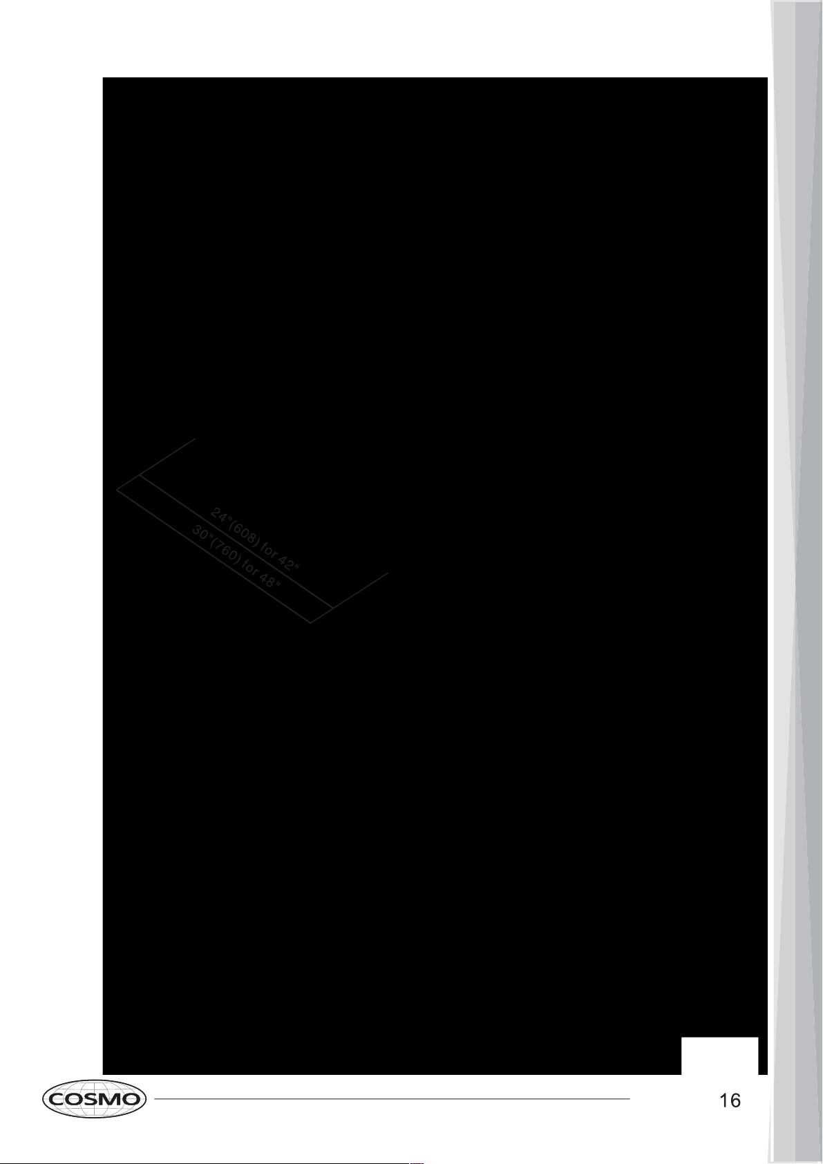
Make sure there is a minimum of 24” (61 •
cm) of straight vent between the elbows if
more than one elbow is used.
DO NOT install two elbows together.•
The length of vent system and number of •
elbows should be kept to a minimum to pro-
vide efficient performance.
The vent system must have a damper. If •
roof or wall cap has a damper, DO NOT
use damper (if supplied) on top of the range
hood.
Use silver tape or duct tape to seal all joints •
in the vent system.
Use caulking to seal exterior wall or roof •
opening around the cap.
Cabinet or Single-
piece Chimney
(Optional)
Range
Hood
Height
Cabinet
Height
Countertop/Stove
IMPORTANT:
A minimum of 8” round (standard for this range hood) or 3-1/4 x 10” rectangular duct (purchased separate-•
ly) must be used to maintain maximum airflow efficiency.
Always use rigid type metal/aluminum ducts if available to maximize airflow when connecting to provided •
duct.
Please use • Duct Run Calculation below to compute total available duct run when using elbows, transitions
and caps.
ALWAYS, when possible, reduce the number or transitions and turns. If long duct run is required, increase •
duct size from 8” to 9” or 10”. If a reducer is used, install a long reducer instead of a pancake reducer. Re-
ducing duct size will restrict airflow and decrease airflow, thus reduce duct size as far away from opening as
possible.
If turns or transitions are required: Install as far away from opening and as far apart, between 2, as possible.•
Minimum mount height between stove top to hood bottom should be no less than 27-inch*.•
Maximum mount height between stove top to hood bottom should be no higher than 30-inch*.•
It is important to install the hood at the proper mounting height. Hoods mounted too low could result in heat •
damage and fire hazard; while hoods mounted too high will be hard to reach and will loose its performance
and efficiency.
If available, also refer to stove top manufacturer’s height clearance requirements and recommended hood •
mounting height above range.
* Due to different ceiling height configurations, recommended height may not be applicable.
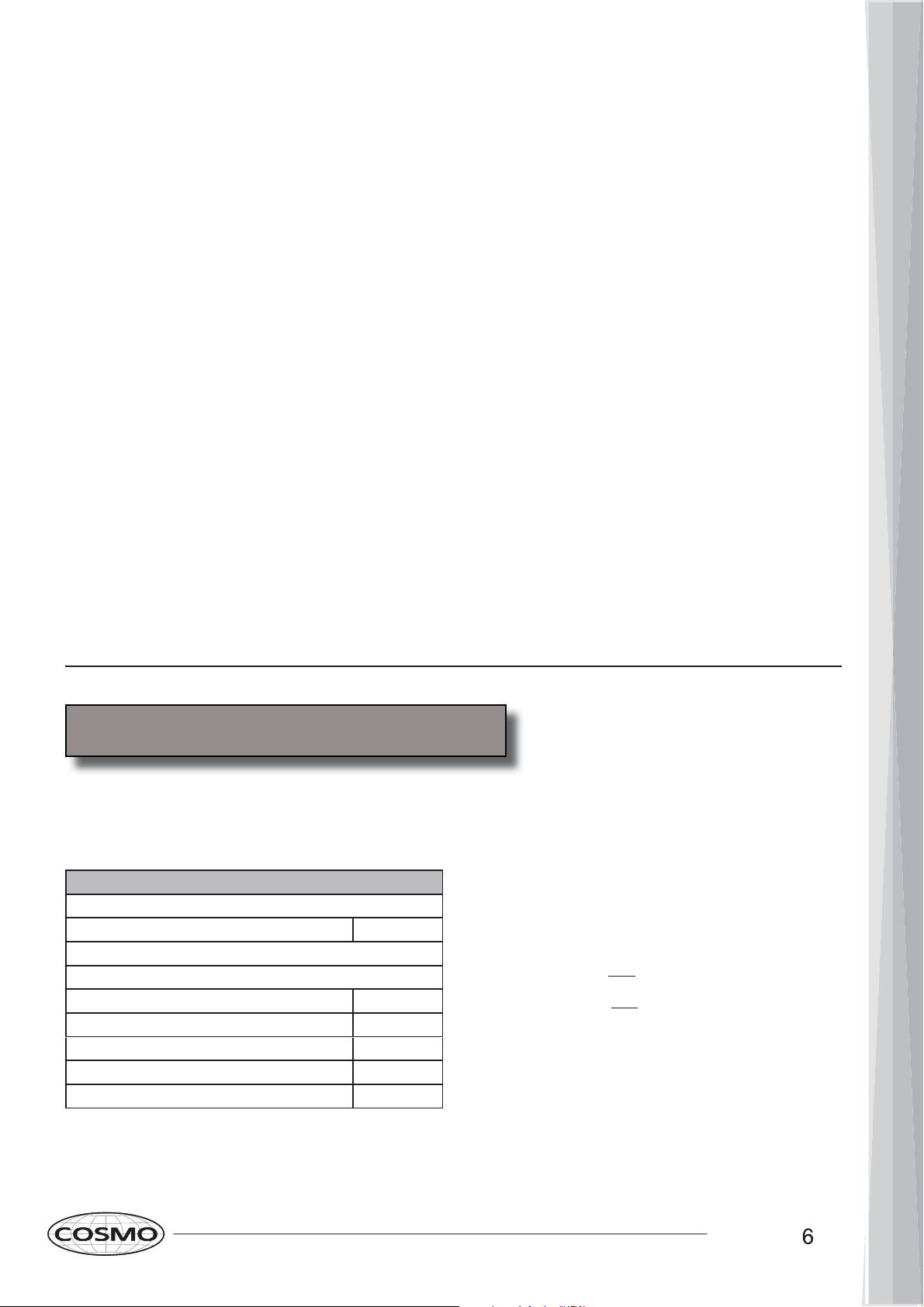
Minimum Duct Size:
Round - 8” minimum•
Rectangular - 3-1/4 x 10” minimum (requires a 8” to 3-1/4x10” adaptor, not supplied)•
Duct Run Calculation:
Recommended maximum run
8” or 3-1/4 x 10” duct 50 ft
Vent piece deduction
Each 90º elbow used 9 ft
Each 45º elbow used 5 ft
Each 8” to 3/14 x 10” transition used 7 ft
Side wall cap with damper 0 ft
Roof cap 0 ft
Duct Run Calcuation example:
One roof cap, two 90º elbow, and one 45º elbow used:
0ft + 9ft + 9ft + 5ft = 23ft used.
Deduct 23ft from 50ft, 27ft maximum available for
straight duct run.
Calculating Vent System Length
To calculate the length of the system you need, deduct the equivalent feet for each vent piece used in the system
from the recommended maximum duct run.

8


Page 21
Operations:
Read and understand all instructions and warnings in this manual before operating the appliance. Save these
instructions for future reference.
Always leave safety grills and lters in place. Without these components, operating blowers could catch on to
hair,
ngers and loose clothing.
NEVER dispose cigarette ashes, ignitable substances, or any foreign objects into blowers.
NEVER leave cooking unattended. When frying, oil in the pan can easily overheat and catch re. The risk of
self combustion is higher when the oil has been used several times.
NEVER cook on “open” ames under the range hood. Check deep-fryers during use: Superheated oil may be
ammable.
Cleaning:
The saturation of greasy residue in the blower and lters may cause increased in ammability. Keep unit clean
and free of grease and residue build-up at all times to prevent possible
res.
Filters must be cleaned periodically and free from accumulation of cooking residue (see Cleaning Instructions
on Page 22). Old and worn
lters must be replaced immediately.
DO NOT operate blowers when lters are removed. Never disassemble parts to clean without proper instruc-
tions. Disassembly is recommended to be performed by quali
ed personnel only. Read and understand all
instructions and warnings in this manual before proceeding.
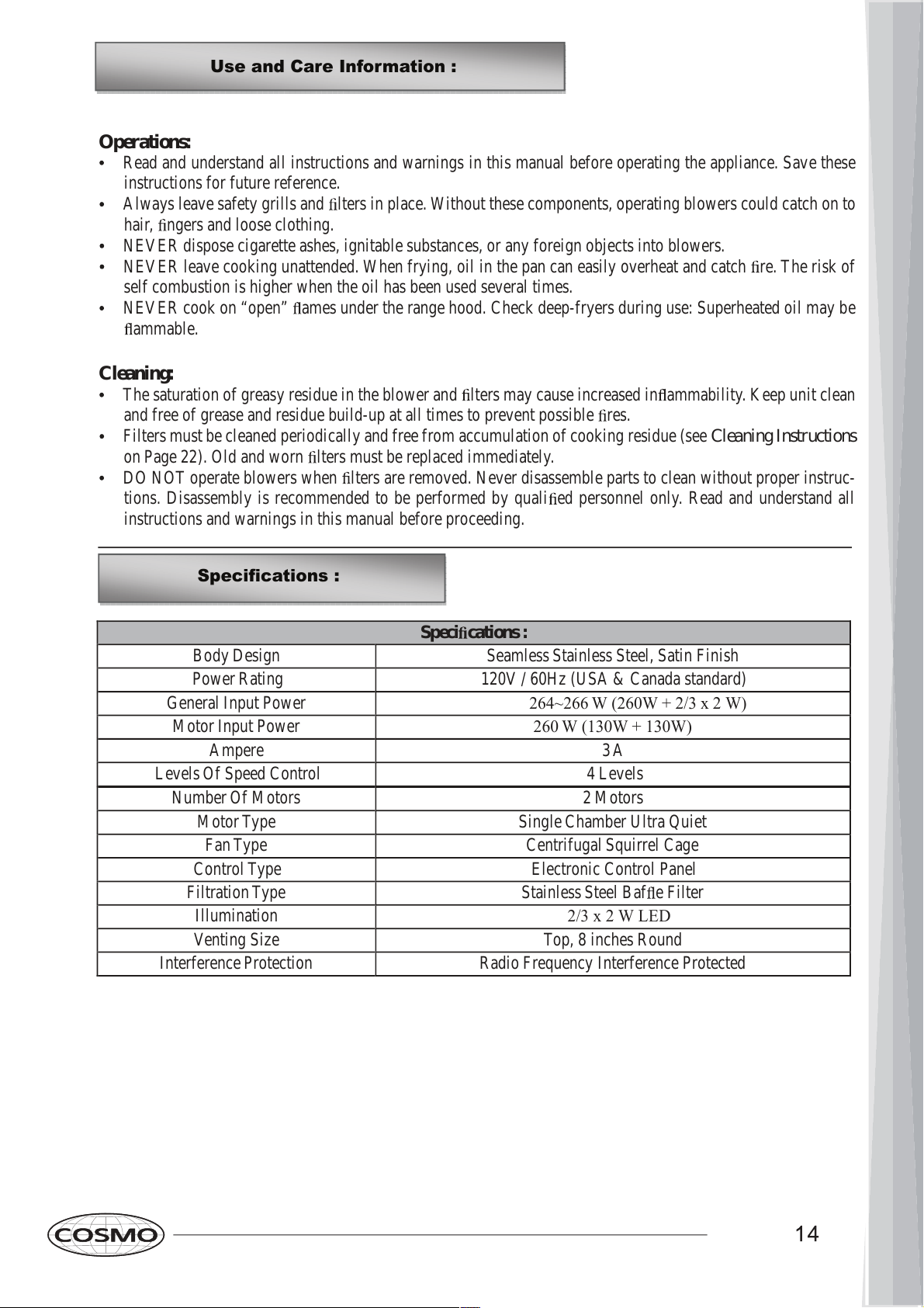
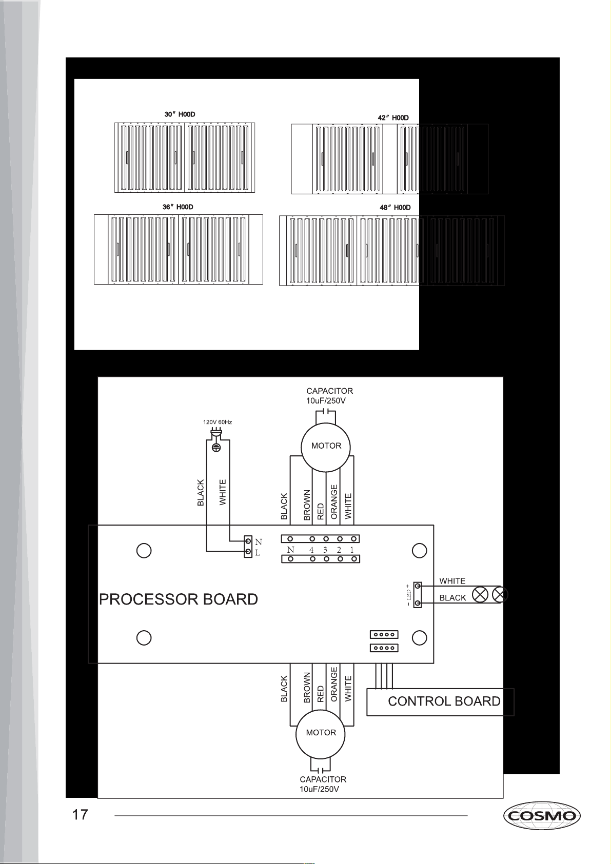
Speci cations :
Body Design Seamless Stainless Steel, Satin Finish
Power Rating 120V / 60Hz (USA & Canada standard)
General Input Power
264~266 W (260W + 2/3 x 2 W)
Motor Input Power
260 W (130W + 130W)
Ampere 3 A
Levels Of Speed Control 4 Levels
Number Of Motors 2 Motors
Motor Type Single Chamber Ultra Quiet
Fan Type Centrifugal Squirrel Cage
Control Type
Electronic Control Panel
Filtration Type Stainless Steel Baf e Filter
Illumination
2/3 x 2 W LED
Venting Size Top, 8 inches Round
Interference Protection Radio Frequency Interference Protected
Use and Care Information :
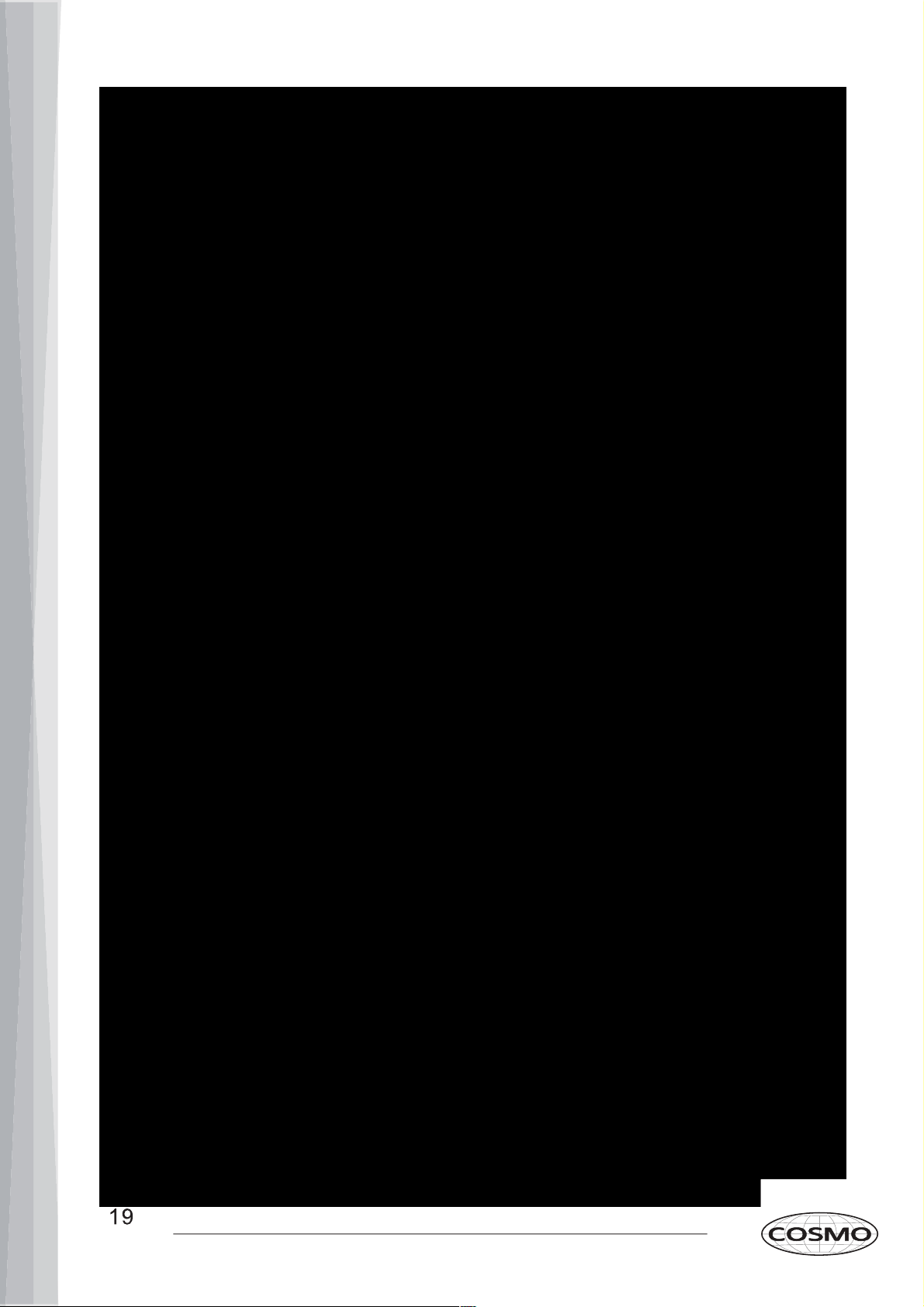
Specifications :
7-3/4
" (197mm)
7-3
/
4" (197mm)
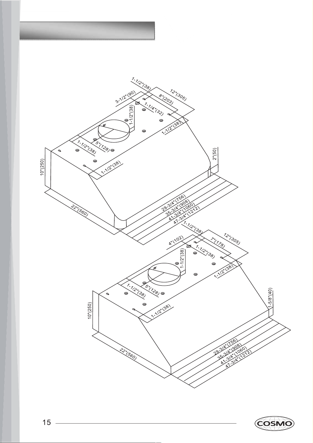
All measurements in parenthesis are in millimeters.
All inch measurements are converted from millimeters, thus inch measurements are estimated.
Measurements and Diagrams :


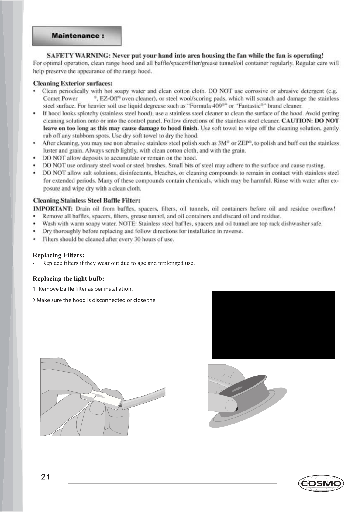
1 Remove bae lter as per installation.
2
Make sure the hood is disconnected or close the
Replacing Filters:
Replace filters if they wear out due to age and prolonged use.•
Replacing the light bulb:
Scrub
circuit breaker.
Reach into the range hood and disconnect power clip.
3 Reach into interior of range hood until touching both lateral clips
located on the side of the puck light. Gently squeeze and push down
until puck pops out from its location.
4
To reinstall new puck light, follow
s
tep 3
in
reverse order.
WARRANTY AND SERVICE
For full warranty details on this product please visit:
http://www.cosmoappliances.com/warranty
TO RECEIVE WARRANTY SERVICE, YOUR
PRODUCT MUST BE REGISTERED. TO REGISTER, VISIT:
WWW.COSMOAPPLIANCES.COM/WARRANTY
SCAN TO REGISTER
Correct Disposal of this product:
This marking indicates that this appliance should not
be disposed with other household wastes. To prevent
possible harm to the environment or human health
from uncontrolled waste disposal, recycle it responsibly to
promote the sustainable reuse of material resources.
IMPORTANT
Do Not Return This Product To The Store If
you have a problem with this product, please contact
Cosmo Customer Support at
+1(888)784-3108
DATED PROOF OF PURCHASE, MODEL #, AND SERIAL #
REQUIRED FOR WARRANTY SERVICE
IMPORTANT
Ne pas Réexpédier ce Produit au Magasin
Pour tout problème concernant ce produit, veuillez contacter
le service des consommateurs Cosmo Customer Support au
+1(888) 784-3108
UNE PREUVE D’ACHAT DATEE EST REQUISE POUR BENEFICIER DE
LA GARANTIE.
IMPORTANTE
No regrese este producto a la tienda
Si tiene algún problema con este producto, por favor contacte el
AYUDA AL CLIENTE COSMO al
+1(888)784-3108
(Válido solo en E.U.A).
NECESITA UNA PRUEBA DE DE COMPRA FECHADA, NÚMERO DE
MODELO Y DE SERIE PARA EL SERVICIO DE LA GARANTÍA
NOTE:

Electronic version of this manual is available at:
www.cosmoappliances.com
Cosmo is constantly making efforts to improve the quality and
performance of our products, so we may make changes to our
appliances without updating this manual.