COS-5U30 INSTALL & USER GUIDE
COS-5U30
INSTALLATION GUIDE
I N S P I R I N G T H E W O R L D ’ S K I T C H E N
IMPORTANT SAFETY INSTRUCTIONS
Carefully read the following Important information redarding installation
safety and maintenance. Keep these instruction for future reference.
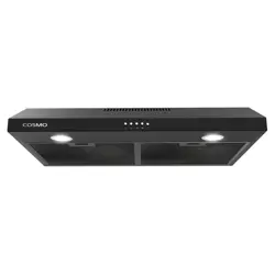
UNDER CABINET RANGE HOOD
2 3
THANK YOU FOR YOUR PURCHASE
Thank you for your purchase. We know that you have many brands and
products to choose from and we are honored to know that you have decided
to take one of our products into your home and hope that you enjoy it.
COSMO appliances are designed according to the strictest safety and performance
standard for the North American market. We follow the most advanced
manufacturing philosophy. Each appliance leaves the factory after thorough
quality inspection and testing. Our distributors and our service partners are
ready to answer any questions you may have regarding how to install, use and
care for your products. We hope that this manual will help you learn to use the
product in the safest and most effective manner .
If you have any questions or concerns, please contact the dealer from whom you
purchased it, or contact our Customer Support at:
1-888-784-3108.
TABLE OF CONTENTS
SAFETY INSTRUCTIONS 4
ALUMINUM FILTERS 5
PARTS INCLUDED 6
DIAGRAM: RANGE HOOD EXTERIOR 7
INSTALLATION REQUIREMENTS 8
PRE-INSTALLATION 9-10
WIRING DIAGRAM 11
INSTALLATION INSTRUCTIONS 12-14
RECIRCULATION CARBON FILTERS 15
OPERATING INSTRUCTIONS 16
MAINTENANCE 17
TROUBLESHOOTING 18
WARRANTY & SERVICE 20-21
4 5
Read all instructions before using this appliance.
Save these instructions for future reference.
Approved for residential appliances.
For residential use only.
FOR GENERAL VENTILATING USE ONLY. DO NOT USE
TO EXHAUST HAZARDOUS OR EXPLOSIVE MATERIALS
OR VAPORS.
CAUTION
CAUTION
WARNING
WARNING
WARNING
WARNING
WARNING
WARNING
WARNING
To reduce risk of fire and to properly exhaust
air, do not vent exhaust air into spaces within
walls, ceilings, attics, crawl spaces, or garages.
TO REDUCE THE RISK OF FIRE, USE ONLY METAL
DUCT WORK. Install this hood in accordance with all
requirements specified.
TO REDUCE THE RISK OF FIRE, ELECTRIC SHOCK,
OR INJURY TO PERSONS, OBSERVE THE FOLLOWING:
1. Use this unit only in the manner intended by the manu-
facturer. If you have questions, contact the manufacturer.
2. Before servicing or cleaning the unit, switch power off
at service panel and lock service panel disconnecting
means to prevent power from being switched on acci-
dentally. When the service disconnecting means cannot
be locked, securely fasten a prominent warning device,
such as a tag, to the service panel.
3. Installation work and electrical wiring must be done
by qualied person(s) in accordance with all applicable
codes and standards, including fire-rated construction.
4. Sufcient air is needed for proper combustion and
exhausting of gases through the flue (Chimney) of fuel
burning equipment to prevent back-drafting. Follow the
heating equipment manufacturer's guideline and safety
standards such as those published by the National Fire
Protection Association (NFPA), the American Society for
Heating, Refrigeration and Air Conditioning Engineers
(ASHRAE), and the local code authorities.
5. When cutting or drilling into wall or ceiling, do not
damage electrical wiring and other hidden utilities.
6. Ducted systems must always be vented to the outdoors.
To Reduce The Risk Of Fire Or Electric Shock, Do Not
Use This Hood With Any External Solid State Speed
Control Device.
Disconnect the appliance from the power source
before servicing.
GROUNDING INSTRUCTIONS
This appliance must be grounded. In the event of an electri-
cal short circuit, grounding reduces the risk of electric
shock by providing an escape wire for the electric current.
WARNING - IMPROPER GROUNDING CAN
RESULT IN A RISK OF ELECTRIC SHOCK.
Consult a qualified electrician if the grounding instructions
are not completely understood, or if doubt exists as to
whether the appliance is properly grounded.
TO REDUCE THE RISK OF INJURY TO PERSONS, IN THE
EVENT OF A RANGE TOP GREASE FIRE, OBSERVE THE
FOLLOWING:
• SMOTHER FLAMES with a close-fitting lid, cookie sheet,
or metal tray, then turn off the burner. BE CAREFUL TO
PREVENT BURNS. If the flames do not go out immediately,
EVACUATE AND CALL THE FIRE DEPARTMENT.
• NEVER PICK UP A FLAMING PAN – You may be burned.
• DO NOT USE WATER, including wet dishcloths or towels –
a violent steam explosion will result.
• Use an extinguisher ONLY if:
1. You know you have a Class ABC extinguisher, and you
already know how to operate it.
2. The fire is small and contained in the area where it started.
3. The fire department is being called.
4. You can fight the fire with your back to an exit
Always leave safety grills and lters in place. Without these
components, operating blowers could catch onto hair, ngers
and loose clothing.
The manufacturer declines all responsibility in the event
of failure to observe the instructions given here for
installation, maintenance and suitable use of the product.
The manufacturer further declines all responsibility for injury
due to negligence and the warranty of the unit automatically
expires due to improper maintenance.
WARNING – TO REDUCE THE RISK OF A RANGE TOP
GREASE FIRE:
A. Never leave surface units unattended at high settings.
Boilovers cause smoking and greasy spillovers that may
ignite. Heat oils slowly on low or medium settings.
B. Always turn hood ON when cooking at high heat or
when flaming food (i.e. Crepes Suzette, Cherries Jubilee,
Peppercorn Beef Flambe).
C. Clean ventilating fans frequently. Grease should not be
allowed to accumulate on fan or filter.
D. Use proper pan size. Always use cookware appropriate
for the size of the surface element.
IMPORTANT SAFETY INSTRUCTIONS
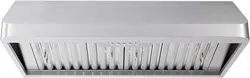
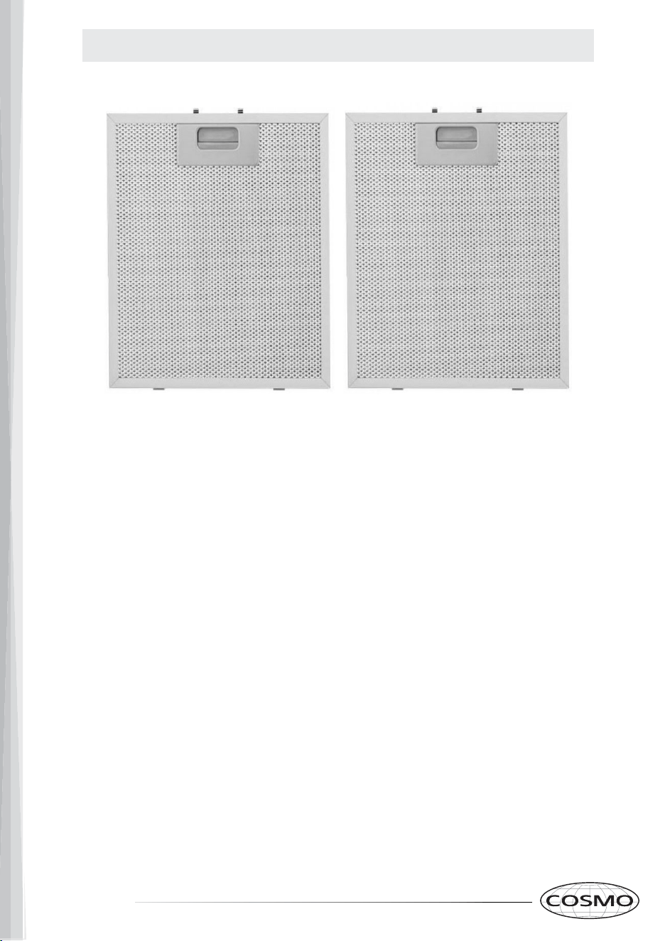
ALUMINUM FILTERS
About Your New Filters
Aluminum filters are recommended to be replaced every 4-6
months, depending on usage.
Cleaning my Aluminum Filters
Your filters can be hand washed and cleaned to increase time
between replacements. Aluminum filters should not be placed
in the dishwasher.
Additional Aluminum or Charcoal Filters can be purchased from:
www.cosmoappliances.com
4 5
Read all instructions before using this appliance.
Save these instructions for future reference.
Approved for residential appliances.
For residential use only.
FOR GENERAL VENTILATING USE ONLY. DO NOT USE
TO EXHAUST HAZARDOUS OR EXPLOSIVE MATERIALS
OR VAPORS.
CAUTION
CAUTION
WARNING
WARNING
WARNING
WARNING
WARNING
WARNING
WARNING
To reduce risk of fire and to properly exhaust
air, do not vent exhaust air into spaces within
walls, ceilings, attics, crawl spaces, or garages.
TO REDUCE THE RISK OF FIRE, USE ONLY METAL
DUCT WORK. Install this hood in accordance with all
requirements specified.
TO REDUCE THE RISK OF FIRE, ELECTRIC SHOCK,
OR INJURY TO PERSONS, OBSERVE THE FOLLOWING:
1. Use this unit only in the manner intended by the manu-
facturer. If you have questions, contact the manufacturer.
2. Before servicing or cleaning the unit, switch power off
at service panel and lock service panel disconnecting
means to prevent power from being switched on acci-
dentally. When the service disconnecting means cannot
be locked, securely fasten a prominent warning device,
such as a tag, to the service panel.
3. Installation work and electrical wiring must be done
by qualied person(s) in accordance with all applicable
codes and standards, including fire-rated construction.
4. Sufcient air is needed for proper combustion and
exhausting of gases through the flue (Chimney) of fuel
burning equipment to prevent back-drafting. Follow the
heating equipment manufacturer's guideline and safety
standards such as those published by the National Fire
Protection Association (NFPA), the American Society for
Heating, Refrigeration and Air Conditioning Engineers
(ASHRAE), and the local code authorities.
5. When cutting or drilling into wall or ceiling, do not
damage electrical wiring and other hidden utilities.
6. Ducted systems must always be vented to the outdoors.
To Reduce The Risk Of Fire Or Electric Shock, Do Not
Use This Hood With Any External Solid State Speed
Control Device.
Disconnect the appliance from the power source
before servicing.
GROUNDING INSTRUCTIONS
This appliance must be grounded. In the event of an electri-
cal short circuit, grounding reduces the risk of electric
shock by providing an escape wire for the electric current.
WARNING - IMPROPER GROUNDING CAN
RESULT IN A RISK OF ELECTRIC SHOCK.
Consult a qualified electrician if the grounding instructions
are not completely understood, or if doubt exists as to
whether the appliance is properly grounded.
TO REDUCE THE RISK OF INJURY TO PERSONS, IN THE
EVENT OF A RANGE TOP GREASE FIRE, OBSERVE THE
FOLLOWING:
• SMOTHER FLAMES with a close-fitting lid, cookie sheet,
or metal tray, then turn off the burner. BE CAREFUL TO
PREVENT BURNS. If the flames do not go out immediately,
EVACUATE AND CALL THE FIRE DEPARTMENT.
• NEVER PICK UP A FLAMING PAN – You may be burned.
• DO NOT USE WATER, including wet dishcloths or towels –
a violent steam explosion will result.
• Use an extinguisher ONLY if:
1. You know you have a Class ABC extinguisher, and you
already know how to operate it.
2. The fire is small and contained in the area where it started.
3. The fire department is being called.
4. You can fight the fire with your back to an exit
Always leave safety grills and lters in place. Without these
components, operating blowers could catch onto hair, ngers
and loose clothing.
The manufacturer declines all responsibility in the event
of failure to observe the instructions given here for
installation, maintenance and suitable use of the product.
The manufacturer further declines all responsibility for injury
due to negligence and the warranty of the unit automatically
expires due to improper maintenance.
WARNING – TO REDUCE THE RISK OF A RANGE TOP
GREASE FIRE:
A. Never leave surface units unattended at high settings.
Boilovers cause smoking and greasy spillovers that may
ignite. Heat oils slowly on low or medium settings.
B. Always turn hood ON when cooking at high heat or
when flaming food (i.e. Crepes Suzette, Cherries Jubilee,
Peppercorn Beef Flambe).
C. Clean ventilating fans frequently. Grease should not be
allowed to accumulate on fan or filter.
D. Use proper pan size. Always use cookware appropriate
for the size of the surface element.
IMPORTANT SAFETY INSTRUCTIONS
ALUMINUM FILTERS
About Your New Filters
Aluminum filters are recommended to be replaced every 4-6
months, depending on usage.
Cleaning my Aluminum Filters
Your filters can be hand washed and cleaned to increase time
between replacements. Aluminum filters should not be placed
in the dishwasher.
Additional Aluminum or Charcoal Filters can be purchased from:
www.cosmoappliances.com
6 7
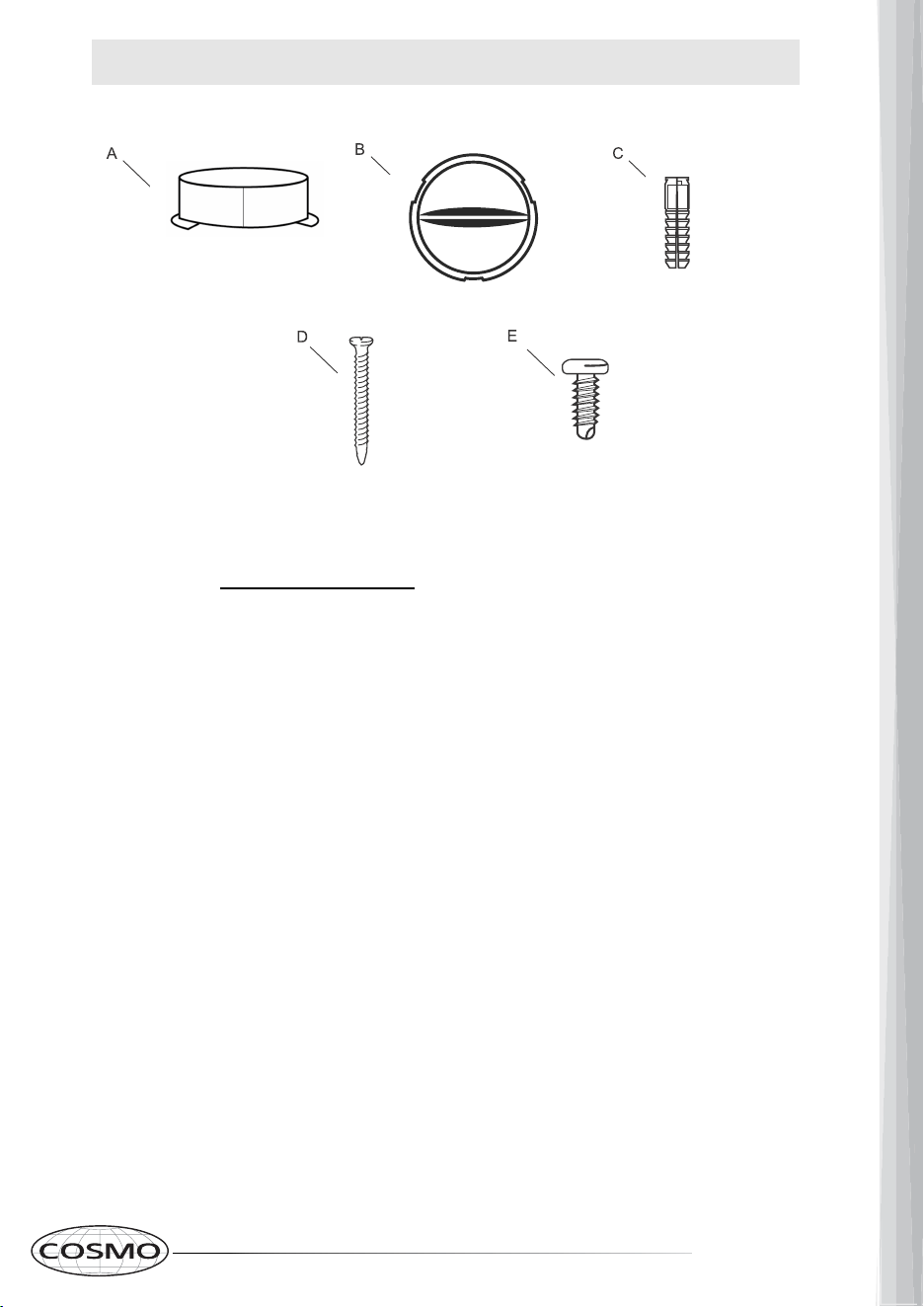
PARTS INCLUDED
A) Damper
B) Vent cover
C) Plastic Anchors - 2 pcs
D) ST4*40 mm wood screws - 9 pcs
E) ST4*16 mm wood screws - 2 pcs
PARTS LIST
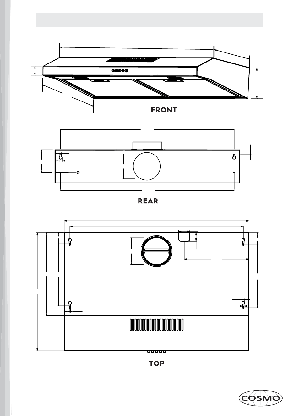
DIAGRAM: RANGE HOOD EXTERIOR
29.5"
1.6"
18.8"
13.2"
5.3"
27.7"
3.6"
0.23"
0.47"
0.18"
27.7"
0.8"
29.5"
27.7"
4.7"
1.4"
1.8"
2"
10.4"
10"
0.23"
0.18"
0.47"
18.8"
13.2"
10"
1.65"
4.7"
6 7
PARTS INCLUDED
A) Damper
B) Vent cover
C) Plastic Anchors - 2 pcs
D) ST4*40 mm wood screws - 9 pcs
E) ST4*16 mm wood screws - 2 pcs
PARTS LIST
DIAGRAM: RANGE HOOD EXTERIOR
29.5"
1.6"
18.8"
13.2"
5.3"
27.7"
3.6"
0.23"
0.47"
0.18"
27.7"
0.8"
29.5"
27.7"
4.7"
1.4"
1.8"
2"
10.4"
10"
0.23"
0.18"
0.47"
18.8"
13.2"
10"
1.65"
4.7"
8 9
INSTALLATION REQUIREMENTS
Min.
Max.
30"/ 36"
Fig. 1
30"
24"
WARNING
ALL ELECTRICAL CONNECTIONS MUST BE IN ACCORDANCE WITH LOCAL
CODES, ORDINANCES, OR NATIONAL ELECTRICAL CODE. IF YOU ARE
UNFAMILIAR WITH METHODS OF INSTALLING ELECTRICAL WIRING, SECURE
THE SERVICES OF A QUALIFIED ELECTRICIAN.
Sufcient air is needed for proper combustion and exhausting of gases through the
chimney of fuel burning equipment to prevent back-drafting.
Follow the cooking equipment manufacturer's guideline and safety standards such as
those published by the National Fire Protection Association (NFPA), the American Society
for Heating, Refrigeration and Air Conditioning Engineers (ASHRAE), and local code.
When cutting or drilling into wall or ceiling, do not damage electrical wiring and other
hidden utilities. Ducted systems must always be vented outdoors.
PLEASE READ THE FOLLOWING INSTRUCTIONS CAREFULLY:
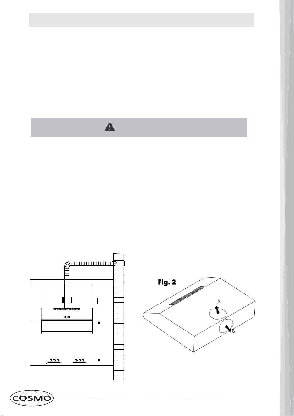
1. This Range Hood can be vented through the top or back.
For ductless installation, install an Air Outlet Cap on the rear vent hole. If air will be
vented, install the damper attachment on the side that the air will vent through (top or
rear, shown in Fig. 2)
2. For optimal performance the Range Hood must be installed 24” - 30” in height from the
cooktop. (Fig. 1)
3. Electrical Requirements: Rated Voltage and Frequency:) 110-120V~ 60Hz. Motor Input
Power: 90W
PRE-INSTALLATION
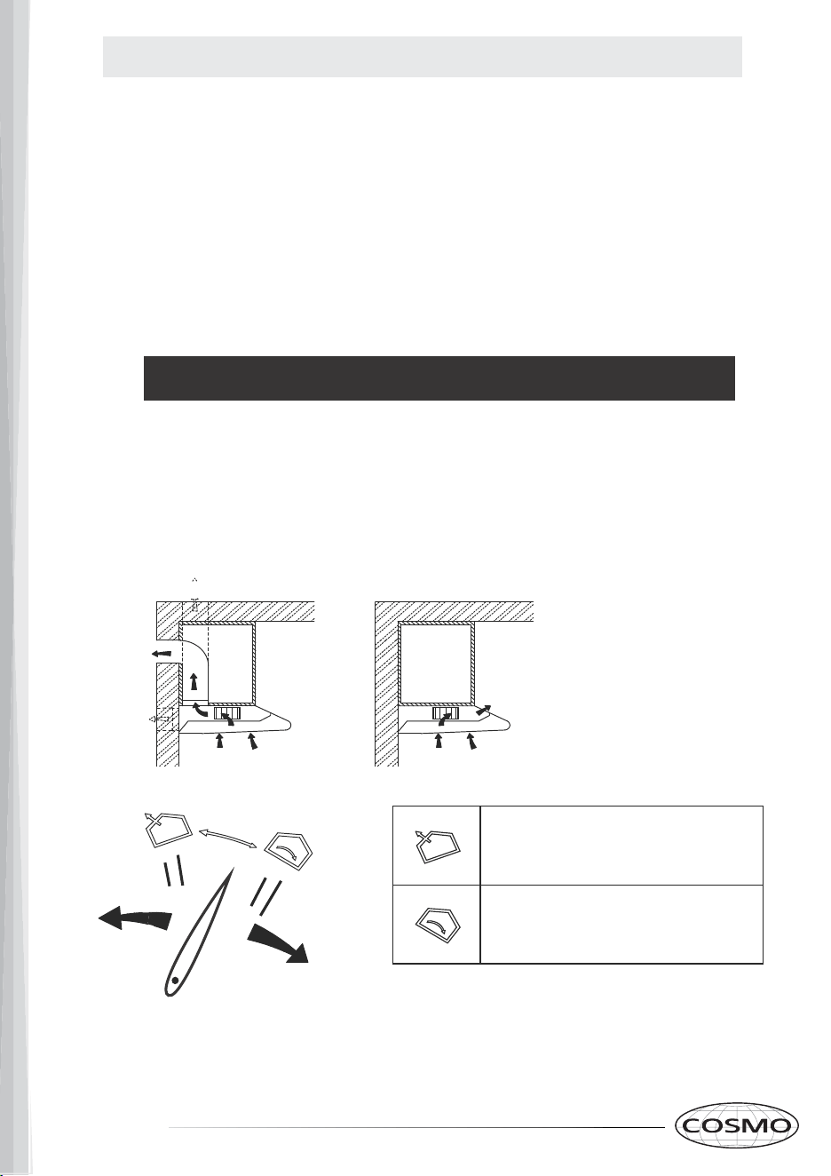
Ducted Mode Recircula�ng Mode
Ducted Mode: Turn the knob to this se�ng
for Ducted Installa�on.
Recircula�ng Mode: Turn the knob to this
se�ng for a Recirula�ng Installa�on.
•
Please read the instructions carefully. Unpack the Range Hood and check that all
functions are working before installing.
• Ensure that the voltage (V) and the frequency (Hz) indicated on the sticker match the
voltage and frequency at the installation site.
• Check that the area behind the installation surface to be drilled is clear of any electrical
cables or pipes, etc.
• The stainless steel surfaces of the Range Hood are very easily damaged during
installation if scratched or bumped by tools. Please take care to protect the surfaces
during installation.
• Protect the cooktop surface below with plywood, or similar material, to prevent
damage occurring during installation.
• The manufacturer shall not be held liable for failure to observe all safety regulations.
IMPORTANT! READ BEFORE INSTALLATION !
You will need to set the Range Hood mode to either Ducted or Recirculating.
1. Remove Aluminum Filters
2.
Locate Knob Settings located under the Motor (Fig. 3)
3.
Rotate the lever to either Ducted or Recirculating mode.
4.
If recirculating mode is chosen, install the vent cover on the rear vent hole.
If ducted mode is chosen, install the damper on the vent hole where the air will vent
through (top or rear), and install the vent cover on the other vent hole (shown on Fig.2
of the previous page).
Fig.3 Venting mode
8 9
INSTALLATION REQUIREMENTS
Min.
Max.
30"/ 36"
Fig. 1
30"
24"
WARNING
ALL ELECTRICAL CONNECTIONS MUST BE IN ACCORDANCE WITH LOCAL
CODES, ORDINANCES, OR NATIONAL ELECTRICAL CODE. IF YOU ARE
UNFAMILIAR WITH METHODS OF INSTALLING ELECTRICAL WIRING, SECURE
THE SERVICES OF A QUALIFIED ELECTRICIAN.
Sufcient air is needed for proper combustion and exhausting of gases through the
chimney of fuel burning equipment to prevent back-drafting.
Follow the cooking equipment manufacturer's guideline and safety standards such as
those published by the National Fire Protection Association (NFPA), the American Society
for Heating, Refrigeration and Air Conditioning Engineers (ASHRAE), and local code.
When cutting or drilling into wall or ceiling, do not damage electrical wiring and other
hidden utilities. Ducted systems must always be vented outdoors.
PLEASE READ THE FOLLOWING INSTRUCTIONS CAREFULLY:
1. This Range Hood can be vented through the top or back.
For ductless installation, install an Air Outlet Cap on the rear vent hole. If air will be
vented, install the damper attachment on the side that the air will vent through (top or
rear, shown in Fig. 2)
2. For optimal performance the Range Hood must be installed 24” - 30” in height from the
cooktop. (Fig. 1)
3. Electrical Requirements: Rated Voltage and Frequency:) 110-120V~ 60Hz. Motor Input
Power: 90W
PRE-INSTALLATION
Ducted Mode Recircula�ng Mode
Ducted Mode: Turn the knob to this se�ng
for Ducted Installa�on.
Recircula�ng Mode: Turn the knob to this
se�ng for a Recirula�ng Installa�on.
•
Please read the instructions carefully. Unpack the Range Hood and check that all
functions are working before installing.
• Ensure that the voltage (V) and the frequency (Hz) indicated on the sticker match the
voltage and frequency at the installation site.
• Check that the area behind the installation surface to be drilled is clear of any electrical
cables or pipes, etc.
• The stainless steel surfaces of the Range Hood are very easily damaged during
installation if scratched or bumped by tools. Please take care to protect the surfaces
during installation.
• Protect the cooktop surface below with plywood, or similar material, to prevent
damage occurring during installation.
• The manufacturer shall not be held liable for failure to observe all safety regulations.
IMPORTANT! READ BEFORE INSTALLATION !
You will need to set the Range Hood mode to either Ducted or Recirculating.
1. Remove Aluminum Filters
2.
Locate Knob Settings located under the Motor (Fig. 3)
3.
Rotate the lever to either Ducted or Recirculating mode.
4.
If recirculating mode is chosen, install the vent cover on the rear vent hole.
If ducted mode is chosen, install the damper on the vent hole where the air will vent
through (top or rear), and install the vent cover on the other vent hole (shown on Fig.2
of the previous page).
Fig.3 Venting mode
10 11
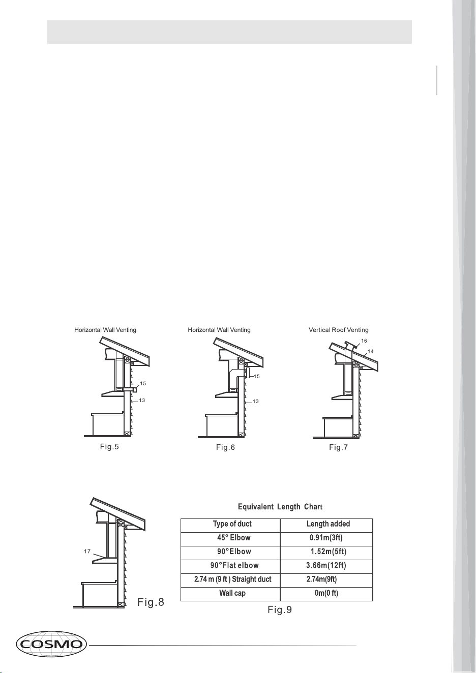
PRE-INSTALLATION
• Your venting system must vent to the outdoors either horizontally through the
back wall (13) or vertically through the roof (14). (refer to Fig. 5/Fig. 6/Fig. 7).
• For this range hood, use 5 in. round metal ductwork for the top -OR- use
rectangular adapter / ductwork for the back. Connect to damper using
HVAC aluminum tape.
• The total duct length should not be more than 35 ft. Calculate the total
effective length of the ductwork by using the table below. For each fit-
ting use the table to see its straight duct equivalent.
• Fasten all ductwork with sheet metal screws and tape all joints with
certified HVAC tape.
• If you must turn the path of the ductwork using elbows, keep the number of elbows to
a minimum for best performance. Use no more than three 90 degree elbows. En-
sure that there is a minimum of 25.6 in. of straight vent between each elbow. Use el-
bows as far away from the range hoods exhaust opening as possible.
• Cap the exterior of the duct with a wall cap (15) or roof cap (16). Never use (4 in.)
laundry-type wall caps. Use caulking to seal exterior wall or roof opening around
the cap.
• The venting system must have a damper. If the roof or wall cap has a damper, do
not use the damper supplied with the range hood.
If using recirculating mode, ignore this section.
For recirculating mode, air will vent out of the front vent
holes. (17 in Fig. 8)
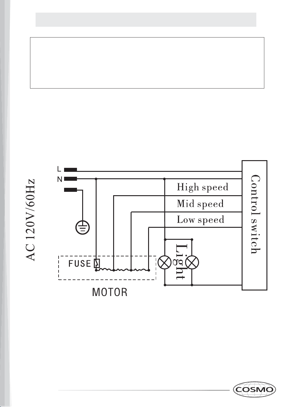
WIRING DIAGRAM
CAUTION: SHUT-OFF POWER SUPPLY BEFORE INSTALLING. IN-
STALLATION WORK AND ELECTRICAL WIRING MUST BE DONE BY
QUALIFIED PERSON(S) IN ACCORDANCE WITH ALL APPLICABLE
CODES & STANDARDS, INCLUDING FIRE-RATED CONSTRUCTION.
E
10 11
PRE-INSTALLATION
• Your venting system must vent to the outdoors either horizontally through the
back wall (13) or vertically through the roof (14). (refer to Fig. 5/Fig. 6/Fig. 7).
• For this range hood, use 5 in. round metal ductwork for the top -OR- use
rectangular adapter / ductwork for the back. Connect to damper using
HVAC aluminum tape.
• The total duct length should not be more than 35 ft. Calculate the total
effective length of the ductwork by using the table below. For each fit-
ting use the table to see its straight duct equivalent.
• Fasten all ductwork with sheet metal screws and tape all joints with
certified HVAC tape.
• If you must turn the path of the ductwork using elbows, keep the number of elbows to
a minimum for best performance. Use no more than three 90 degree elbows. En-
sure that there is a minimum of 25.6 in. of straight vent between each elbow. Use el-
bows as far away from the range hoods exhaust opening as possible.
• Cap the exterior of the duct with a wall cap (15) or roof cap (16). Never use (4 in.)
laundry-type wall caps. Use caulking to seal exterior wall or roof opening around
the cap.
• The venting system must have a damper. If the roof or wall cap has a damper, do
not use the damper supplied with the range hood.
If using recirculating mode, ignore this section.
For recirculating mode, air will vent out of the front vent
holes. (17 in Fig. 8)
WIRING DIAGRAM
CAUTION: SHUT-OFF POWER SUPPLY BEFORE INSTALLING. IN-
STALLATION WORK AND ELECTRICAL WIRING MUST BE DONE BY
QUALIFIED PERSON(S) IN ACCORDANCE WITH ALL APPLICABLE
CODES & STANDARDS, INCLUDING FIRE-RATED CONSTRUCTION.
E
12 13
INSTALLATION INSTRUCTIONS
CAUTION: HOOD MAY HAVE VERY SHARP EDGES; PLEASE WEAR
PROTECTIVE GLOVES WHENEVER IT IS NECESSARY TO REMOVE
ANY PARTS FOR INSTALLING, CLEANING OR SERVICING.
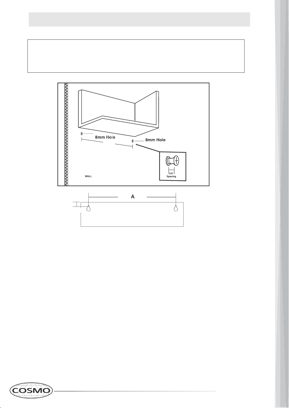
1. Drill two 8mm holes in position for plastic wall anchor (Part B) placement.
(See above for placement location).
2.
Tap plastic wall anchors securely into each of the drilled holes.
3.
After Wall anchors have been tapped in place, Insert ST4*40 wood screws (part D), but
leave 1/4” of the screw sticking out of the wall. (This will give your Range Hood
something to hang onto).
B
30” Model:
A= 25.6”
B = 1 - 1/8"
A
CABINET
If using recirculating mode: skip steps 4, 5a,
5c, 6a, 6c.
If cabinet bottom is recessed, we recommend installing wooden shims on cabinet bottom to make
cabinet mounting area flush.
INSTALLATION INSTRUCTIONS
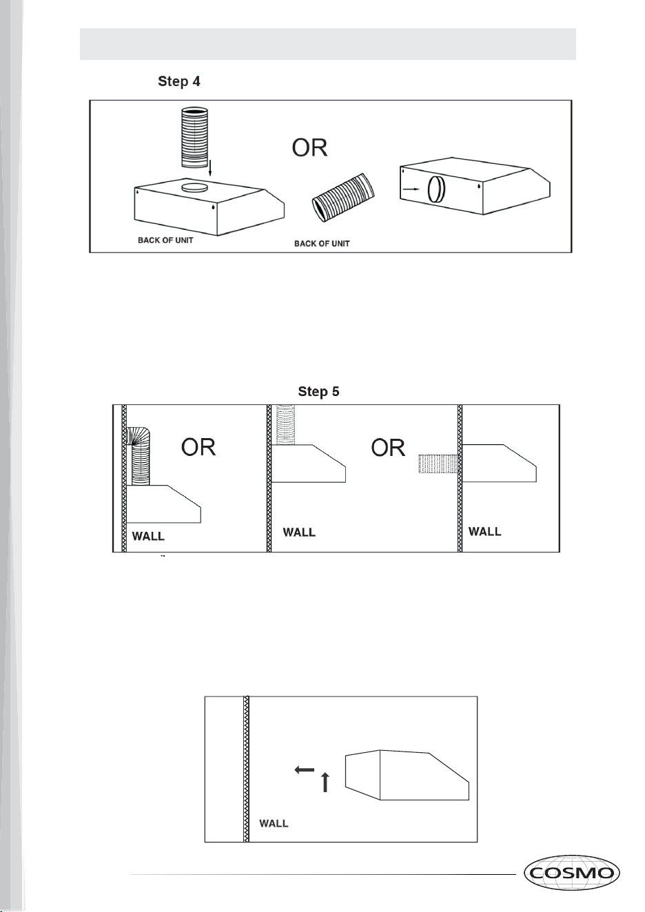
5. 5a. If mounting to the wall only, drill a 5.25” round hole on the back wall above the hood, OR
into the ceiling directly above the hood, or on the back wall centered with the rear vent hole of the
hood. (Skip this step for recirculating mode)
5b. Lift the hood and hang the hood unit on the back wall using the screws drilled in Step 3.
Once the hood is securely hung on the wall, tighten the screws from the interior of the hood
after removing the aluminum filters.
5c. Pull rectangular adapter / ductwork through the newly drilled hole in the wall. Connect unit to
power source. (Skip this step for recirculating mode)
Step 5b.
If mounting to a cabinet, skip step 5.
4. Take the hood unit along with the 5” Round Aluminum duct (Top) -OR-
rectangular adapter / ductwork (Back). Secure the round aluminum duct to
the damper at the top or rear of the hood unit using HVAC Aluminum foil
tape. (Skip this step for recirculating mode)
12 13
INSTALLATION INSTRUCTIONS
CAUTION: HOOD MAY HAVE VERY SHARP EDGES; PLEASE WEAR
PROTECTIVE GLOVES WHENEVER IT IS NECESSARY TO REMOVE
ANY PARTS FOR INSTALLING, CLEANING OR SERVICING.
1. Drill two 8mm holes in position for plastic wall anchor (Part B) placement.
(See above for placement location).
2.
Tap plastic wall anchors securely into each of the drilled holes.
3.
After Wall anchors have been tapped in place, Insert ST4*40 wood screws (part D), but
leave 1/4” of the screw sticking out of the wall. (This will give your Range Hood
something to hang onto).
B
30” Model:
A= 25.6”
B = 1 - 1/8"
A
CABINET
If using recirculating mode: skip steps 4, 5a,
5c, 6a, 6c.
If cabinet bottom is recessed, we recommend installing wooden shims on cabinet bottom to make
cabinet mounting area flush.
INSTALLATION INSTRUCTIONS
5. 5a. If mounting to the wall only, drill a 5.25” round hole on the back wall above the hood, OR
into the ceiling directly above the hood, or on the back wall centered with the rear vent hole of the
hood. (Skip this step for recirculating mode)
5b. Lift the hood and hang the hood unit on the back wall using the screws drilled in Step 3.
Once the hood is securely hung on the wall, tighten the screws from the interior of the hood
after removing the aluminum filters.
5c. Pull rectangular adapter / ductwork through the newly drilled hole in the wall. Connect unit to
power source. (Skip this step for recirculating mode)
Step 5b.
If mounting to a cabinet, skip step 5.
4. Take the hood unit along with the 5” Round Aluminum duct (Top) -OR-
rectangular adapter / ductwork (Back). Secure the round aluminum duct to
the damper at the top or rear of the hood unit using HVAC Aluminum foil
tape. (Skip this step for recirculating mode)
14 15
INSTALLATION INSTRUCTIONS
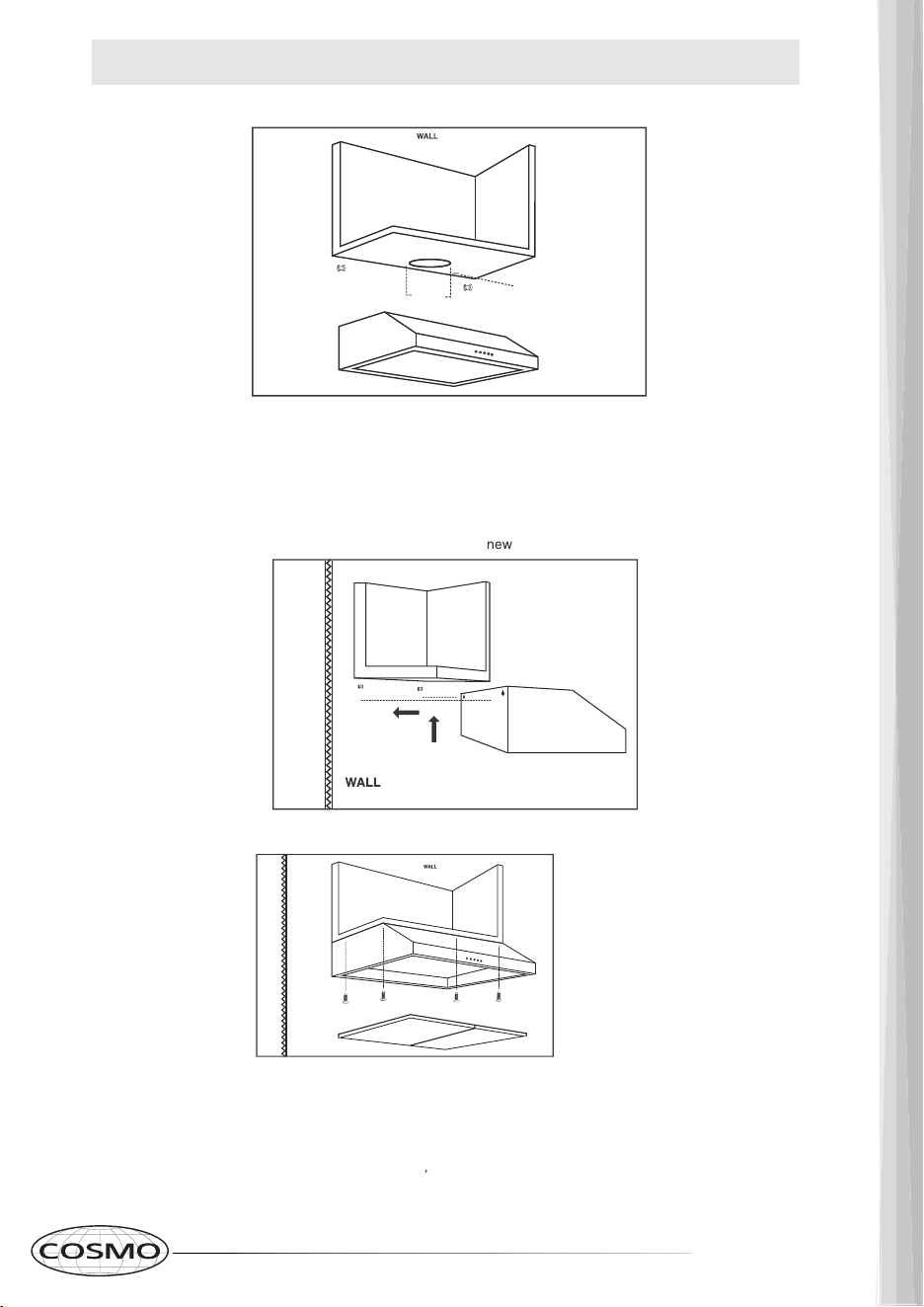
6.
6a. Drill a 5 - 1/4” Round Hole into the bottom of the cabinet. (skip this step for
recirculating mode)
6b. Drill a 1 - 1/2” hole into the bottom of the cabinet for the Electrical Access hole
according to the location of electrical wires shown on page 5 of this manual.
6c. Pull the round duct through the bottom of the new cabinet holes (skip this step for
recirculating mode).
7. Lift the hood and hang the hood unit on the back wall using the screws drilled in Step 3.
8.
Once the hood is securely hung to the back wall, remove the aluminum filters from underneath the
hood.
9. Drill four pieces of ST4*16 wood screws (Part E) into the bottom of the cabinet using the
four screw holes at the top of the hood.
Once the hood is secured into the cabinet tighten the wood screws located in the back
of the hood. Re-install the filters. Reconnect unit to power source.
Step 7
Step 8-9
Step 6
ELECTRICAL
ACCESS HOLE
5.25"
6d. Pull the electrical cord through the bottom of the
cabinet holes.
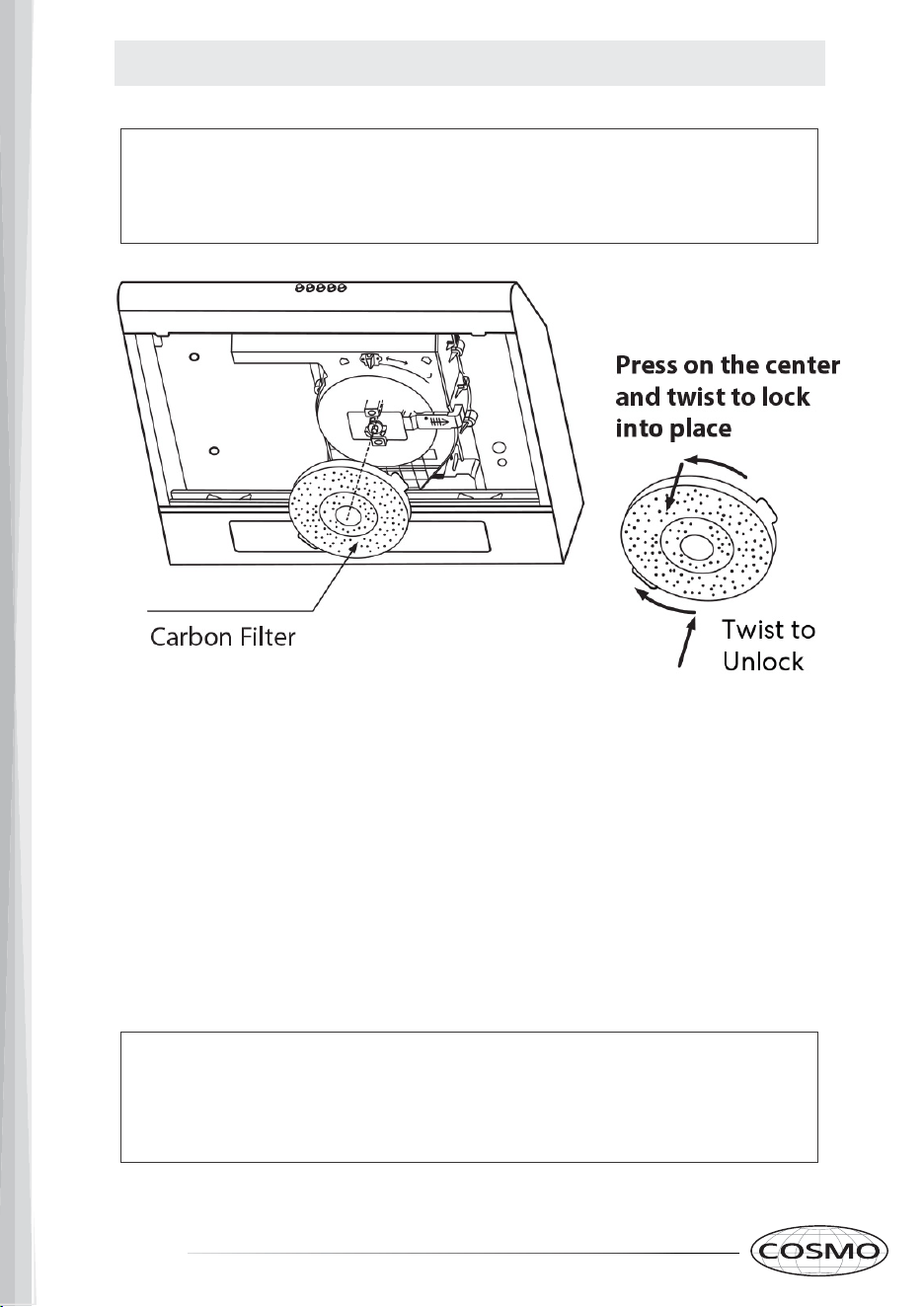
RECIRCULATING CARBON FILTERS
SKIP THIS PAGE IF YOU ARE INSTALLING A DUCTED RANGE
HOOD. CARBON FILTERS ARE ONLY INCLUDED WITH
DUCTLESS MODELS.
Installing Recirculating Filters (For Ductless installation Only)
1. Remove the Aluminum Filters.
2. The charcoal filter is installed to the motor housing as
shown. Line up the filter over the center of the motor
housing, then turn the filter until the side tabs fit into
slots and locks in place.
3. To replace the carbon filter reverse the process and repeat.
THE CARBON FILTER MUST BE REPLACED EVERY 4-6 MONTHS
DEPENDING ON USE. ADDITIONAL ALUMINUM OR CHARCOAL
FILTERS CAN BE PURCHASED FROM: WWW.COSMOAPPLIANCES.COM
Charcoal Filter Part # - CFK3-TM
14 15
INSTALLATION INSTRUCTIONS
6.
6a. Drill a 5 - 1/4” Round Hole into the bottom of the cabinet. (skip this step for
recirculating mode)
6b. Drill a 1 - 1/2” hole into the bottom of the cabinet for the Electrical Access hole
according to the location of electrical wires shown on page 5 of this manual.
6c. Pull the round duct through the bottom of the new cabinet holes (skip this step for
recirculating mode).
7. Lift the hood and hang the hood unit on the back wall using the screws drilled in Step 3.
8.
Once the hood is securely hung to the back wall, remove the aluminum filters from underneath the
hood.
9. Drill four pieces of ST4*16 wood screws (Part E) into the bottom of the cabinet using the
four screw holes at the top of the hood.
Once the hood is secured into the cabinet tighten the wood screws located in the back
of the hood. Re-install the filters. Reconnect unit to power source.
Step 7
Step 8-9
Step 6
ELECTRICAL
ACCESS HOLE
5.25"
6d. Pull the electrical cord through the bottom of the
cabinet holes.
RECIRCULATING CARBON FILTERS
SKIP THIS PAGE IF YOU ARE INSTALLING A DUCTED RANGE
HOOD. CARBON FILTERS ARE ONLY INCLUDED WITH
DUCTLESS MODELS.
Installing Recirculating Filters (For Ductless installation Only)
1. Remove the Aluminum Filters.
2. The charcoal filter is installed to the motor housing as
shown. Line up the filter over the center of the motor
housing, then turn the filter until the side tabs fit into
slots and locks in place.
3. To replace the carbon filter reverse the process and repeat.
THE CARBON FILTER MUST BE REPLACED EVERY 4-6 MONTHS
DEPENDING ON USE. ADDITIONAL ALUMINUM OR CHARCOAL
FILTERS CAN BE PURCHASED FROM: WWW.COSMOAPPLIANCES.COM
Charcoal Filter Part # - CFK3-TM
16 17
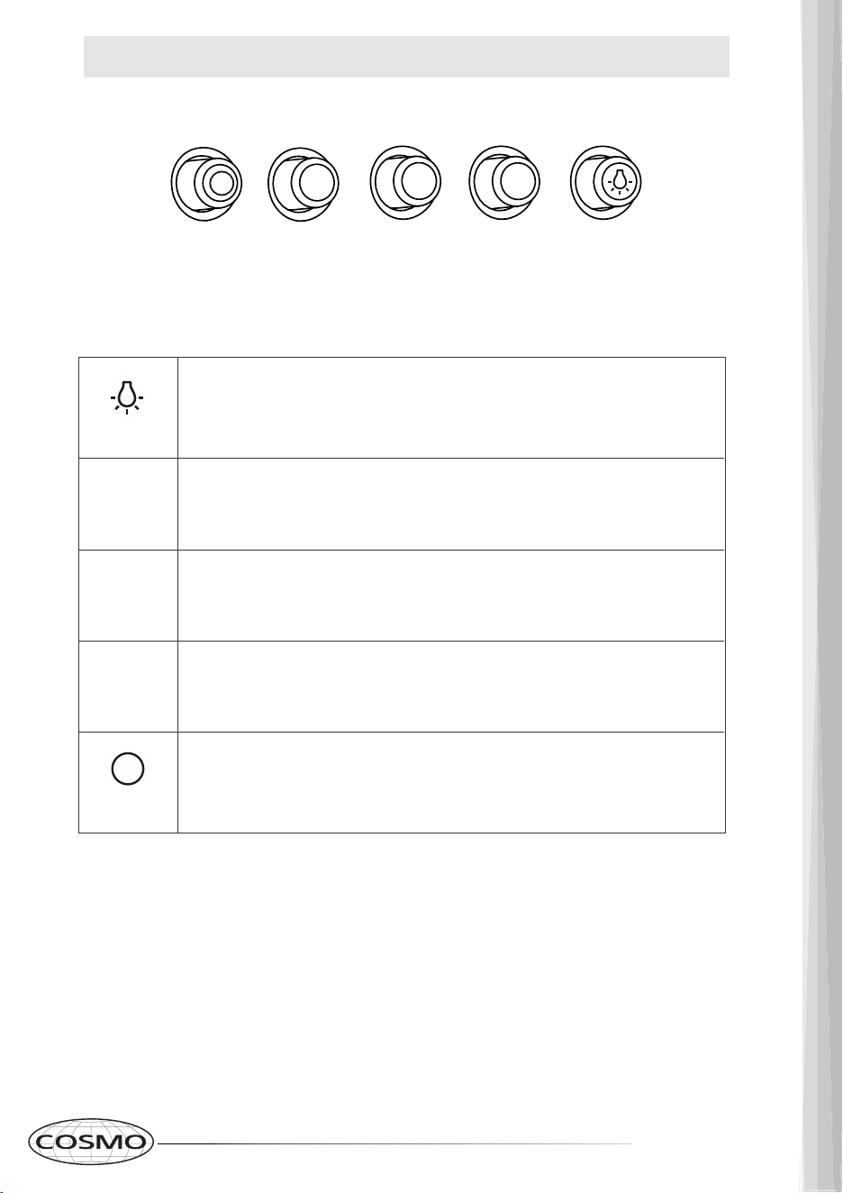
OPERATING INSTRUCTIONS
Low
Speed
Medium
Speed
High
Speed
Motor Off
Switch
Press this button to turn on the lights, and press
again to turn them off.
Press this button to run the motor at low speed.
Press this button to run the motor at medium speed.
Press this button to run the motor at high speed.
Press this button to stop the motor while it is running
on any given speed.
Light
Low
Speed
Medium
Speed
High
Speed
Motor Off
Switch
1
2
1
2
3
3
Light
MAINTENANCE
CAUTION: NEVER PUT YOUR HAND INSIDE OF THE UNIT WHILE
IT IS OPERATING. FOR THE BEST PERFORMANCE CLEAN YOUR
RANGE HOOD REGULARLY.
CLEANING
1. Use only mild soap or cleaning solutions to clean the hood’s outer surface.
Dry surfaces using a soft cloth.
2. Stainless Steel cleaner may be used on the external surface.
3.
Clean the Range Hood motor assembly every 1 to 3 months depending on use.
4. DO NOT clean the motor or electrical components with water or any
other liquid.
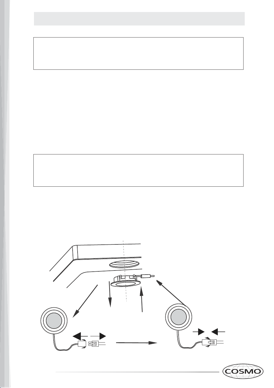
REPLACING LIGHT BULBS
CAUTION: LAMP UNIT MAY BE HOT! WAIT UNTIL THE UNIT IS COOL.
BEFORE ATTEMPTING TO REPLACE THE LED LAMPS. MAKE SURE
THE UNIT IS POWERED OFF AND DISCONNECTED.
1. Remove the aluminum filters
2. Disconnect the wire for the LED light being replaced.
3. Reach your hand into the unit and push the LED light housing out of
the hole to remove it. Replace the LED light and connect the wire.
4. Reinstall the aluminum filters
16 17
OPERATING INSTRUCTIONS
Low
Speed
Medium
Speed
High
Speed
Motor Off
Switch
Press this button to turn on the lights, and press
again to turn them off.
Press this button to run the motor at low speed.
Press this button to run the motor at medium speed.
Press this button to run the motor at high speed.
Press this button to stop the motor while it is running
on any given speed.
Light
Low
Speed
Medium
Speed
High
Speed
Motor Off
Switch
1
2
1
2
3
3
Light
MAINTENANCE
CAUTION: NEVER PUT YOUR HAND INSIDE OF THE UNIT WHILE
IT IS OPERATING. FOR THE BEST PERFORMANCE CLEAN YOUR
RANGE HOOD REGULARLY.
CLEANING
1. Use only mild soap or cleaning solutions to clean the hood’s outer surface.
Dry surfaces using a soft cloth.
2. Stainless Steel cleaner may be used on the external surface.
3.
Clean the Range Hood motor assembly every 1 to 3 months depending on use.
4. DO NOT clean the motor or electrical components with water or any
other liquid.
REPLACING LIGHT BULBS
CAUTION: LAMP UNIT MAY BE HOT! WAIT UNTIL THE UNIT IS COOL.
BEFORE ATTEMPTING TO REPLACE THE LED LAMPS. MAKE SURE
THE UNIT IS POWERED OFF AND DISCONNECTED.
1. Remove the aluminum filters
2. Disconnect the wire for the LED light being replaced.
3. Reach your hand into the unit and push the LED light housing out of
the hole to remove it. Replace the LED light and connect the wire.
4. Reinstall the aluminum filters
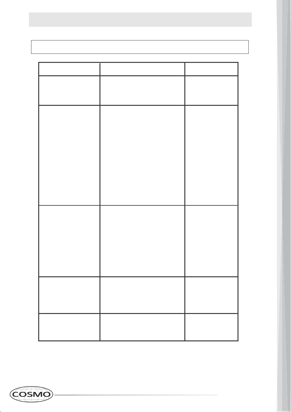
18 19
TROUBLESHOOTING
PROBLEM SOLUTION TOOLS
My range hood is noisy. Phillips Screwdriver
Gloves
Phillips Screwdriver
Gloves
Phillips Screwdriver
Gloves
Phillips Screwdriver
Nose Pliers
Gloves
Gloves
My range hood has
poor performance.
My range hood shakes.
The motor no longer
runs.
Light bulb went out.
A. Check inside the range hood
for any loose debris and remove.
A. The range hood and cooktop
are too far away from each
other. Optimal distance is 24”
to 30”.
B. There are too many open
windows or doors in the area.
Close some doors or windows.
C. The motor performance has
decreased due to wear. Replace
motor.
D. Check and make sure the
tape holding down the damper
flaps at the vent hole are
removed before use.
A. The installation is not secure.
Check again and make sure the
installation hardware is securely
mounted.
B. The fan is broken or not bal-
anced. Realign or replace fan.
C. The motor is loose. Check
and make sure the motor is
solidly mounted to the unit.
A. Replace control panel or
circuit board.
B. Replace with new motor
assembly.
A. Replace with a new LED light
2 watt max.
CAUTION: ALWAYS DISCONNECT UNIT FROM POWER BEFORE SERVICING

20 21
WARRANTY AND SERVICE
For full warranty details on this product please visit:
http://www.cosmoappliances.com/warranty
TO RECEIVE WARRANTY SERVICE, YOUR
PRODUCT MUST BE REGISTERED. TO REGISTER, VISIT:
WWW.COSMOAPPLIANCES.COM/WARRANTY
Correct Disposal of this product:
This marking indicates that this appliance should not
be disposed with other household wastes. To prevent
possible harm to the environment or human health
from uncontrolled waste disposal, recycle it responsibly to
promote the sustainable reuse of material resources.
IMPORTANT
Do Not Return This Product To The Store If
you have a problem with this product, please contact
Cosmo Customer Support at
+1(888)784-3108
DATED PROOF OF PURCHASE, MODEL #, AND SERIAL #
REQUIRED FOR WARRANTY SERVICE
IMPORTANT
Ne pas Réexpédier ce Produit au Magasin
Pour tout problème concernant ce produit, veuillez contacter
le service des consommateurs Cosmo Customer Support au
+1(888) 784-3108
UNE PREUVE D’ACHAT DATEE EST REQUISE POUR BENEFICIER DE
LA GARANTIE.
IMPORTANTE
No regrese este producto a la tienda
Si tiene algún problema con este producto, por favor contacte el
AYUDA AL CLIENTE COSMO al
+1(888)784-3108
(Válido solo en E.U.A).
NECESITA UNA PRUEBA DE DE COMPRA FECHADA, NÚMERO DE
MODELO Y DE SERIE PARA EL SERVICIO DE LA GARANTÍA
SCAN TO REGISTER
Electronic version of this manual is available at:
www.cosmoappliances.com
Cosmo is constantly making efforts to improve the quality and
performance of our products, so we may make changes to our
appliances without updating this manual.