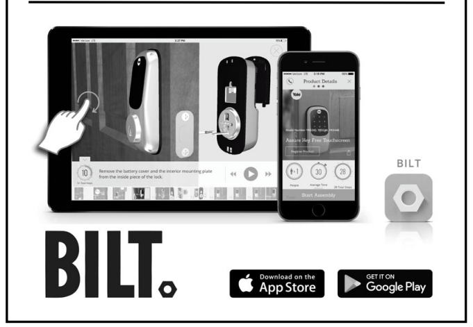
for step-by-step installation instructions & to register your product
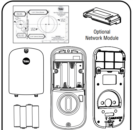
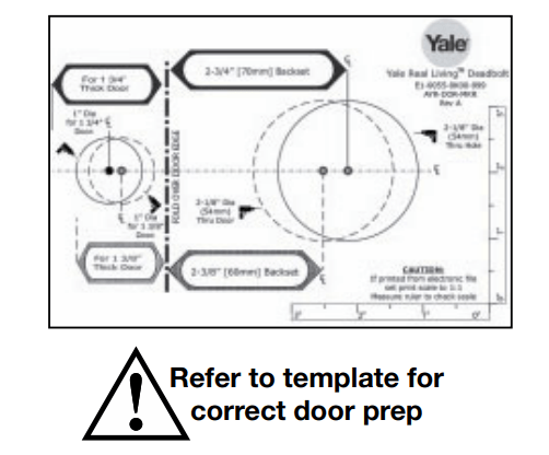
Preparing Door
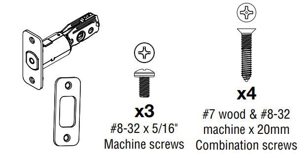
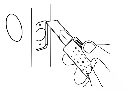
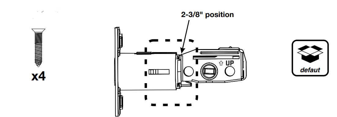
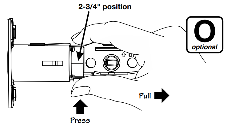
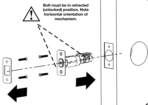
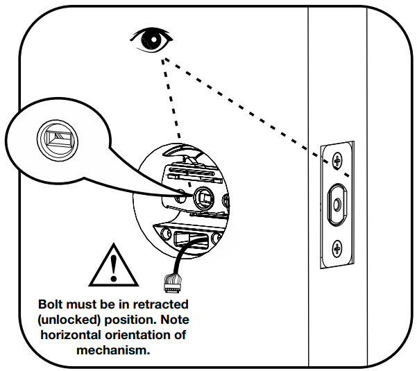
1. Installing Latch & Strike Plate
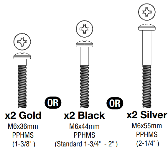
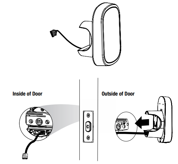
2. Installing Touchscreen Escutcheon
3. Installing Interior Mounting Plate
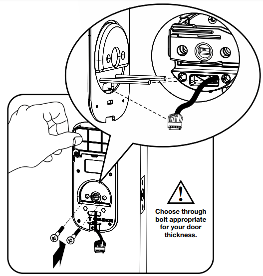
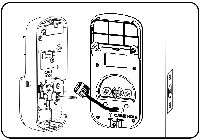
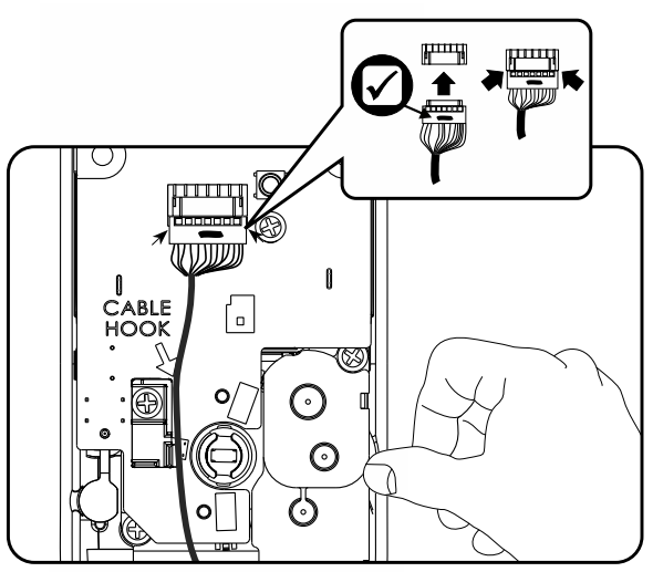
4. Attaching the Cable Assembly
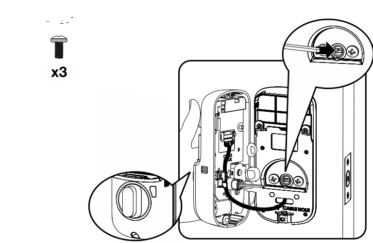
5. Installing Interior Escutcheon
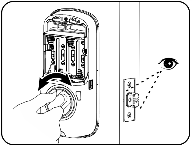
Testing Operation
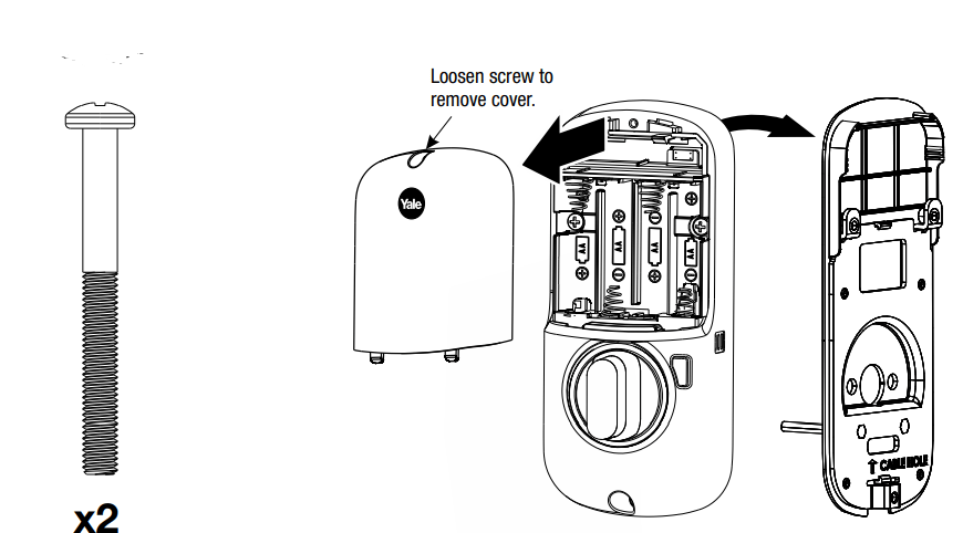
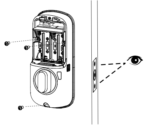
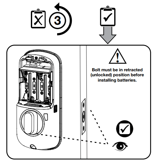
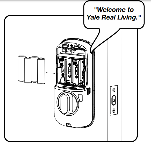
Installing Batteries/Handing the Lock
Lock automatically adjusts for proper handing.
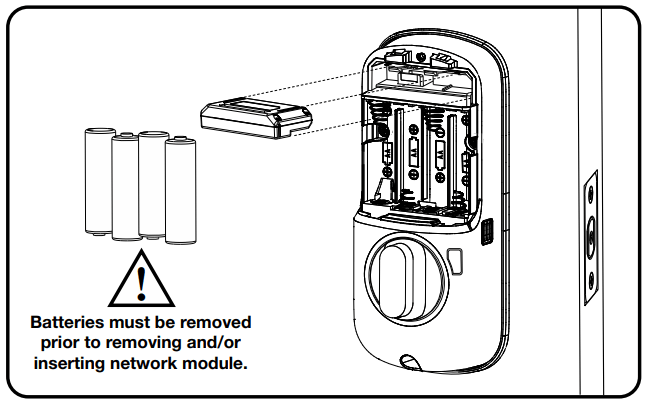
Installing Optional Network Module
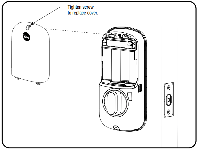
Installing Cover
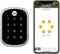
Congratulations, you've installed the Yale Assure Lock ® ® SL Key Free Touchscreen Deadbolt Continue to Programming Instructions to customize your product.
Programming Instructions
Exterior Escutcheon
Interior Escutcheon
Lock Activation
Master PIN Code must be created before any further programming.
Max User Codes = 250 with Z-Wave Plus or ZigBee network module
Max User Codes = 25 without network module or with iM1 network module
Max User Codes - 12 with Bluetooth
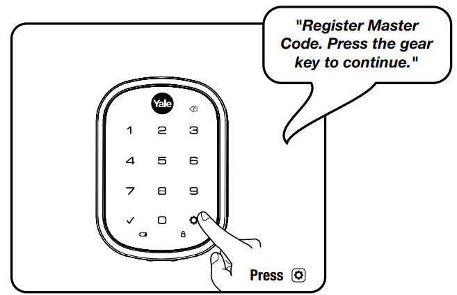
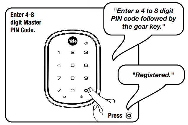
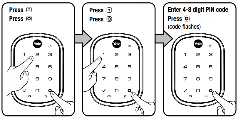
1. Creating Master Code
Creating a Master Code must be performed upon installation or after PIN resetting the lock to factory default. Programming and use of lock is not possible until this step has been successfully completed.
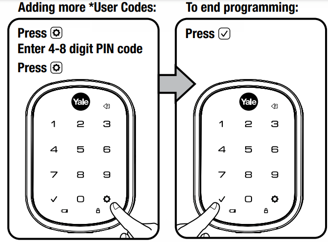
2. Creating User Codes
Master PIN code must be created first.
*Max user codes = 250 with Z-Wave Plus or ZigBee network module
Max user codes = 25 without network module or with iM1 network module
Max user codes = 12 with Bluetooth
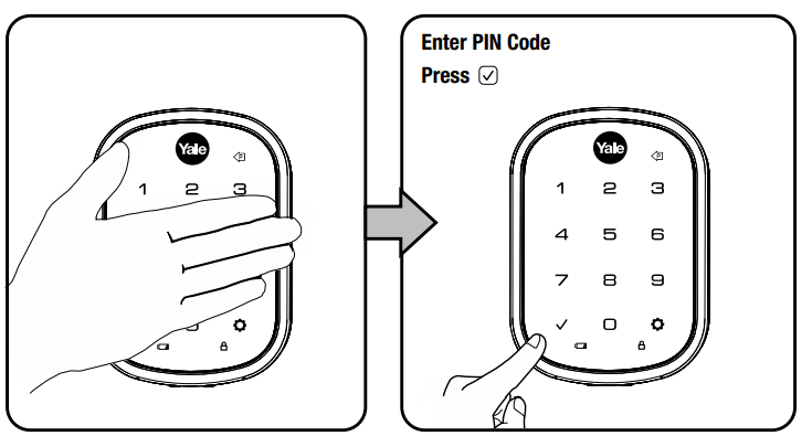
3. Unlocking Door with Code
Code Chart
Duplicate if necessary
PIN Code Management (With Network Module - Up to 250 Users)
User Name
PIN Code
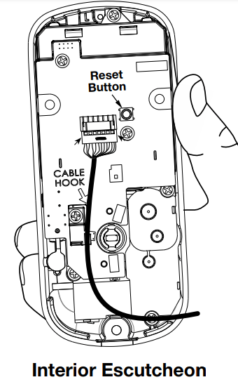
Resetting Lock to Factory Default
When lock is reset to factory defaults all user codes (including the Master PIN code*) are deleted and all programming features are reset to original default settings (see below).
1. Remove the battery cover and batteries.
2. Remove the interior escutcheon to access the reset button.
3. The reset button (see image at right) is located beside the PCB cable connector.
4. While pressing the reset button (minimum of 3 seconds) reinstall batteries. Release reset button.
5. Replace battery cover.
Upon reset, Master PIN Code creation is the only option available and must be performed prior to any other programming of the lock.
Factory Settings
Settings
Factory Setting
Master Code
Registration required*
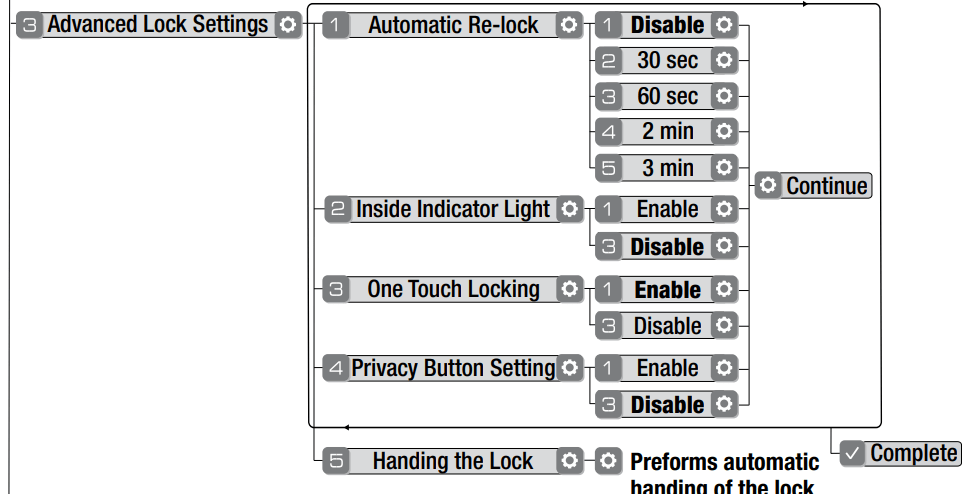
Automatic Re-lock
Disabled
Inside Indicator Light
Disabled (Off)
One Touch Locking
Enabled
Privacy Button Setting
Disabled
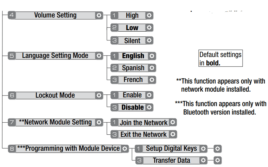
Volume Setting
Enabled (Low)
Language Setting
English
Lockout Mode
Disabled
Automatic Re-lock Time
30 Seconds
Wrong Code Entry Limit
5 Times
Shutdown Time
60 Seconds
*The Master PIN code must be registered prior to any other programming of the lock.
Definitions
All Code Lockout Mode: This feature is enabled by the Master code. When enabled, it restricts all user (except Master) PIN code access. When attempting to enter a code while the unit is in Lockout, the locked padlock will appear on the RED screen.
Automatic Re-lock Time: After a successful code entry or manual unlock with the key, the lock will automatically re-lock after each unlock in an effort to keep your home secure. This feature is optional, and can be turned off. In the ON mode, the lock will automatically re-lock after thirty (30) seconds.
Inside Indicator Light: Located on the interior escutcheon. Shows active status (Locked) of lock and can be enabled or disabled in the (Main Menu selection #3)
Language Setting Mode: Choosing English (1), Spanish (2) or French (3) becomes the (default) setting for the lock's voice prompts.
Low Battery: When battery power is low, the Low Battery Warning indicator flashes . If battery power is completely RED lost, use the 9Volt battery override. To use the 9V battery override apply 9V battery, in either direction, to terminals below the touchscreen for backup power option. Wake up the lock and enter your pin code to unlock the door.
Master Code: It must be created prior to PIN The Master code is used for programming and for feature settings. PIN programming the lock. The Master code will also operate (unlock/lock) the lock.
Network Module Setting: With the optional Network Module installed, this setting becomes available thru the Main Menu (7) and allows the lock to connect with a network controller.
One Touch Locking: When the latch is retracted, activating the keypad will extend the latch (during Automatic Re-lock duration or when Automatic Re-lock is disabled). When One-Touch Re-lock is in use any valid code will not (disabled), PIN re-lock the lock.
Previous: While in Menu Mode, pressing this icon cancels the current operation and returns the user to the previous step.
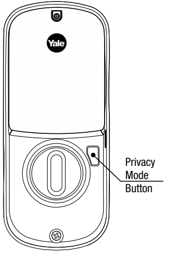
Privacy Mode: Privacy mode is disabled by default. Enable Privacy mode by pressing the privacy button for 4 seconds to put the lock in do-not-disturb mode (all pin codes are disabled).
Shutdown Time: The unit will shutdown (flashing ) for sixty (60) seconds and not allow operation after the wrong code RED entry limit (5 attempts) has been met. Tamper Alert: Audible alarm sounds if attempting to forcibly remove outside lock from door.
User Code: PIN The user code operates the lock. The maximum number of user codes with Z-Wave Plus or ZigBee network module is 250; without network module or with iM1 network module, maximum is 25; with Bluetooth, maximum is 12. Note: When deleting user pin code(s), screen will display user pin code being deleted.
Volume Setting Mode: Low (2) The volume setting for code verification is set to by default; otherwise it can be set to PIN High (1) Silent (3) or for quiet areas.
Wrong Code Entry Limit: After five (5) unsuccessful attempts at entering a valid code, the unit will shut down and not PIN allow operation for sixty (60) seconds.
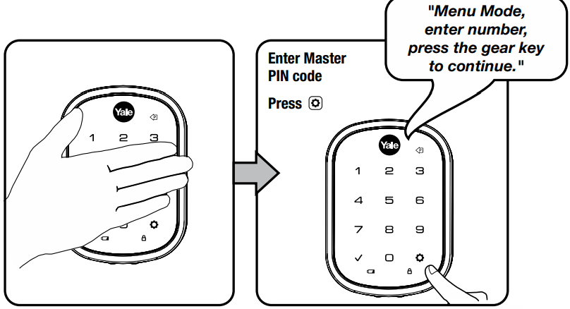
Feature Programming Through Menu Mode Using Master code*
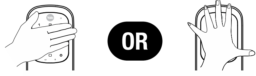
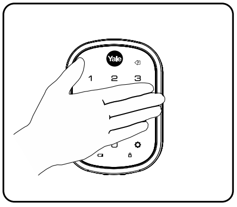
1. Touch screen with back of hand or palm to activate.
2. Enter 4-8 digit master code* followed by key. PIN Lock Response: "Menu mode, enter number, press key to continue."
3. Enter digit corresponding to the function to be performed followed by the key. Follow the voice commands.
*The Master code must be registered prior to any other programming PIN of the lock.
Programming Troubleshooting
Symptom
Suggested Action
Lock does not respond – door is open and accessible.
Touchscreen becomes active when pressed w/whole hand. Use a larger area of the hand or fingers and verify contact with at least 3 areas.
If touchscreen numbers are visible, check to see if they respond when pressed.
Check batteries are installed and oriented correctly (polarity) in the battery case.
Check batteries are in good condition; replace batteries* if discharged.
Check to see if touchscreen harness is fully connected and not pinched.
Lock does not respond – door is locked and inaccessible.
Batteries may be completely discharged.
Apply 9V battery to terminals below the touchscreen for backup power option.
Unit is on for a while then shows no reaction. Lights dim.
Batteries do not have enough power. Replace batteries*.
Unit chimes to indicate code acceptance, but the door will not open.
Check the door gaps for any foreign objects between door and frame.
Check that the wire harness is firmly connected to the PCB.
Unit operates to allow access, but will not automatically re-lock.
Check to see if Auto Re-lock Mode is enabled.
Disable Auto Re-lock Mode to lock the door (automatically).
If low battery indicator is lit (see below), change batteries *.
PIN codes will not register.
PIN codes must consist of 4 to 8 digits to register.
The same PIN code cannot be used for multiple users.
Registration/management of PIN codes is set by the authority of the Master Code, which is set first.
Contact the Master user.
User codes must be entered within 5 seconds (while touchscreen is active) or process will have to be restarted.
Check or gear cannot be used as part of the code.
Upon entering a code PIN and pressing key, the unit displays " invalid code" error or lock times out without responding.
Lockout Mode is enabled.
Only the Master can enable/disable Lockout Mode.
Contact the Master user.
Upon entering a code PIN and pressing the key, the red padlock icon appears and there are different tones.
Check to see if the lock is set to Lockout Mode.
Setting/managing Lockout Mode is done through Master Code only. Contact the Master user.
The unit operates, but it makes no sound.
Check to see if Silent Mode is enabled (see Feature #4).
The unit responds “low battery”
This is the alert to replace the batteries. Replace all four (4) batteries* with new Alkaline batteries.
Upon entering a code PIN and pressing the key, the unit responds " Wrong number of digits" .
The digits entered were incorrect or incomplete. Re-enter the correct code followed by the check key
* When batteries are replaced, Network Module locks have a real time clock that will be set through the User Interface (UI ); it is recommended to verify correct date and time particularly those locks operating under Daylight Saving Time ( DST ).
** Network Module locks only
Hardware Troubleshooting
Cycle lock in both the locked and unlocked positions. If problems are found:
Door is binding
a. Check that door and frame are properly aligned and door is free swinging.
b. Check hinges: They should not be loose or have excessive wear on knuckles.
Bolt will not deadlock
a. Check for sufficient clearance of the bolt within the strike-side jamb. Correct this by increasing the depth of the pocket for the bolt.
b. Check for misalignment of bolt and/or strike which may be preventing bolt from properly entering the strike. With the door open, extend and retract the bolt; if it is smooth, check the strike alignment.
Bolt does not extend or retract smoothly
a. Bolt and strike are misaligned, see above.
b. Check the backset of door relative to adjustments already made to bolt.
c. Verify proper door preparation and re-bore holes that are too small or misaligned.
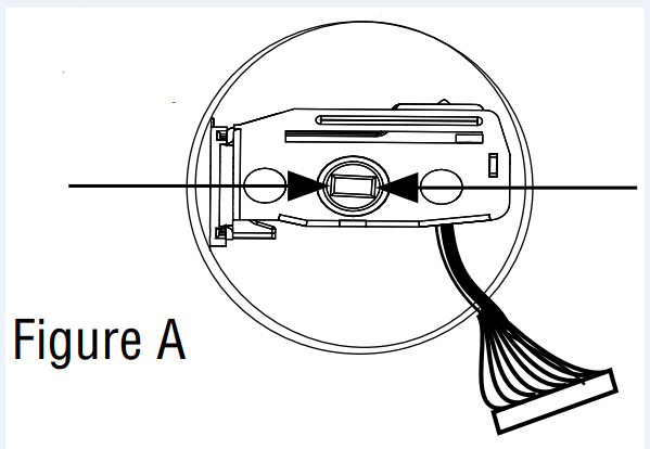
d. Verify keypad wire harness is routed under the bolt (see Fig. A).
e. Verify bolt is installed with correct side up (Fig. A).
Keypad numerics are scrolling
Remove interior escutcheon and check to ensure that the wire harness lies flat against the back recessed area and is properly routed along the side of the escutcheon and tucked under the plastic cable guide.

 Continue to Programming Instructions to customize your product.
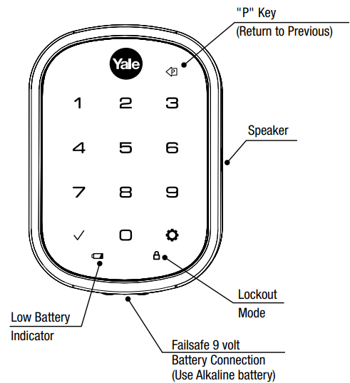

 key. PIN Lock Response: "Menu mode, enter number, press
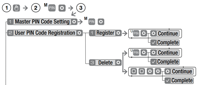
 or
or gear cannot be used as part of the code.