Loading ...
Loading ...
Loading ...
INSTALLATION INSTRUCTIONS
16
INSTALL THE RANGE
4. Electric ignition
There are separate ignition devices for the left and
right hand surface burners. Both of these ignition
devices are ON when any knob is turned to the LITE
setting. The ignition devices will spark as long as
any of the top burner knobs are at the LITE setting.
In the event of an electrical power failure, the top
knobs can still be used. To light a burner, hold a lit
kitchen match adjacent to the top burner to be used
and turn the valve knob to LITE.
USE EXTREME CAUTION WHEN LIGHTING A
BURNER THIS WAY.
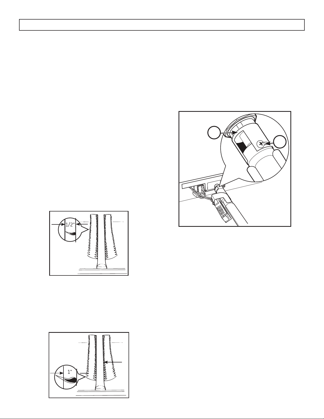
5. Adjust the oven burner air shutter
For Natural Gas: The oven burner fl ame should
be a clean, blue fl ame with distinct inner cones
approximately 1/2” long. A soft, lazy fl ame with
indistinct cones means too much gas or not enough
air. A noisy lifting fl ame means too much air.
INSTALL THE RANGE
If burner adjustment is necessary:
Loosen the lock screw located at the top of the air
shutter, then rotate the air shutter to the correct
position and retighten the screw.
1. Air shutter
2. Lock screw
For LP gas: The fl ame should have approximately
1-inch blue cones. After 30 seconds of burner
operation, check for fl ames lifting off the burner
ports. If lifting is observed, gradually reduce the air
shutter opening until fl ames are stabilized. Some
yellow tipping may be normal for LP gas.
1
2
The oven burner fl ame can be checked as follows
(without burner baffl e in place):
• To correct a yellow fl ame, increase size of air
shutter opening.
• To correct a lifting, but distinct, blue fl ame,
decrease size of air shutter opening.
The air shutter should be set approximately 2/3
open for natural gas, and approximately full open
for LP gas.
Loading ...
Loading ...
Loading ...