Loading ...
Loading ...
Loading ...
15
INSTALLATION INSTRUCTIONS
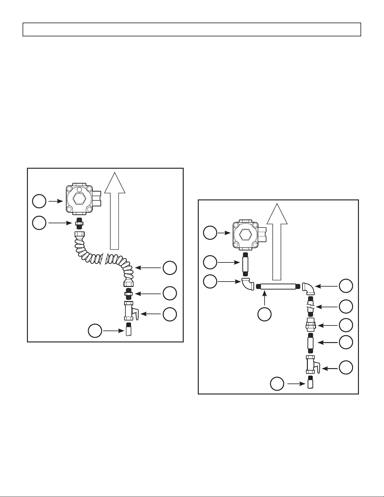
FLEXIBLE CONNECTOR HOOKUP EXAMPLE
To the installer: Inform the consumer of the location
of the gas shut-off valve and leave these instructions
with the consumer for future use.
Note: The arrow indicates the direction of gas fl ow
into the range.
1. Pressure regulator
2. Adapter
3. Flex connector (4 1/2 feet maximum)
4. Adapter
5. Gas shut off valve
6. 1/2” or 3/4” gas pipe
1
2
3
4
5
6
RIGID CONNECTOR HOOKUP EXAMPLE
To the installer: Inform the consumer of the location
of the gas shut-off valve and leave these instructions
with the consumer for future use.
Note: The arrow indicates the direction of gas fl ow
into the range.
1. Pressure regulator
2. Black iron pipe 4 1/2”
3. 90° elbow
4. Nipple (may not be required)
5. 90° elbow
6. Black iron pipe
7. Union
8. Nipple
9. Gas shut off valve
10. 1/2” or 3/4” gas pipe
1
2
4
5
6
7
8
9
10
3
INSTALL THE RANGE
3. Seal the openings
Seal any openings in the wall behind the range
and in the fl oor under the range when hookups are
completed.
Loading ...
Loading ...
Loading ...