Loading ...
Loading ...
Loading ...
English 7
Installation
Installation Instructions
We recommend that a qualied technician install the range hood. It is the
installer’s responsibility to ensure the range hood complies with the instal-
lation clearances specied for the product.
• It is recommended that the vent system be installed before the hood is
installed.
• If possible, disconnect and move freestanding or slide-in ranges from
cabinet openings to provide easier access to the rear wall.
• Before making cutouts, make sure there is proper clearance within the
ceiling or wall for the exhaust vent.
• Conrm that all installation parts have been removed from the
shipping carton.
1. Turn off the power at the circuit breaker panel or fuse box.
2. Determine which venting method to use: roof or wall exhaust.
NOTE: This hood is factory set to vent through the top air exit.
3. Select a at surface for assembling the range hood.
Place a covering over that surface.
Venting Methods
Outside Top exhaust
Vertical Duct Ø 10″ (25.4 cm)
Use the diagram or the hood as a template and mark the locations for the
door ductwork, electrical wiring and keyhole screw slots.
A
D
C
CL
B
E
FRONT OF THE HOOD
5
1
⁄4”
(13.3 cm)
WALL
5
1
⁄4”
(13.3 cm)
3
⁄4” (19 mm)
10
1
⁄2”
(26.6 cm)
NK36R9600CS
NK36R9600CM
A 36″ (91.2 cm)
B 12″ (30.5 cm)
C 1″ (2.54 cm)
D 2
5
⁄8″ (6.5 cm)
E 7
1
⁄2″ (19 cm)
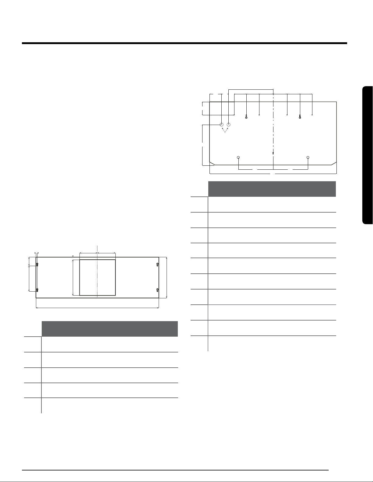
Rear Installation Diagram
Use the diagram or the hood as a template and mark the locations on the
wall for electrical wiring and keyhole screws slots.
Ø 1”
2.5 cm
B B
A
C
C
CL
D
D
E
E
F
G
H
I
TOP OF THE
HOOD
J
NK36R9600CS
NK36R9600CM
A 36″ (91.2 cm)
B 9
7
⁄8″ (25 cm)
C 4″ (10 cm)
D 3
11
⁄16″ (9.3 cm)
E 3
7
⁄16″ (8.69 cm)
F 2” (5 cm)
G 3
6
⁄16″ (8.55 cm)
H 3
13
⁄16″ (9.6 cm)
I 11
9
⁄16″ (29.32 cm)
J 12
10
⁄16″ (32 cm)
Installation
Loading ...
Loading ...
Loading ...