Loading ...
Loading ...
Loading ...
33
Wireless
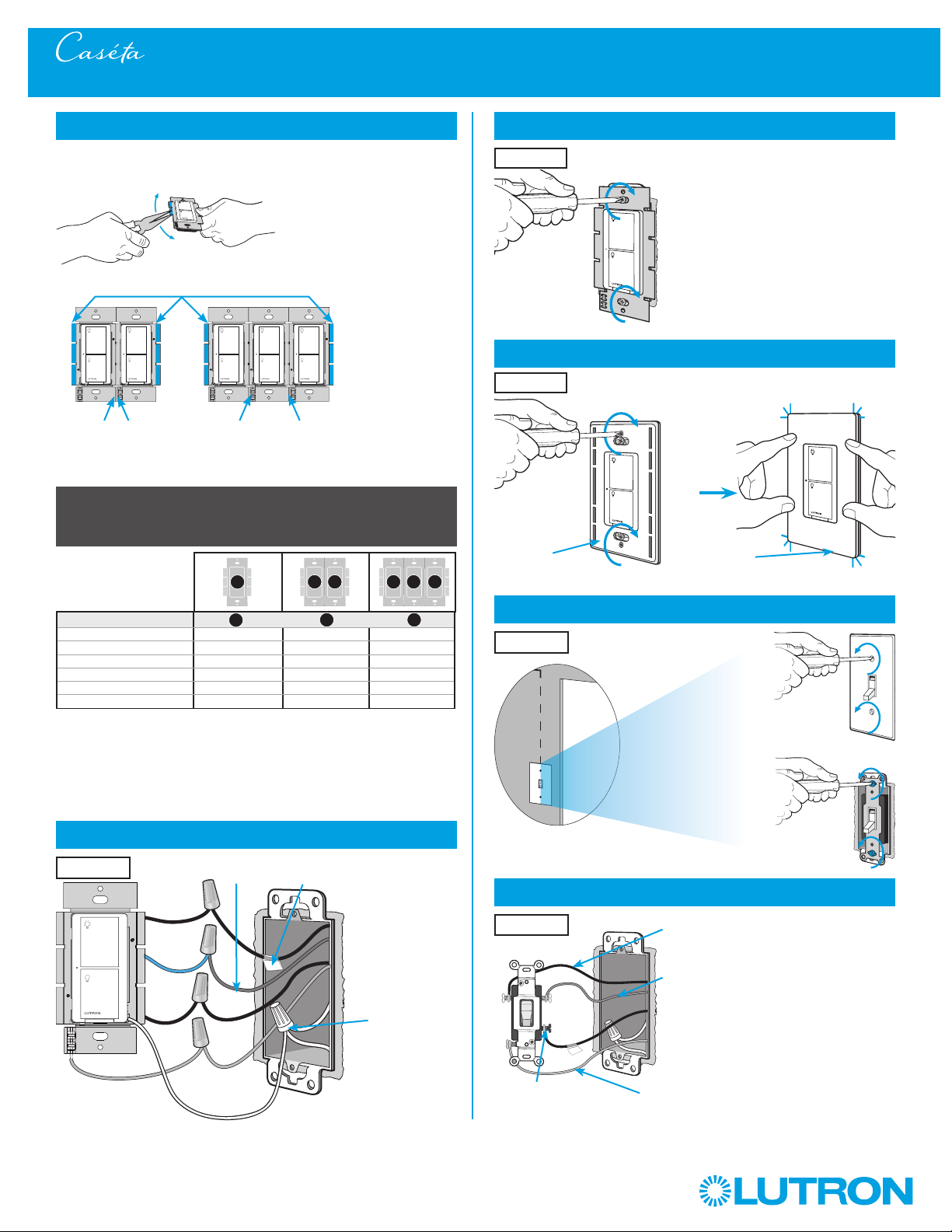
7
Remove side sections (if necessary)
8
Connect the new Caséta Wireless neutral switch
Tagged Wire
Note wire color
tied to blue wire
Ground
(Green Wire)
White
9
Mount the Caséta Wireless switch
10
Attach the wallplate
11
Remove existing toggle switch from wall at Location 2
3-Way Installation - Caséta Wireless In-Wall Neutral Switch with Mechanical Toggle Switch
12a
Modify wiring for existing toggle switch
Ground - Green / Bare Copper
(keep connected to switch)
Different Color
Screw / Tagged Wire
(disconnect from switch)
Noted wire color
from Step 8
(keep connected to switch)
When installing more than one Caséta Wireless switch in the same wallbox,
it is necessary to remove inner side sections prior to wiring. See image and
chart below for more information.
Location 2
Location 2
Location 1
Red
Blue
Black
Important note:
Removing side sections reduces the switch’s maximum wattage
rating. See the chart below for maximum wattage information.
Neutral
connection
required
1
Neutral required.
2
The maximum lamp wattage is determined by the efficiency of the transformer, with
70% – 85% as typical. For actual transformer efficiency, contact either the fixture or
transformer manufacturer. The total VA rating of the transformer(s) shall not exceed the VA
rating of the in-wall switch.
3
The in-wall switch is ULR Listed for use with all magnetic and electronic fluorescent ballasts.
B
B B
C
B
A
PD-6ANS (120 V~)
1
LED 6 A 6 A 5 A
Halogen / incandescent 720 W 720 W 600 W
Electronic Low-Voltage 720 VA 720 VA 600 VA
Magnetic Low-Voltage
2
720 VA 720 VA 600 VA
Fluorescent
3
6 A 6 A 5 A
General Purpose Fan 3.6 A 3.6 A 3.6 A
A
B C
Do not remove outside side sections
on switches at the end of gang.
Each switch has inside
side sections removed.
Switch in the middle has
all side sections removed.
‘snap’
Wallplate
Adapter
Wallplate
Location 1
Location 1
Remaining Wire
(disconnect from switch)
Loading ...
Loading ...
Loading ...