Loading ...
Loading ...
Loading ...
User Manual Page 5
Preparation
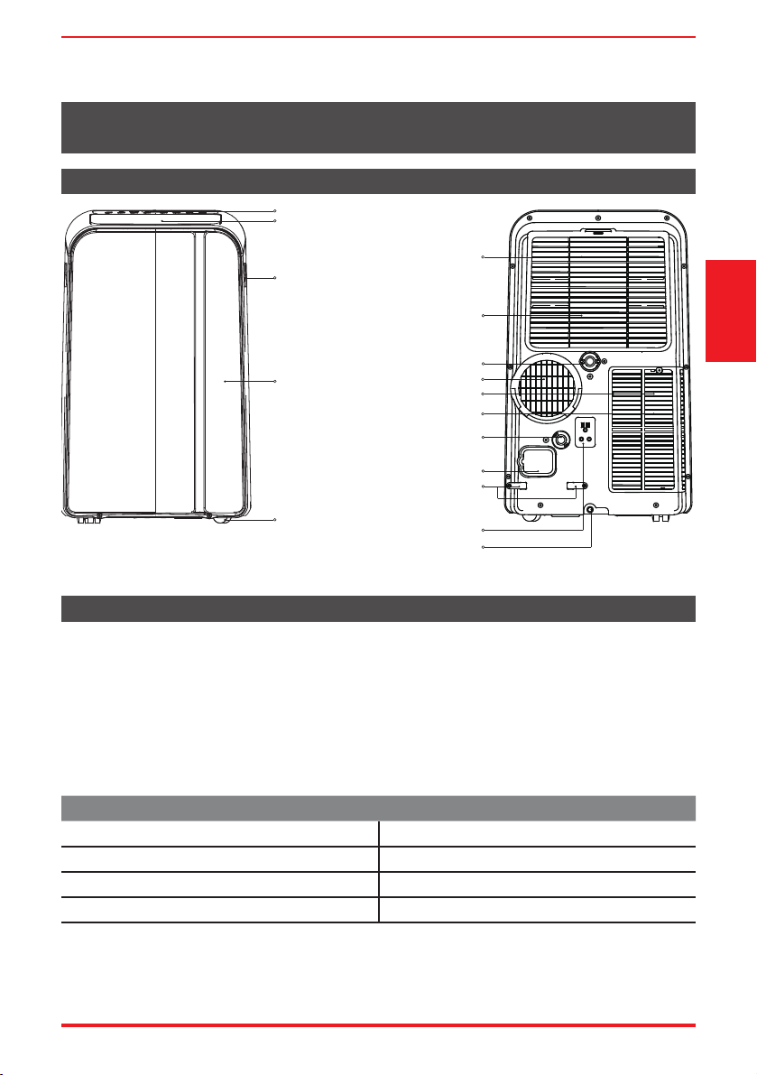
control panel
handle
(both sides)
horizontal louver
blade
(automatic swing)
Caster
power plug socket
power cord buckle
bottom tray
drain outlet
power cord outlet
drain outlet
(only for pump
heating mode)
upper air filter
(behind the grille)
upper air intake
air outlet
lower air filter
lower air intake
drain outlet
Panel
Front Rear
Design and Compliance Notes
Design Notice:
In order to ensure the optimal performance of our products, the design speci cations of the unit and
remote control are subject to change without prior notice.
Energy Rating Information:
The Energy Rating for this unit is based on an installation using an unextended exhaust duct without
adaptors A or B (as shown in the Installation section of this manual).
Unit Temperature Range:
Mode Temperature Range
Cool 17°C ~ 35°C (62°F ~ 95°F)
Dry 13°C ~ 35°C (55°F ~ 95°F)
Heat (heat pump mode) 5°C ~ 30°C (41°F ~ 86°F)
Heat (electrical heat mode) ≤ 30°C (86°F)
Exhaust Hose Installation:
The exhaust hose and adaptor must be installed or removed in accordance with the usage mode.
For COOL, HEAT (heat pump type) or AUTO mode, exhaust hose must be installed.
For FAN, DEHUMIDIFY or HEAT (electrical heat type) exhaust hose must be removed.
OPERATING INSTRUCTIONS
Operating
Instructions
Loading ...
Loading ...
Loading ...