Loading ...
Loading ...
Loading ...
Kelvinator Air Conditioning Indoor unit installation 9
Indoor unit installation
Recommended circuit breaker rating
Model Circut breaker rating (Amps)
KSV25CRH, KSV25HRH,
KSD25HRH
KSV50HRH, KSD50HRH,
KSV71CRH, KSV71HRH,
KSD71HRH
KSV35CRH, KSV35HRH,
KSD35HRH
15
15
20
25
KSV80HRG, KSD80HRG xxA
25KSV90HRH, KSD90HRH,
NOTE: The wire size of power supply cord and interconnected
wire and the current of the fuse or switch are determined by the
maximum current indicated on the nameplate which located on
the side panel of the unit. Please refer to the nameplate before
selecting the wire size, fuse or switch.
important
The air conditioners circuit board (PCB) is designed with a fuse to
provide over current protection. The spe
tions of the fuse are
printed on the circuit board, such as:
Indoor unit: T3.15A/250VAC, T5A/250VAC (applicable for unit
adopts R32 refrigerant).
Outdoor unit: T20A/250VAC (for < 5.0kW unit), T30A/250VAC
(for > 5.0kW unit)
NOTE: Ceramic body fuse.
Connect the cable to the indoor unit
NOTE: Before performing any electrical work, turn off the main
power to the system.
1. Use suitably rated power cable to connect to the indoor unit.
Note the main power supply goes to the outdoor unit and the
indoor unit does not carry full compressor current, therefore
1mm
2
(or larger) wire is suitable for connecting between indoor
unit and outdoor unit accordingly.
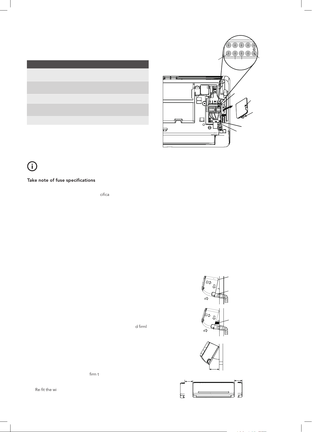
2. Lift the indoor unit panel up, remove the wire box cover by
loosening the screw.
3. Feed in the active, neutral, earth and signal wires from the
outside until the wires are visible in the indoor unit terminal
block area.
4. Remove the cable clamp. Match wire colours with terminal
numbers on indoor and outdoor unit terminal blocks an
y
screw wires to the corresponding terminals. It is recommended
to use the following wire colour sequence:
1(L) = Brown;
2(N) = Blue;
S = White;
(Earth) = Yellow & Green.
5. Connect the end of the connection cable fully inserting into
the terminal block. Tighten the terminal block screws, then
gently pull on the wires to con
hey are securely attached.
6. Fasten the connection cable with a cable clamp.
7.
re box cover and secure with the screw, then close
the indoor unit cover.
TIPS & INFORMATION
Terminal block
Terminal block
active
brown
neutral
blue
) 2(
S
1(L )N
signal
white
earth (yellow
and green)
Wire cover
Screw
Screw
Cable clamp
Fig 7.
1. Use vinyl tape to tape the power cables to the drain pipe and
hose assembly with drain hose at the bottom.
2. Carefully pass the piping and wiring assembly through the
hole, taking care to ensure that no pipe or cable touches any
sharp edge within the cut wall.
3. Hook the indoor unit onto the upper portion of installation
plate (Engage the indoor unit with the upper edge of the
installation plate). Ensure the hooks are properly seated on the
installation plate by moving it in left and right.
4. Piping can easily be made by lifting the indoor unit with a
cushioning material between the indoor unit and the wall.
Get it out after nish piping. When use a wall embedded pipe,
the in
door unit can be moved to the left or right for 30–50mm
(model dependent), which offers sufcient space to arrange
the pipes and ensure the indoor unit fully close to the wall
after installation.
5. Press the lower left and right side of the unit against the
installation plate until hooks engages with the their slots.
Fig 8.
Upper hook
Lower hook
Cushioning
material
Wall embedded
pipe
Move to left or right
30°
150mm
30-50mm 30-50mm
Loading ...
Loading ...
Loading ...