Loading ...
Loading ...
Loading ...
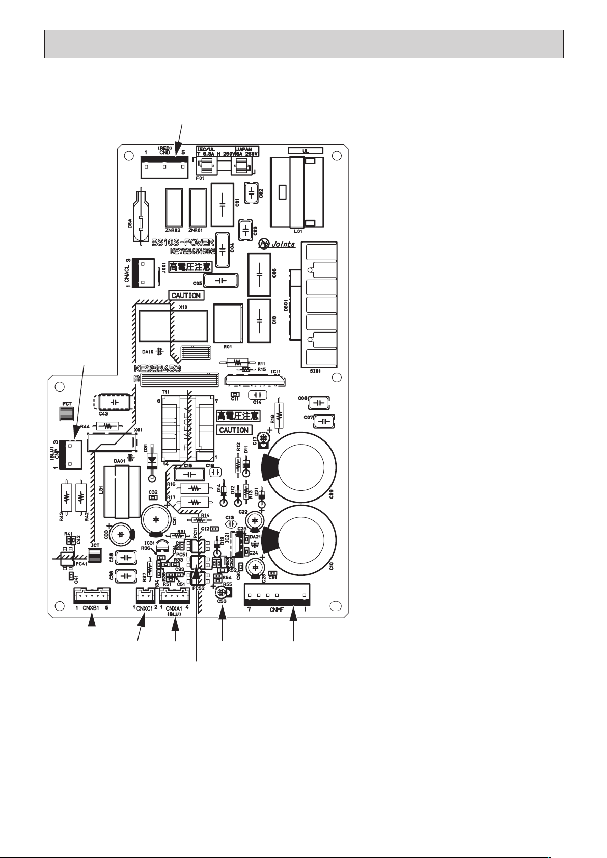
CND
CNXB1 CNXC1
CNXA1 CNMF
PC51
(*1)
C53
(*1)
CNP
CND Power supply voltage (220 - 240VAC)
CNMF Fan motor output
1 - 4: 310 - 340 VDC
5 - 4: 15 VDC
6 - 4: 0 - 6.5 VDC
7 - 4: Stop 0 or 15 VDC
Run 7.5 VDC
(0 - 15 pulse)
CNP Drain-up mechanism output (200VAC)
CNXA1
Connect to the indoor controller board
CNXB1
Connect to the indoor controller board
CNXC1
Connect to the indoor controller board
CNXA2
Connect to the indoor power board
CNXB2
Connect to the indoor power board
CNXC2
Connect to the indoor power board
(*1)
V
FG
Voltage on the (-) side of PC51 and
C25
(Same with the voltage between 7 (+)
and 4 (-) of CNMF)
V
CC
Voltage between the C25 pins 15
VDC
(Same with the voltage between 5 (+)
and 4 (-) of CNMF)
V
sp Voltage between the C53 pins
0VDC (with the fan stopped)
1 - 6.5VDC (with the fan in operation)
(Same with the voltage between 6 (+)
and 4 (-) of CNMF)
31
9-5. TEST POINT DIAGRAM
9-5-1. Power supply board
HWE1309A.qx 3/18/14 10:11 AM Page 31
Loading ...
Loading ...
Loading ...