Loading ...
Loading ...
Loading ...
23
Wireless remote controller
(1) Turn on the power to the unit at least 12 hours before the test run.
(2) Press the TEST RUN button
AA
twice continuously.
(Start this operation from the status of remote controller display turned off.)
and current operation mode are displayed.
(3) Press the MODE button
BB
to activate COOL mode, then check whether cool air is blown out from the unit.
(4) Press the MODE button
BB
to activate HEAT mode, then check whether warm air is blown out from the unit.
(5) Press the FAN button
CC
and check whether fan speed changes.
(6) Press the VANE button
DD
and check whether the auto vane operates properly.
(7) Press the ON/OFF button to stop the test run.
Note:
• Point the remote controller towards the indoor unit receiver while following steps (2) to (7).
• It is not possible to run the in FAN, DRY or AUTO mode.
TEST RUN
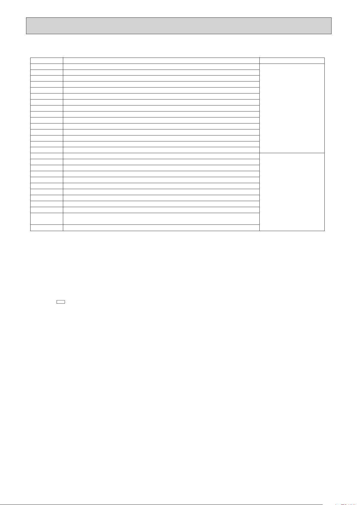
1 Check code Symptom Remark
P1 Intake sensor error
P2 Pipe (TH2) sensor error
P9 Pipe (TH5) sensor error
E6,E7 Indoor/outdoor unit communication error
P4 Drain sensor error
P5
PA
PB
Drain pump error
Forced compressor error
Fan motor error
P6 Freezing/Overheating safeguard operation
EE Communication error between indoor and outdoor units
P8
E4
Fb
Pipe temperature error
Remote controller signal receiving error
E0, E3 Remote controller transmission error
E1, E2 Remote controller control board error
E9
Indoor unit control system error (memory error, etc.)
Indoor/outdoor unit communication error (Transmitting error) (Outdoor unit)
UP Compressor overcurrent interruption
U3,U4 Open/short of outdoor unit thermistors
UF Compressor overcurrent interruption (When compressor locked)
U2 Abnormal high discharging temperature/49C worked/insufficient refrigerant
U1,Ud Abnormal high pressure (63H worked)/Overheating protection operation
U5 Abnormal temperature of heat sink
U8 Outdoor unit fan safeguard stop
U6 Compressor overcurrent interruption/Abnormal of power module
U7 Abnormality of super heat due to low discharge temperature
U9,UH Abnormality such as overvoltage or voltage shortage and abnormal synchronous signal to main circuit/
Current sensor error
Others Other errors (Refer to the technical manual for the outdoor unit.)
For details, check the LED display
of the outdoor controller board.
As for outdoor unit, refer to
service manual.
Each unit has two each of the
following: intake sensors, liquid
pipe sensors, 2-phase pipe
sensors, and fan motors. When
a problem occurs with one of
any of the items above, an error
code (P1, P2, P8, P9, or PB)
will appear. When an error code
appears, check both of the items.
• On wired remote controller.
1 Check code displayed in the LCD.
• For description of each check code, refer to the following table.
HWE1309A.qx 3/18/14 10:11 AM Page 23
Loading ...
Loading ...
Loading ...