Loading ...
Loading ...
Loading ...
19
Min.300mm
Min.500mm
Min.500mm
Min.300mm
425
685
200 585 50
1754
200 585
0~150
200
200
1304
1304
400
400
0~150
400
400
25
25
75
75
(450x450)
(450x450)
Drain pan Drain pan
Maintenance access space Maintenance access space
Maintenance access space
When connecting inlet duct.
When installing the suspension fixtures prior to
installation of the indoor unit without inlet duct.
When hanging the indoor unit directly without inlet duct.
When connecting inlet duct.
When installing the suspension fixtures prior to
installation of the indoor unit without inlet duct.
When hanging the indoor unit directly without inlet duct.
Ceiling Ceiling
Ceiling Ceiling
Access door 2 Access door 3
Access door 1
Access door 1
Access door 2
Access door 3
Access door 2 Access door 3
Ceiling beam
Ceiling beam
Intake air Intake air
Intake air
Intake air
Supply air Supply air
Supply air
Bottom of indoor unit
Bottom of indoor unit
Supply air
Electric box
Electric box
Electric box Electric box
Electric box
Electric box
B
C
Fig.2
Fig.5
Fig.3
Fig.6
(Viewed from the direction of the arrow B)
(Viewed from the direction of the arrow C)
Fig.1
Fig.4
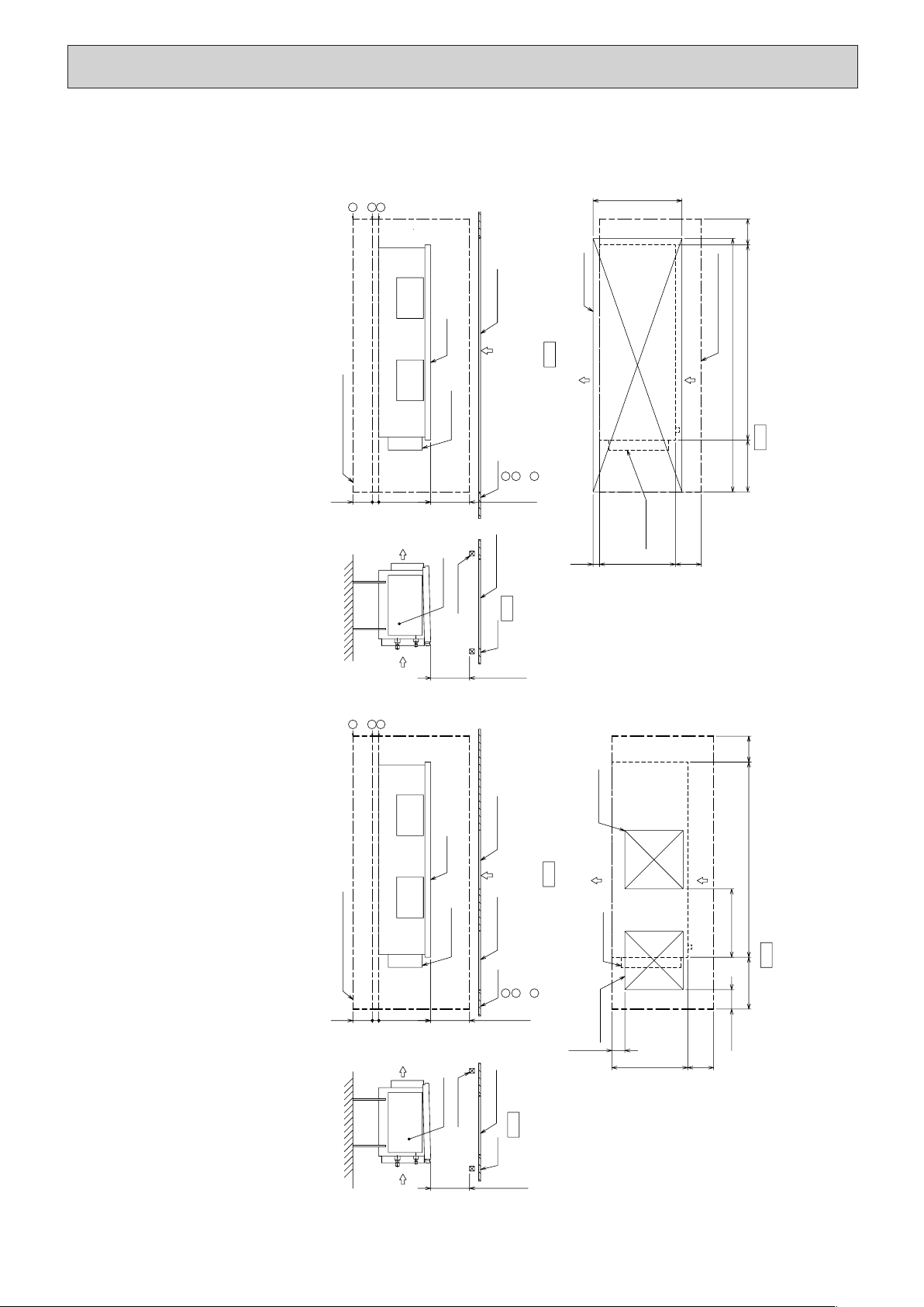
[Maintenance access space]
Secure enough access space to allow for the maintenance, inspection, and replacement of the motor, fan, drain pan, heat exchanger,
and electric box in one of the following ways.
Select an installation site for the indoor unit so that its maintenance access space will not be obstructed by beams or other objects.
(1) When a space of 500mm or more is available below the unit between the unit and the ceiling. (Fig.1)
· Create access door 1 and 2 (450x450mm each) as shown in Fig.3.
(Access door 2 is not required if enough space is available below the unit for a maintenance worker to work in.)
· An access hole of the same size as the access door 3 as shown in Fig. 6 is required to access drain pan or heat exchanger for replacement.
(Required only when the ceiling material cannot be removed)
(2) When a space of less than 500mm is available below the unit between the unit and the ceiling.
(At least 300mm of space should be left below the unit as shown in Fig.4.)
· Create access door 3 below the electric box and the unit as shown in Fig.6.
1
2
3
1
2
3
1
2
3
1
2
3
HWE1309A.qx 3/18/14 10:11 AM Page 19
Loading ...
Loading ...
Loading ...