1500/2500/3500
OWNER’S MANUAL
2015
2015 RAM TRUCK 1500/2500/3500
15D241-126-AG Seventh Edition Printed in U.S.A.
RAM TRUCK
FCA US LLC

VEHICLES SOLD IN CANADA
With respect to any Vehicles Sold in Canada, the name FCA
US LLC shall be deemed to be deleted and the name FCA
Canada Inc. used in substitution therefore.
DRIVING AND ALCOHOL
Drunken driving is one of the most frequent causes of
accidents.
Your driving ability can be seriously impaired with blood
alcohol levels far below the legal minimum. If you are
drinking, don’t drive. Ride with a designated non-
drinking driver, call a cab, a friend, or use public trans-
portation.
WARNING!
Driving after drinking can lead to an accident.
Your perceptions are less sharp, your reflexes are
slower, and your judgment is impaired when you
have been drinking. Never drink and then drive.
This manual illustrates and describes the operation of
features and equipment that are either standard or op-
tional on this vehicle. This manual may also include a
description of features and equipment that are no longer
available or were not ordered on this vehicle. Please
disregard any features and equipment described in this
manual that are not on this vehicle.
FCA US LLC reserves the right to make changes in design
and specifications, and/or make additions to or improve-
ments to its products without imposing any obligation
upon itself to install them on products previously manu-
factured.
Copyright © 2016 FCA US LLC

TABLE OF CONTENTS
SECTION PAGE
1
INTRODUCTION . ..............................................................3
2
THINGS TO KNOW BEFORE STARTING YOUR VEHICLE ..................................9
3
UNDERSTANDING THE FEATURES OF YOUR VEHICLE . . . ..............................119
4
UNDERSTANDING YOUR INSTRUMENT PANEL ......................................281
5
STARTINGANDOPERATING ....................................................443
6
WHATTODOINEMERGENCIES..................................................695
7
MAINTAININGYOURVEHICLE...................................................759
8
MAINTENANCE SCHEDULES ....................................................843
9
IF YOU NEED CONSUMER ASSISTANCE ............................................853
10
INDEX .....................................................................863
1
2
3
4
5
6
7
8
9
10



INTRODUCTION
Congratulations on selecting your new FCA US LLC
vehicle. Be assured that it represents precision workman-
ship, distinctive styling, and high quality - all essentials
that are traditional to our vehicles.
This Owner’s Manual has been prepared with the assis-
tance of service and engineering specialists to acquaint
you with the operation and maintenance of your vehicle.
It is supplemented by Warranty Information, and various
customer-oriented documents. Please take the time to
read these publications carefully. Following the instruc-
tions and recommendations in this manual will help
assure safe and enjoyable operation of your vehicle.
NOTE: After reviewing the owner information, it
should be stored in the vehicle for convenient referenc-
ing and remain with the vehicle when sold.
When it comes to service, remember that your authorized
dealer knows your vehicle best, has factory-trained tech-
nicians and genuine MOPAR® parts, and cares about
your satisfaction.
RAM is a registered trademark of FCA US LLC.
HOW TO USE THIS MANUAL
Consult the Table of Contents to determine which section
contains the information you desire.
Since the specification of your vehicle depends on the
items of equipment ordered, certain descriptions and
illustrations may differ from your vehicle’s equipment.
The detailed index at the back of this Owner’s Manual
contains a complete listing of all subjects.
Consult the following table for a description of the
symbols that may be used on your vehicle or throughout
this Owner’s Manual:
4 INTRODUCTION

1
INTRODUCTION 5

WARNINGS AND CAUTIONS
This Owner’s Manual contains WARNINGS against
operating procedures that could result in a collision or
bodily injury. It also contains CAUTIONS against proce-
dures that could result in damage to your vehicle. If you
do not read this entire Owner’s Manual, you may miss
important information. Observe all Warnings and Cau-
tions.
VAN CONVERSIONS/CAMPERS
The New Vehicle Limited Warranty does not apply to
body modifications or special equipment installed by van
conversion/camper manufacturers/body builders. Refer
to the Warranty Information book, Section 2.1.C. Such
equipment includes video monitors, VCRs, heaters,
stoves, refrigerators, etc. For warranty coverage and
service on these items, contact the applicable manufac-
turer.
Operating instructions for the special equipment in-
stalled by the conversion/camper manufacturer should
also be supplied with your vehicle. If these instructions
are missing, please contact your authorized dealer for
assistance in obtaining replacement documents from the
applicable manufacturer.
For information on the Body Builders Guide refer to:
www.rambodybuilder.com. This website contains di-
mensional and technical specifications for your vehicle. It
is intended for Second Stage Manufacturer’s technical
support. For service issues, contact your authorized
dealer.
VEHICLE IDENTIFICATION NUMBER
The Vehicle Identification Number (VIN) is found on the
left front corner of the instrument panel, visible through
the windshield. This number also appears on the vehicle
6 INTRODUCTION
frame and underbody as well as the Automobile Infor-
mation Disclosure Label affixed to a window on your
vehicle, the vehicle registration and title.
NOTE: It is illegal to remove or alter the VIN.
VEHICLE MODIFICATIONS/ALTERATIONS
WARNING!
Any modifications or alterations to this vehicle could
seriously affect its roadworthiness and safety and
may lead to a collision resulting in serious injury or
death.
Vehicle Identification Number
1
INTRODUCTION 7


THINGS TO KNOW BEFORE STARTING YOUR VEHICLE
CONTENTS
䡵 A WORD ABOUT YOUR KEYS .............12
▫ Ignition Node Module (IGNM) ............12
▫ Keyless Push Button Ignition — If Equipped . . .13
▫ KeyFob.............................14
▫ Removing Key Fob From Ignition ..........16
▫ Key-In-Ignition Reminder ................18
䡵 SENTRY KEY® .........................18
▫ Replacement Keys .....................19
▫ Customer Key Programming ..............20
▫ General Information ....................20
䡵 VEHICLE SECURITY ALARM ..............21
▫ Rearming Of The System .................21
▫ To Arm The System.....................21
▫ To Disarm The System ...................22
▫ Security System Manual Override ...........23
䡵 ILLUMINATED APPROACH ...............23
䡵 REMOTE KEYLESS ENTRY (RKE) ...........24
▫ Remote Unlock The Doors ...............26
▫ To Lock The Doors .....................27
▫ Sound Horn With Remote Key Lock .........27
2

▫ Using The Panic Alarm ..................28
▫ RKE Air Suspension (Remote Lowering Of The
Vehicle) — If Equipped ..................28
▫ Programming Additional Transmitters........30
▫ Transmitter Battery Replacement ...........30
▫ General Information ....................33
䡵 REMOTE STARTING SYSTEM — IF EQUIPPED .34
▫ How To Use Remote Start ................34
䡵 DOOR LOCKS .........................37
▫ Manual Door Locks .....................37
▫ Power Door Locks — If Equipped ..........38
▫ Child-Protection Door Lock ...............40
䡵 KEYLESS ENTER-N-GO™ .................42
䡵 WINDOWS ...........................46
▫ Power Windows — If Equipped ...........46
▫ Wind Buffeting .......................49
䡵 OCCUPANT RESTRAINT SYSTEMS ..........49
▫ Important Safety Precautions ..............50
▫ Seat Belt Systems ......................51
▫ Supplemental Restraint System (SRS) ........67
▫ Child Restraints .......................82
▫ Transporting Pets .....................113
10 THINGS TO KNOW BEFORE STARTING YOUR VEHICLE

䡵 ENGINE BREAK-IN RECOMMENDATIONS . . .113
䡵 SAFETY TIPS .........................114
▫ Transporting Passengers .................114
▫ Exhaust Gas .........................115
▫ Safety Checks You Should Make Inside The
Vehicle .............................116
▫ Periodic Safety Checks You Should Make Outside
The Vehicle .........................118
2
THINGS TO KNOW BEFORE STARTING YOUR VEHICLE 11

A WORD ABOUT YOUR KEYS
Your vehicle uses either a key start ignition system or
keyless ignition system. The key start ignition system
consists of a either a bladed key with an immobilizer chip
in it, or a Key Fob with Remote Keyless Entry (RKE)
transmitter and an Ignition Node Module (IGNM). The
keyless ignition system consists of a Key Fob with
Remote Keyless Entry (RKE) transmitter and a Keyless
Push Button Ignition.
Ignition Node Module (IGNM)
The Ignition Node Module (IGNM) operates similar to an
ignition switch. It has four operating positions, three with
detents and one that is spring-loaded. The detent posi-
tions are OFF, ACC, and ON/RUN. The START position
is a spring-loaded momentary contact position. When
released from the START position, the switch automati-
cally returns to the ON/RUN position.
Ignition Module
1 — OFF
2 — ACC (ACCESSORY)
3 — ON/RUN
4 — START
12 THINGS TO KNOW BEFORE STARTING YOUR VEHICLE

Keyless Push Button Ignition — If Equipped
This feature allows the driver to operate the ignition switch
with the push of a button as long as the Remote Keyless
Entry (RKE) transmitter is in the passenger compartment.
The Keyless Push Button Ignition has four operating
positions; three of which are labeled and will illuminate
when in position. The three positions are OFF, ACC, and
ON/RUN. The fourth position is START, during start
RUN will illuminate.
NOTE: In case the ignition switch does not change with
the push of a button, the RKE transmitter (Key Fob) may
have a low or dead battery. In this situation, a back up
method can be used to operate the ignition switch. Put
the nose side (side opposite of the emergency key) of the
Key Fob against the ENGINE START/STOP button and
push to operate the ignition switch and with your foot
applied on the brake pedal.
Keyless Push Button Ignition
1 — OFF
2 — ACC (ACCESSORY)
3 — ON/RUN
2
THINGS TO KNOW BEFORE STARTING YOUR VEHICLE 13

Key Fob
Key Fob — If Equipped
The Key Fob operates the ignition switch. Insert the
square end of the key fob into the ignition switch located
on the instrument panel and rotate to the desired posi-
tion. It also contains the Remote Keyless Entry (RKE)
transmitter and an emergency key, which stores in the
rear of the Key Fob.
The emergency key allows for entry into the vehicle
should the battery in the vehicle or the RKE transmitter
go dead. You can keep the emergency key with you when
valet parking.
To remove the emergency key, slide the mechanical latch
at the top of the Key Fob sideways with your thumb and
then pull the key out with your other hand.
NOTE: When using the emergency key to gain access to
your vehicle, be aware that the security alarm may be
triggered. Insert the Key Fob into the ignition and place
the ignition in the ON/RUN mode to disarm the security
system.
Emergency Key Removal
14 THINGS TO KNOW BEFORE STARTING YOUR VEHICLE

Keyless Push Button Ignition Key Fob — If Equipped
This Keyless Push Button Ignition Key Fob allows the
driver to operate the ignition switch with the push of a
button, as long as the Remote Keyless Entry (RKE)
transmitter is in the passenger compartment. The Keyless
Push Button Ignition has four operating positions, three
of which are labeled and will illuminate when in posi-
tion. The three positions are OFF, ACC, and ON/RUN.
The fourth position is START, during start RUN will
illuminate. It also contains the Remote Keyless Entry
(RKE) transmitter and an emergency key, which stores in
the rear of the Key Fob.
The emergency key allows for entry into the vehicle
should the battery in the vehicle or the RKE transmitter
go dead. You can keep the emergency key with you when
valet parking.
To remove the emergency key, slide the mechanical latch
on the backside of the Key Fob sideways with your
thumb and then pull the key out with your other hand.
NOTE: When using the emergency key to gain access to
your vehicle, be aware that the security alarm may be
triggered. Insert the Key Fob into the ignition and place
the ignition in the ON/RUN mode to disarm the security
system.
Emergency Key Removal Keyless Enter-N-Go™ Fob
2
THINGS TO KNOW BEFORE STARTING YOUR VEHICLE 15
NOTE: You can insert the double-sided emergency key
into the door lock cylinder with either side up.
Removing Key Fob From Ignition
Place the shift lever in PARK (if equipped with an
automatic transmission). Turn the Key Fob to the OFF
position and then remove the Key Fob.
NOTE:
• The power window switches, radio, power sunroof (if
equipped), and power outlets will remain active for up
to 10 minutes after the ignition switch is turned to the
OFF position. Opening either front door will cancel
this feature. Refer to “Uconnect® Settings” in “Under-
standing Your Instrument Panel” for further informa-
tion.
• For vehicles not equipped with a touchscreen radio,
refer to “Electronic Vehicle Information Center
(EVIC)/ Settings (Customer-Programmable Features)”
in “Understanding Your Instrument Panel” for further
information.
• For vehicles equipped with a touchscreen radio, refer
to “Uconnect® Settings” in “Understanding Your In-
strument Panel” for further information.
CAUTION!
• If your vehicle battery becomes low or dead, your
Key Fob will become locked in the ignition.
• Do not attempt to remove the Key Fob while in this
condition, damage could occur to the Key Fob or
ignition module. Only remove the emergency key
for locking and unlocking the doors.
• Leave the Key Fob in the ignition and either:
• Jump Start the vehicle.
• Charge the battery.
16 THINGS TO KNOW BEFORE STARTING YOUR VEHICLE
WARNING!
• Never use the PARK position as a substitute for the
parking brake. Always apply the parking brake
fully when parked to guard against vehicle move-
ment and possible injury or damage.
• When leaving the vehicle, always remove the key
fob from the ignition and lock your vehicle. If
equipped with Keyless Enter-N-Go, always make
sure the keyless ignition node is in “OFF” mode,
remove the Key Fob from the vehicle and lock the
vehicle.
• Never leave children alone in a vehicle, or with
access to an unlocked vehicle.
• Allowing children to be in a vehicle unattended is
dangerous for a number of reasons. A child or
(Continued)
WARNING! (Continued)
others could be seriously or fatally injured. Chil-
dren should be warned not to touch the parking
brake, brake pedal or the gear selector.
• Do not leave the Key Fob in or near the vehicle, or
in a location accessible to children, and do not
leave the ignition of a vehicle equipped with
Keyless Enter-N-Go in the ACC or ON/RUN mode.
A child could operate power windows, other con-
trols, or move the vehicle.
• Do not leave children or animals inside parked
vehicles in hot weather. Interior heat build-up may
cause serious injury or death.
2
THINGS TO KNOW BEFORE STARTING YOUR VEHICLE 17
CAUTION!
An unlocked car is an invitation to thieves. Always
remove the key from the ignition and lock all doors
when leaving the vehicle unattended.
Key-In-Ignition Reminder
Opening the driver’s door when the Key Fob is in the
ignition and the ignition switch position is OFF or ACC,
a chime will sound to remind you to remove the Key Fob.
NOTE:
• ⬙Keyed⬙ Ignition systems will chime in OFF or ACC
when the driver door is open.
• “Keyless⬙ Ignition systems will chime in ACC or RUN
when the driver door is open.
• If equipped with Electronic Vehicle Information Center
(EVIC)/Driver Information Display (DID), the EVIC or
DID will display “Key In Ignition.”
SENTRY KEY®
The Sentry Key® Immobilizer System prevents unau-
thorized vehicle operation by disabling the engine. The
system does not need to be armed or activated. Operation
is automatic, regardless of whether the vehicle is locked
or unlocked.
The system uses a Key Fob with a factory-mated Remote
Keyless Entry (RKE) transmitter, an Ignition Node Mod-
ule, Keyless Push Button Ignition and a RF receiver to
prevent unauthorized vehicle operation. Therefore, only
Key Fobs that are programmed to the vehicle can be used
to start and operate the vehicle. The system will not allow
the engine to crank if an invalid Key Fob is used to start
18 THINGS TO KNOW BEFORE STARTING YOUR VEHICLE
and operate the vehicle. The system will shut the engine
off in two seconds if an invalid Key Fob is used to start
the engine.
NOTE: A Key Fob that has not been programmed is also
considered an invalid key.
During normal operation, after turning on the ignition
switch, the Vehicle Security Light will turn on for three
seconds for a bulb check. If the light remains on after the
bulb check, it indicates that there is a problem with the
electronics. In addition, if the light begins to flash after
the bulb check, it indicates that someone used an invalid
Key Fob to try to start the engine. Either of these
conditions will result in the engine being shut off after
two seconds.
If the Vehicle Security Light turns on during normal
vehicle operation (vehicle running for longer than 10
seconds), it indicates that there is a fault in the electron-
ics. Should this occur, have the vehicle serviced as soon
as possible by an authorized dealer.
CAUTION!
The Sentry Key® Immobilizer system is not compat-
ible with some aftermarket remote starting systems.
Use of these systems may result in vehicle starting
problems and loss of security protection.
All of the Key Fobs provided with your new vehicle have
been programmed to the vehicle electronics.
Replacement Keys
NOTE: Only Key Fobs that are programmed to the
vehicle electronics can be used to start and operate the
vehicle. Once a Key Fob is programmed to a vehicle, it
cannot be programmed to any other vehicle.
2
THINGS TO KNOW BEFORE STARTING YOUR VEHICLE 19
CAUTION!
• Always remove the Key Fobs from the vehicle and
lock all doors when leaving the vehicle unat-
tended.
• For vehicles equipped with Keyless Enter-N-Go™,
always remember to place the ignition in the OFF
position.
NOTE: Duplication of Key Fobs may be performed at an
authorized dealer. This procedure consists of program-
ming a blank Key Fob to the vehicle electronics. A blank
Key Fob is one that has never been programmed.
When having the Sentry Key® Immobilizer System ser-
viced, bring all vehicle keys with you to an authorized
dealer.
Customer Key Programming
Programming Key Fobs or RKE transmitters may be
performed at an authorized dealer.
General Information
The Sentry Key® system complies with FCC rules part 15
and with RSS-210 of Industry Canada. Operation is
subject to the following conditions:
• This device may not cause harmful interference.
• This device must accept any interference that may be
received, including interference that may cause unde-
sired operation.
NOTE: Changes or modifications not expressly approved
by the party responsible for compliance could void the
user’s authority to operate the equipment.
20 THINGS TO KNOW BEFORE STARTING YOUR VEHICLE

VEHICLE SECURITY ALARM
The Vehicle Security Alarm monitors the vehicle doors
and ignition for unauthorized operation. When the Ve-
hicle Security Alarm is activated, interior switches for
door locks are disabled. The system provides both au-
dible and visible signals for the first three minutes the
horn will sound and the headlights will turn on, the park
lamps and/or turn signals will flash and Vehicle Security
Light will flash repeatedly. For an additional 15 minutes
only, the headlights will turn on, the park lamps and/or
turn signals, and Vehicle Security Light will flash.
Rearming Of The System
The Vehicle Security Alarm will rearm itself after the 15
additional minutes of headlights and Vehicle Security
Light flashing, if the system has not been disabled. If the
condition which initiated the alarm is still present, the
system will ignore that condition and monitor the re-
maining doors and ignition.
To Arm The System
Follow these steps to arm the Vehicle Security Alarm:
1. Remove the key from the ignition system (refer to
⬙Starting Procedures⬙ in ⬙Starting And Operating⬙ for
further information).
• For vehicles equipped with Keyless Enter-N-Go™,
make sure the vehicle ignition system is ⬙OFF.⬙
• For vehicles not equipped with Keyless Enter-N-
Go™, make sure the vehicle ignition system is ⬙OFF⬙
and the key is physically removed from the ignition.
2. Perform one of the following methods to lock the
vehicle:
• Push LOCK on the interior power door lock switch
with the driver and/or passenger door open.
• Push the LOCK button on the exterior Passive Entry
Door Handle with a valid Key Fob available in the
2
THINGS TO KNOW BEFORE STARTING YOUR VEHICLE 21

same exterior zone (refer to ⬙Keyless Enter- N-Go™⬙
in ⬙Things To Know Before Starting Your Vehicle⬙ for
further information).
• Push the LOCK button on the Remote Keyless Entry
(RKE) transmitter.
3. If any doors are open, close them.
The Vehicle Security Alarm will set when you use the
power door locks, or use the Remote Keyless Entry (RKE)
transmitter to lock the doors. After all the doors are
locked and closed, the Vehicle Security Light, in the
instrument panel cluster, will flash rapidly for about 16
seconds to indicate that the alarm is being set. After the
alarm is set, the Vehicle Security Light will flash at a
slower rate to indicate that the system is armed.
To Disarm The System
The Vehicle Security Alarm can be disarmed using any of
the following methods:
1. Push the UNLOCK button on the Remote Keyless
Entry (RKE) transmitter.
2. Grasp the Passive Entry Unlock Door Handle with a
valid Key Fob within 5 ft (1.5 m) of the passive entry
door handle (if equipped, refer to ⬙Keyless Enter-N-
Go™⬙ in ⬙Things To Know Before Starting Your Ve-
hicle⬙ for further information).
3. Cycle the vehicle ignition system out of the OFF
position.
• For vehicles equipped with Keyless Enter-N-Go™,
push the Keyless Enter-N-Go™ Start/ Stop button
(requires at least one valid Key Fob in the vehicle).
• For vehicles not equipped with Keyless Enter-N-
Go™, insert a valid key into the ignition switch and
turn the key to the ON position.
22 THINGS TO KNOW BEFORE STARTING YOUR VEHICLE

The Vehicle Security Alarm is designed to protect your
vehicle. However, you can create conditions where the
system will give you a false alarm. If one of the previ-
ously described arming sequences has occurred, the
Vehicle Security Alarm will arm regardless of whether
you are in the vehicle or not. If you remain in the vehicle
and open a door, the alarm will sound. If this occurs,
disarm the Vehicle Security Alarm.
If the Vehicle Security Alarm is armed and the battery
becomes disconnected, the Vehicle Security Alarm will
remain armed when the battery is reconnected; the
exterior lights will flash, and the horn will sound. If this
occurs, disarm the Vehicle Security Alarm.
Security System Manual Override
The Vehicle Security Alarm will not arm if you lock the
doors using the manual door lock plunger.
ILLUMINATED APPROACH
The courtesy lights will turn on when you use the
Remote Keyless Entry (RKE) transmitter to unlock the
doors or open any door.
This feature also turns on the approach lighting in the
outside mirrors (if equipped). Refer to “Mirrors” in
“Understanding The Features Of Your Vehicle” for fur-
ther information.
The lights will fade to off after approximately 30 seconds,
or they will immediately fade to off once the ignition
switch is turned to ON/RUN from the OFF position.
The front courtesy overhead console and door courtesy
lights will not turn off if the dimmer control is in the
“Dome ON” position (rotate horizontal thumb wheel on
the bottom of the switch to the far right detent position).
2
THINGS TO KNOW BEFORE STARTING YOUR VEHICLE 23

The illuminated entry system will not operate if the
dimmer control is in the “Dome OFF” position (rotate
horizontal thumb wheel on the bottom of the switch to
the far left detent position).
NOTE: If your vehicle is equipped with illuminated
approach lights under the outside mirrors, they can be
turned off by using the Electronic Vehicle Information
Center (EVIC) or Driver Information Display (DID) con-
trols (if NOT equipped with a touchscreen radio) or the
Uconnect® radio (if equipped with a touchscreen radio).
For further information, refer to “EVIC/DID” or
“Uconnect® Settings” in “Understanding Your Instru-
ment Panel.”
REMOTE KEYLESS ENTRY (RKE)
The RKE system allows you to lock or unlock all doors,
tailgate, and the RamBox® (if equipped) as well as
activate the Panic Alarm from distances up to approxi-
mately 66 ft (20 m) using a hand-held radio transmitter
with integrated key. The transmitter does not need to be
pointed at the vehicle to activate the system. Push and
release the LOCK button on the RKE transmitter to lock
all doors, the tailgate and the RamBox® (if equipped).
The turn signal lights will flash and the horn will chirp to
acknowledge the signal.
NOTE: Inserting the Key Fob with RKE transmitter into
the ignition switch disables the system from responding
to any button pushes from that RKE transmitter. Driving
at speeds 5 mph (8 km/h) and above disables the system
from responding to all RKE transmitter buttons for all
RKE transmitters.
24 THINGS TO KNOW BEFORE STARTING YOUR VEHICLE

Key Fob With Remote Keyless Entry (RKE) Transmitter
(IGNM)
Key Fob With RKE Transmitter Keyless Enter-N-Go™
Fob (KIN)
2
THINGS TO KNOW BEFORE STARTING YOUR VEHICLE 25

Remote Unlock The Doors
Push and release the UNLOCK button on the RKE
transmitter once to unlock the driver’s door. Push the
unlock button twice within five seconds to unlock all
doors, the tailgate and the RamBox® (if equipped). The
turn signal lights will flash to acknowledge the unlock
signal. The illuminated entry system will also turn on.
NOTE: The EVIC/DID or Uconnect® Settings are setup
for driver door first, otherwise this will unlock all doors.
Remote Key Unlock, Driver Door/All Doors First
This feature lets you program the system to unlock either
the driver’s door or all doors on the first push of the
UNLOCK button on the RKE transmitter. To change the
current setting, proceed as follows:
• For vehicles not equipped with a touchscreen radio,
refer to “Electronic Vehicle Information Center
(EVIC)/ Settings (Customer-Programmable Features)”
in “Understanding Your Instrument Panel” for further
information.
• For vehicles equipped with a touchscreen radio, refer
to “Uconnect® Settings” in “Understanding Your In-
strument Panel” for further information.
NOTE: Pushing the LOCK button on the RKE transmitter
while you are inside the vehicle will activate the Vehicle
Security Alarm System. Opening a door with the Vehicle
Security Alarm System activated will cause the alarm to
sound. Push the UNLOCK button to deactivate the
Vehicle Security Alarm System.
26 THINGS TO KNOW BEFORE STARTING YOUR VEHICLE

Flash Lamps With Remote Key Lock
This feature will cause the turn signal lights to flash when
the doors are locked or unlocked with the RKE transmit-
ter. This feature can be turned on or turned off. To change
the current setting, proceed as follows:
•
For vehicles not equipped with a touchscreen radio, refer
to “Electronic Vehicle Information Center (EVIC)/
Settings (Customer-Programmable Features)” in “Under-
standing Your Instrument Panel” for further information.
• For vehicles equipped with a touchscreen radio, refer
to “Uconnect® Settings” in “Understanding Your In-
strument Panel” for further information.
To Lock The Doors
Push and release the LOCK button on the RKE transmit-
ter to lock all doors, the tailgate and the RamBox® (if
equipped). The turn signal lights will flash and the horn
will chirp to acknowledge the signal.
Sound Horn With Remote Key Lock
This feature will cause the horn to chirp when the doors
are locked with the RKE transmitter. This feature can be
turned on or turned off. To change the current setting,
proceed as follows:
•
For vehicles not equipped with a touchscreen radio, refer
to “Electronic Vehicle Information Center (EVIC)/
Settings (Customer-Programmable Features)” in “Under-
standing Your Instrument Panel” for further information.
• For vehicles equipped with a touchscreen radio, refer
to “Uconnect® Settings” in “Understanding Your In-
strument Panel” for further information.
2
THINGS TO KNOW BEFORE STARTING YOUR VEHICLE 27

NOTE: Pushing the LOCK button on the RKE transmitter
while you are in the vehicle will activate the Vehicle
Security Alarm System. Opening a door with the Vehicle
Security Alarm System activated will cause the alarm to
sound. Push the UNLOCK button to deactivate the
Vehicle Security Alarm System.
Using The Panic Alarm
To turn the Panic Alarm feature ON or OFF, push and
hold the PANIC button on the RKE transmitter for at
least one second and release. When the Panic Alarm is on,
the headlights will turn on, the park lights will flash, the
horn will pulse on and off, and the interior lights will
turn on.
The Panic Alarm will stay on for three minutes unless
you turn it off by either pushing the PANIC button a
second time or drive the vehicle at a speed of 5 mph
(8 km/h) or greater.
NOTE:
• The interior lights will turn off if you turn the ignition
switch to the ACC or ON/RUN position while the
Panic Alarm is activated. However, the exterior lights
and horn will remain on.
• You may need to be less than 35 ft (11 m) from the
vehicle when using the RKE transmitter to turn off the
Panic Alarm due to the radio frequency noises emitted
by the system.
RKE Air Suspension (Remote Lowering Of The
Vehicle) — If Equipped
For easy entry and loading, your vehicle can be
lowered by pushing the Key Fob air suspension
lowering button two times. When Remote key
FOB lowering is requested, the vehicle will
28 THINGS TO KNOW BEFORE STARTING YOUR VEHICLE

send a series of chirps and flashes to alert the customer
that the operation has begun and will continue these
alerts until it successfully lowers.
The following conditions must be met for the vehicle to
lower remotely:
• The vehicle must not already be in Entry/Exit (Park)
ride height.
• The vehicle battery must be fully charged.
• All doors must be closed.
• The ignition key must be out of the vehicle.
Cancelling Remote Lowering
Vehicle lowering can be cancelled at anytime. When
vehicle lowering is cancelled, the vehicle will raise up to
the next defined level and lock out the remote lowering
feature until the ignition has been cycled ON/OFF.
To cancel vehicle lowering, push the Key Fob air suspen-
sion lowering button one time during the lowering
process. When vehicle lowering is cancelled, the horn
will chirp two times and the hazard lights will flash four
times. Once raising is completed, the horn will chirp one
time.
NOTE: Refer to “Air Suspension System” in “Starting
And Operating” for further information.
2
THINGS TO KNOW BEFORE STARTING YOUR VEHICLE 29

Programming Additional Transmitters
If you do not have a programmed RKE transmitter,
contact your authorized dealer for details.
Transmitter Battery Replacement
The recommended replacement battery is one CR2032
battery.
NOTE:
• Perchlorate Material — special handling may apply.
See www.dtsc.ca.gov/hazardouswaste/perchlorate
• Do not touch the battery terminals that are on the back
housing or the printed circuit board.
1. Remove the emergency key by sliding the mechanical
latch on the back of the RKE transmitter sideways
with your thumb and then pull the key out with your
other hand.
Emergency Key Removal
30 THINGS TO KNOW BEFORE STARTING YOUR VEHICLE
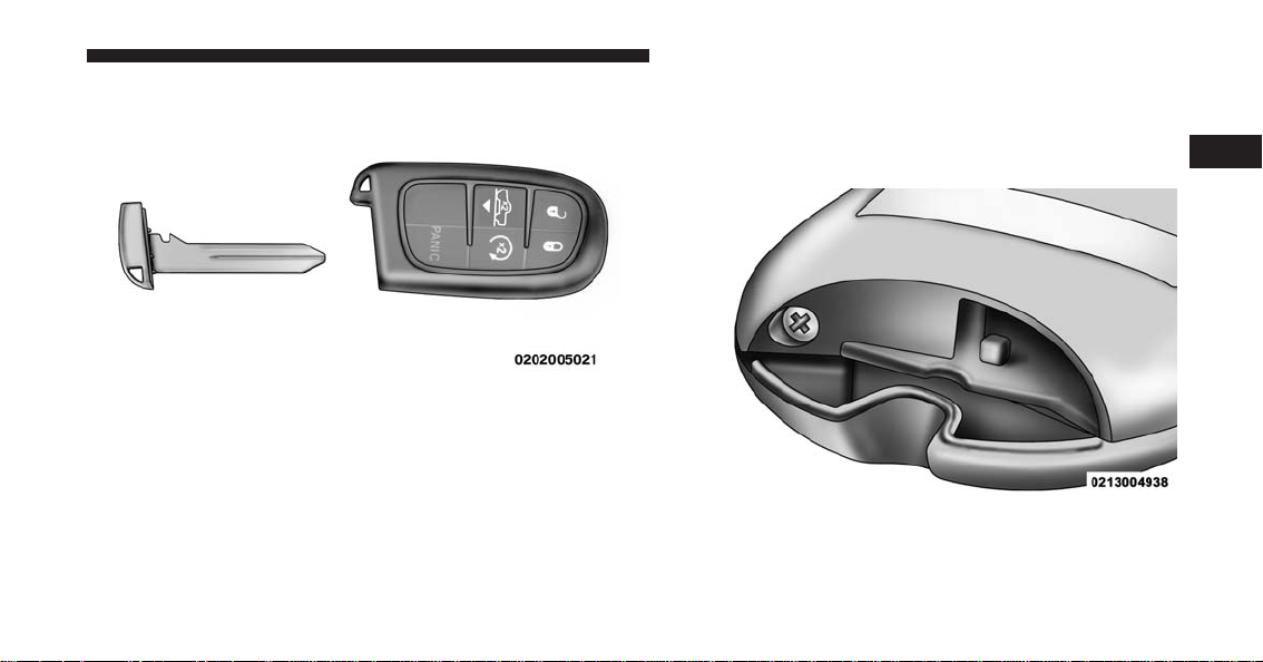
2. Separating RKE halves requires screw removal – if
equipped, and gently prying the two halves of the
RKE transmitter apart. Make sure not to damage the
seal during removal.
Emergency Key Removal
Remove Screw From Transmitter Case
2
THINGS TO KNOW BEFORE STARTING YOUR VEHICLE 31

3. Remove the battery by turning the back cover over
(battery facing downward) and tapping it lightly on a
solid surface such as a table or similar, then replace the
battery. When replacing the battery, match the + sign
on the battery to the + sign on the inside of the battery
clip, located on the back cover. Avoid touching the
Separating Transmitter Case Separating Transmitter Case
32 THINGS TO KNOW BEFORE STARTING YOUR VEHICLE

new battery with your fingers. Skin oils may cause
battery deterioration. If you touch a battery, clean it
with rubbing alcohol.
4. To assemble the RKE transmitter case, snap the two
halves together, reposition and secure the screw as
shown in step #2 for removal.
General Information
This device complies with Part 15 of the FCC rules and
RSS-210 of Industry Canada. Operation is subject to the
following conditions:
• This device may not cause harmful interference.
• This device must accept any interference received,
including interference that may cause undesired op-
eration.
NOTE: Changes or modifications not expressly approved
by the party responsible for compliance could void the
user’s authority to operate the equipment.
If your RKE transmitter fails to operate from a normal
distance, check for these two conditions:
1. A weak battery in the transmitter. The expected life of
the battery is a minimum of three years with normal
usage.
2. Closeness to a radio transmitter such as a radio station
tower, airport transmitter, and some mobile or CB
radios.
2
THINGS TO KNOW BEFORE STARTING YOUR VEHICLE 33

REMOTE STARTING SYSTEM — IF EQUIPPED
This system uses the Remote Keyless Entry
(RKE) transmitter to start the engine conve-
niently from outside the vehicle while still
maintaining security. The system has a range of
approximately 300 ft (91 m).
NOTE:
• The vehicle must be equipped with an automatic
transmission to be equipped with Remote Start.
• Obstructions between the vehicle and the RKE trans-
mitter may reduce this range.
How To Use Remote Start
All of the following conditions must be met before the
engine will remote start:
• Shift lever in PARK
• Doors closed
• Hood closed
• HAZARD switch off
• BRAKE switch inactive (brake pedal not pushed)
• Ignition key removed from ignition switch
• Battery at an acceptable charge level
• RKE PANIC button not pushed
• Fuel meets minimum requirement
• System not disabled from previous remote start event
• Vehicle security alarm not active
34 THINGS TO KNOW BEFORE STARTING YOUR VEHICLE
WARNING!
• Do not start or run an engine in a closed garage or
confined area. Exhaust gas contains Carbon Mon-
oxide (CO) which is odorless and colorless. Carbon
Monoxide is poisonous and can cause serious in-
jury or death when inhaled.
• Keep Remote Keyless Entry (RKE) transmitters
away from children. Operation of the Remote Start
System, windows, door locks or other controls
could cause serious injury or death.
Remote Start Abort Message
The following messages will display in the EVIC/DID if
the vehicle fails to remote start or exits remote start
prematurely:
• Remote Start Cancelled — Door Open
• Remote Start Cancelled — Hood Ajar
• Remote Start Cancelled — Fuel Low
• Remote Start Cancelled — System Fault
• Remote Start Disabled — Start Vehicle to Reset
The EVIC/DID message stays active until the ignition is
turned to the ON/RUN position.
To Enter Remote Start Mode
Push and release the REMOTE START button
on the RKE transmitter twice within five sec-
onds. The parking lights will flash, vehicle
doors will lock, and the horn will chirp twice (if
programmed). Once the vehicle has started, the engine
will run for 15 minutes.
2
THINGS TO KNOW BEFORE STARTING YOUR VEHICLE 35

NOTE:
• If your power door locks were unlocked, Remote Start
will automatically lock the doors.
• If an engine fault is present or fuel level is low, the
vehicle will start and then shut down in 10 seconds.
• The park lamps will turn on and remain on during
Remote Start mode.
• For security, power window and power sunroof op-
eration (if equipped) are disabled when the vehicle is
in the Remote Start mode.
• The engine can be started two consecutive times (two
15-minute cycles) with the RKE transmitter. However,
the ignition switch must be cycled to the ON/RUN
position before you can repeat the start sequence for a
third cycle.
To Exit Remote Start Mode Without Driving The
Vehicle
Push and release the REMOTE START button one time or
allow the engine to run for the entire 15-minute cycle.
NOTE: To avoid unintentional shut downs, the system
will disable the one time push of the REMOTE START
button for two seconds after receiving a valid Remote
Start request.
To Exit Remote Start Mode And Drive The Vehicle
Before the end of the 15-minute cycle, push and release
the UNLOCK button on the RKE transmitter to unlock
the doors and disarm the Vehicle Security Alarm System
(if equipped). Then, prior to the end of the 15-minute
cycle, cycle the ignition to the ON/RUN position.
Remote Start Comfort Systems — If Equipped
When Remote Start is activated, the heated steering
wheel and driver heated seat features will automatically
36 THINGS TO KNOW BEFORE STARTING YOUR VEHICLE

turn on in cold weather. In warm weather, the driver
vented seat feature will automatically turn on when the
remote start is activated. These features will stay on
through the duration of Remote Start or until the ignition
switch is turned to the ON/RUN position.
The Remote Start Comfort System can be activated and
deactivated through the Uconnect® System. Refer to
”Customer Programmable Features” in “Uconnect® Set-
tings” in “Understanding Your Instrument Panel” for
further information on Remote Start Comfort System
operation.
DOOR LOCKS
Manual Door Locks
Front and rear doors may be locked by moving the lock
knob down or unlocked by moving the lock knob up.
Front doors may be opened with the inside door handle
without lifting the lock knob.
Doors locked before closing will remain locked when
closed.
Door Lock Knob
2
THINGS TO KNOW BEFORE STARTING YOUR VEHICLE 37
The emergency key will unlock the driver door lock on
your vehicle.
WARNING!
• Do not leave children or animals inside parked
vehicles in hot weather. Interior heat build-up may
cause serious injury or death.
• For personal security and safety in the event of an
collision, lock the vehicle doors as you drive as
well as when you park and leave the vehicle.
• Before exiting a vehicle, always turn the vehicle
OFF, apply the parking brake, shift the automatic
transmission into PARK or the manual transmis-
sion into REVERSE,and push ignition button to
place ignition in OFF mode.
• Never leave children alone in a vehicle, or with
access to an unlocked vehicle.
(Continued)
WARNING! (Continued)
• Allowing children to be in a vehicle unattended is
dangerous for a number of reasons. A child or
others could be seriously or fatally injured. Chil-
dren should be warned not to touch the parking
brake, brake pedal or the gear selector.
• Do not leave the Key Fob in or near the vehicle, or
in a location accessible to children, and do not
leave the ignition of a vehicle equipped with
Keyless Enter-N-Go in the ACC or ON/RUN mode.
A child could operate power windows, other con-
trols, or move the vehicle.
Power Door Locks — If Equipped
A power door LOCK switch is on each front door trim
panel. Use this switch to lock or unlock the doors.
38 THINGS TO KNOW BEFORE STARTING YOUR VEHICLE

If you push the power door LOCK switch while the Key
Fob is in the ignition, and any front door is open, the
power locks will not operate. This prevents you from
accidentally locking your Key Fob in the vehicle. Remov-
ing the Key Fob or closing the door will allow the locks to
operate. A chime will sound if the Key Fob is in the
ignition switch and a door is open, as a reminder to
remove the Key Fob.
Automatic Door Locks — If Equipped
The auto door lock feature default condition is enabled.
When enabled, the door locks will lock automatically
when the vehicle’s speed exceeds 15 mph (24 km/h). The
auto door lock feature can be enabled or disabled by your
authorized dealer or through the Uconnect® Settings in
your radio.
Automatic Doors Unlock — If Equipped
This feature unlocks all of the doors of the vehicle when
either front door is opened. This will occur only after the
vehicle has been shifted into the PARK position after the
vehicle has been driven (shifted out of PARK and all
doors closed).
Power Door Lock Switch Location
2
THINGS TO KNOW BEFORE STARTING YOUR VEHICLE 39

Automatic Doors Unlock Programming — If
Equipped
The Automatic Doors Unlock feature can be enabled or
disabled as follows:
• For vehicles not equipped with a touchscreen radio,
refer to “Electronic Vehicle Information Center
(EVIC)/Settings (Customer-Programmable Features)”
in “Understanding Your Instrument Panel” for further
information.
• For vehicles equipped with a touchscreen radio, refer
to “Uconnect® Settings” in “Understanding Your In-
strument Panel” for further information.
NOTE: Use the Auto Unlock Doors feature in accordance
with local laws.
Child-Protection Door Lock
To provide a safer environment for children riding in the
rear seat, the rear doors (if equipped) of your vehicle
have the Child-Protection Door Lock system.
Child-Protection Door Lock Location
40 THINGS TO KNOW BEFORE STARTING YOUR VEHICLE
To use the system, open each rear door, use a flat blade
screwdriver (or emergency key) and rotate the dial to
engage and disengage the Child-Protection locks. When
the system on a door is engaged, that door can only be
opened by using the outside door handle even if the
inside door lock is in the unlocked position.
WARNING!
Avoid trapping anyone in a vehicle in a collision.
Remember that the rear doors can only be opened
from the outside when the Child-Protection locks are
engaged.
NOTE:
• After setting the Child-Protection Door Lock system,
always test the door from the inside to make certain it
is in the desired position.
• For emergency exit with the system engaged, move the
door lock switch to the UNLOCK position, roll down
the window and open the door with the outside door
handle.
Child Lock Control
2
THINGS TO KNOW BEFORE STARTING YOUR VEHICLE 41

KEYLESS ENTER-N-GO™
The Passive Entry system is an enhancement to the
vehicle’s Remote Keyless Entry (RKE) system and a
feature of Keyless Enter-N-Go™. Refer to “Keyless Enter-
N-Go™” in “Starting And Operating” for further infor-
mation. This feature allows you to lock and unlock the
vehicle’s door(s) without having to push the RKE trans-
mitter lock or unlock buttons.
NOTE:
• Passive Entry may be programmed ON/OFF. Refer to
“Uconnect® Settings” in “Understanding Your Instru-
ment Panel” for further information.
• If wearing gloves on your hands, or if it has been
raining on the Passive Entry door handle, the unlock
sensitivity can be affected, resulting in a slower re-
sponse time.
• If the vehicle is unlocked by the Passive Entry Door
Handle, and no door goes ajar within 60 seconds, the
vehicle will re-lock and if equipped will arm the
security alarm.
• The vehicles security alarm can be armed/disarmed
by pushing the passive entry key fob lock/unlock
buttons (if equipped).
To Unlock From The Driver’s Side:
With a valid Passive Entry RKE transmitter within 5 ft
(1.5 m) of the driver door handle, grab the front driver
door handle to unlock the driver’s door automatically.
The interior door panel lock knob will raise when the
door is unlocked.
42 THINGS TO KNOW BEFORE STARTING YOUR VEHICLE

NOTE: If “Unlock All Doors 1st Press” is programmed,
all doors will unlock when you grab hold of the front
driver’s door handle. To select between “Unlock Driver
Door 1st Press” and “Unlock All Doors 1st Press,” refer to
“Uconnect® Settings” in “Understanding Your Instru-
ment Panel” for further information.
To Unlock From The Passenger Side:
With a valid Passive Entry RKE transmitter within 5 ft
(1.5 m) of the passenger door handle, grab the front
passenger door handle to unlock all doors automatically.
The interior door panel lock knob will raise when the
door is unlocked.
NOTE: All doors will unlock when the front passenger
door handle is grabbed regardless of the driver’s door
unlock preference setting (“Unlock Driver Door 1st
Press” or “Unlock All Doors 1st Press”).
Preventing Inadvertent Locking Of Passive Entry RKE
Transmitter In Vehicle:
To minimize the possibility of unintentionally locking a
Passive Entry RKE transmitter inside your vehicle, the
Passive Entry system is equipped with an automatic door
unlock feature which will function if the ignition switch
is in the OFF position.
Grab The Door Handle To Unlock
2
THINGS TO KNOW BEFORE STARTING YOUR VEHICLE 43

If one of the vehicle doors is open and the door panel
switch is used to lock the vehicle, once all open doors
have been closed the vehicle checks the inside and
outside of the vehicle for any valid Passive Entry RKE
transmitters. If one of the vehicle’s Passive Entry RKE
transmitters is detected inside the vehicle, and no other
valid Passive Entry RKE transmitters are detected out-
side the vehicle, the Passive Entry System automatically
unlocks all vehicle doors and chirps the horn three times
(on the third attempt ALL doors will lock and the Passive
Entry RKE transmitter can be locked in the vehicle).
To Lock The Vehicle’s Doors:
With one of the vehicle’s Passive Entry RKE transmitters
within 5 ft (1.5 m) of the driver or passenger front door
handles, push the door handle LOCK button to lock all
doors.
Push The Door Handle Button To Lock
44 THINGS TO KNOW BEFORE STARTING YOUR VEHICLE

Do NOT grab the door handle when pushing the door
handle lock button. This could unlock the door(s).
NOTE:
• After pushing the door handle LOCK button, you
must wait two seconds before you can lock or unlock
the doors, using either Passive Entry door handle. This
is done to allow you to check if the vehicle is locked by
pulling the door handle, without the vehicle reacting
and unlocking.
• The Passive Entry system will not operate if the RKE
transmitter battery is dead.
The vehicle doors can also be locked by using the RKE
transmitter lock button or the lock button located on the
vehicle’s interior door panel.
Do NOT Grab The Door Handle When Locking
2
THINGS TO KNOW BEFORE STARTING YOUR VEHICLE 45
WINDOWS
Power Windows — If Equipped
The control on the left front door panel has UP-DOWN
switches that give you fingertip control of all power
windows. There is a single opening and closing switch on
the front passenger door for passenger window control
and on the rear doors of the Quad Cab and Crew Cab
models. The windows will operate when the ignition
switch is turned to the ON/RUN or ACC position, and
for up to 10 minutes after the ignition is turned OFF or
until a front door is opened.
NOTE: The Key Off Power Delay feature will allow the
power windows to operate for up to 10 minutes after the
ignition is turned OFF. This feature is cancelled when
either front door is opened.
WARNING!
Never leave children unattended in a vehicle. Do not
leave the Key Fob in or near the vehicle or in a
location accessible to children, and do not leave the
ignition of a vehicle equipped with Keyless Enter-
N-Go in the ACC or ON/RUN mode. Occupants,
(Continued)
Power Window Switches
46 THINGS TO KNOW BEFORE STARTING YOUR VEHICLE
WARNING! (Continued)
particularly unattended children, can become en-
trapped by the windows while operating the power
window switches. Such entrapment may result in
serious injury or death.
Auto-Down
Both the driver and front passenger window switch have
an Auto-Down feature. Push the window switch past the
first detent, release, and the window will go down
automatically. To cancel the Auto-Down movement, op-
erate the switch in either the up or down direction and
release the switch.
To stop the window from going all the way down during
the Auto-Down operation, pull up on the switch briefly.
To open the window part way, push to the first detent
and release it when you want the window to stop.
Auto-Up Feature With Anti-Pinch Protection
(4-Door Models Driver And Front Passenger Door
Only) — If Equipped
Lift the window switch fully upward to the second
detent, release, and the window will go up automatically.
To stop the window from going all the way up during the
Auto Up operation, push down on the switch briefly.
2
THINGS TO KNOW BEFORE STARTING YOUR VEHICLE 47
To close the window part way, lift the window switch to the
first detent and release when you want the window to stop.
NOTE: If the window runs into any obstacle during the
auto-closure, it will reverse direction and then go back
down. Remove the obstacle and use the window switch
again to close the window. Any impact due to rough road
conditions may trigger the auto reverse function unex-
pectedly during auto closure. If this happens, pull the
switch lightly to the first detent and hold to close the
window manually.
WARNING!
There is no anti-pinch protection when the window
is almost closed. Be sure to clear all objects from the
window before closing.
Reset Auto-Up
Should the Auto Up feature stop working, the window
may need to be reset. To reset Auto Up:
1. Make sure the door is fully closed.
2. Pull the window switch up to close the window
completely and continue to hold the switch up for an
additional two seconds after the window is closed.
3. Push the window switch down firmly to the second
detent to open the window completely and continue
to hold the switch down for an additional two seconds
after the window is fully open.
Window LOCKOUT Switch (4–Door Models Only)
The window LOCKOUT switch on the driver’s door
allows you to disable the window control on the rear
passenger doors. To disable the window controls on the
rear passenger doors, push the window LOCK button
into the latched or down position. To enable the window
48 THINGS TO KNOW BEFORE STARTING YOUR VEHICLE

controls, push the window LOCK button again and
return the switch to the released or up position.
Wind Buffeting
Wind buffeting can be described as the perception of
pressure on the ears or a helicopter-type sound in the
ears. Your vehicle may exhibit wind buffeting with the
windows down, or the sunroof (if equipped) in certain
open or partially open positions. This is a normal occur-
rence and can be minimized. If the buffeting occurs with
the rear windows open, then open the front and rear
windows together to minimize the buffeting. If the
buffeting occurs with the sunroof open, adjust the sun-
roof opening to minimize the buffeting.
OCCUPANT RESTRAINT SYSTEMS
Some of the most important safety features in your
vehicle are the restraint systems:
• Seat Belt Systems
• Supplemental Restraint Systems (SRS) Air Bags
• Child Restraints
Window Lockout Switch
2
THINGS TO KNOW BEFORE STARTING YOUR VEHICLE 49

Important Safety Precautions
Please pay close attention to the information in this
section. It tells you how to use your restraint system
properly, to keep you and your passengers as safe as
possible.
Here are some simple steps you can take to minimize the
risk of harm from a deploying air bag:
1. Children 12 years old and under should always ride
buckled up in a vehicle with a rear seat.
2. If a child from 2 to 12 years old (not in a rear-facing
child restraint) must ride in the front passenger seat,
move the seat as far back as possible and use the
proper child restraint. (Refer to “Child Restraints”)
3. Children that are not big enough to wear the vehicle
seat belt properly (Refer to ⬙Child Restraints⬙) should
be secured in a vehicle with a rear seat in child
restraints or belt-positioning booster seats. Older chil-
dren who do not use child restraints or belt-
positioning booster seats should ride properly buckled
up in a vehicle with a rear seat.
4. Never allow children to slide the shoulder belt behind
them or under their arm.
5. You should read the instructions provided with your
child restraint to make sure that you are using it
properly.
6. All occupants should always wear their lap and
shoulder belts properly.
7. The driver and front passenger seats should be moved
back as far as practical to allow the Advanced Front
Air Bags room to inflate.
50 THINGS TO KNOW BEFORE STARTING YOUR VEHICLE
8. Do not lean against the door or window. If your
vehicle has side air bags, and deployment occurs, the
side air bags will inflate forcefully into the space
between you and the door and you could be injured.
9. If the air bag system in this vehicle needs to be
modified to accommodate a disabled person, contact
the Customer Center. Phone numbers are provided
under ⬙If You Need Consumer Assistance.⬙
WARNING!
• Never place a rear-facing child restraint in front of
an air bag. A deploying passenger Advanced Front
Air Bag can cause death or serious injury to a child
12 years or younger, including a child in a rear-
facing child restraint.
• Only use a rear-facing child restraint in a vehicle
with a rear seat.
Seat Belt Systems
Buckle up even though you are an excellent driver, even
on short trips. Someone on the road may be a poor driver
and could cause a collision that includes you. This can
happen far away from home or on your own street.
Research has shown that seat belts save lives, and they
can reduce the seriousness of injuries in a collision. Some
of the worst injuries happen when people are thrown
from the vehicle. Seat belts reduce the possibility of
ejection and the risk of injury caused by striking the
inside of the vehicle. Everyone in a motor vehicle should
be belted at all times.
Enhanced Seat Belt Use Reminder System
(BeltAlert)
BeltAlert is a feature intended to remind the driver
and outboard front passenger (if equipped with out-
board front passenger BeltAlert) to buckle their seat
belts. The feature is active whenever the ignition
2
THINGS TO KNOW BEFORE STARTING YOUR VEHICLE 51

switch is in the START or ON/RUN position. If the
driver or outboard front seat passenger is unbelted,
the Seat Belt Reminder Light will turn on and remain
on until both outboard front seat belts are buckled.
The BeltAlert warning sequence begins after the vehicle
speed is over 5 mph (8 km/h) by blinking the Seat Belt
Reminder Light and sounding an intermittent chime.
Once the sequence starts, it will continue for the entire
duration or until the respective seat belts are buckled.
After the sequence completes, the Seat Belt Reminder
Light remains illuminated until the respective seat belts
are buckled. The driver should instruct all other occu-
pants to buckle their seat belts. If an outboard front seat
belt is unbuckled while traveling at speeds greater than
5 mph (8 km/h), BeltAlert will provide both audio and
visual notification.
The outboard front passenger seat BeltAlert is not active
when the outboard front passenger seat is unoccupied.
BeltAlert may be triggered when an animal or heavy
object is on the outboard front passenger seat or when the
seat is folded flat (if equipped). It is recommended that
pets be restrained in the rear seat (if equipped) in pet
harnesses or pet carriers that are secured by seat belts,
and cargo is properly stowed.
BeltAlert can be activated or deactivated by your autho-
rized dealer. FCA US LLC does not recommend deacti-
vating BeltAlert.
NOTE: If BeltAlert has been deactivated, the Seat Belt
Reminder Light will continue to illuminate while the
driver’s or outboard front passenger’s (if equipped with
BeltAlert) seat belt remains unbuckled.
Lap/Shoulder Belts
All seating positions except the Quad Cab®, Mega Cab®
and Crew Cab front center seating position have combi-
nation lap/shoulder belts.
52 THINGS TO KNOW BEFORE STARTING YOUR VEHICLE
The seat belt webbing retractor will lock only during very
sudden stops or collisions. This feature allows the shoul-
der part of the seat belt to move freely with you under
normal conditions. However, in a collision the seat belt
will lock and reduce your risk of striking the inside of the
vehicle or being thrown out of the vehicle.
WARNING!
• Relying on the air bags alone could lead to more
severe injuries in a collision. The air bags work
with your seat belt to restrain you properly. In
some collisions, the air bags won’t deploy at all.
Always wear your seat belt even though you have
air bags.
• In a collision, you and your passengers can suffer
much greater injuries if you are not properly buck-
led up. You can strike the interior of your vehicle or
(Continued)
WARNING! (Continued)
other passengers, or you can be thrown out of the
vehicle. Always be sure you and others in your
vehicle are buckled up properly.
• It is dangerous to ride in a cargo area, inside or
outside of a vehicle. In a collision, people riding in
these areas are more likely to be seriously injured
or killed.
• Do not allow people to ride in any area of your
vehicle that is not equipped with seats and seat
belts.
• Be sure everyone in your vehicle is in a seat and
using a seat belt properly.
• Wearing your seat belt incorrectly could make your
injuries in a collision much worse. You might
suffer internal injuries, or you could even slide out
of the seat belt. Follow these instructions to wear
(Continued)
2
THINGS TO KNOW BEFORE STARTING YOUR VEHICLE 53
WARNING! (Continued)
your seat belt safely and to keep your passengers
safe, too.
• Two people should never be belted into a single
seat belt. People belted together can crash into one
another in a collision, hurting one another badly.
Never use a lap/shoulder belt or a lap belt for more
than one person, no matter what their size.
• A lap belt worn too high can increase the risk of
injury in a collision. The seat belt forces won’t be at
the strong hip and pelvic bones, but across your
abdomen. Always wear the lap part of your seat
belt as low as possible and keep it snug.
• A twisted seat belt may not protect you properly. In
a collision, it could even cut into you. Be sure the
seat belt is flat against your body, without twists. If
you can’t straighten a seat belt in your vehicle, take
(Continued)
WARNING! (Continued)
it to your authorized dealer immediately and have
it fixed.
• A seat belt that is buckled into the wrong buckle
will not protect you properly. The lap portion could
ride too high on your body, possibly causing inter-
nal injuries. Always buckle your seat belt into the
buckle nearest you.
• A seat belt that is too loose will not protect you
properly. In a sudden stop, you could move too far
forward, increasing the possibility of injury. Wear
your seat belt snugly.
• A seat belt that is worn under your arm is danger-
ous. Your body could strike the inside surfaces of
the vehicle in a collision, increasing head and neck
injury. A seat belt worn under the arm can cause
internal injuries. Ribs aren’t as strong as shoulder
(Continued)
54 THINGS TO KNOW BEFORE STARTING YOUR VEHICLE
WARNING! (Continued)
bones. Wear the seat belt over your shoulder so that
your strongest bones will take the force in a colli-
sion.
• A shoulder belt placed behind you will not protect
you from injury during a collision. You are more
likely to hit your head in a collision if you do not
wear your shoulder belt. The lap and shoulder belt
are meant to be used together.
• A frayed or torn seat belt could rip apart in a
collision and leave you with no protection. Inspect
the seat belt system periodically, checking for cuts,
frays, or loose parts. Damaged parts must be re-
placed immediately. Do not disassemble or modify
the seat belt system. Seat belt assemblies must be
replaced after a collision.
Lap/Shoulder Belt Operating Instructions
1. Enter the vehicle and close the door. Sit back and
adjust the seat.
2. The seat belt latch plate is above the back of the front
seat, and next to your arm in the rear seat (for vehicles
equipped with a rear seat). Grasp the latch plate and
pull out the seat belt. Slide the latch plate up the
webbing as far as necessary to allow the seat belt to go
around your lap.
2
THINGS TO KNOW BEFORE STARTING YOUR VEHICLE 55

3. When the seat belt is long enough to fit, insert the latch
plate into the buckle until you hear a “click.”
Pulling Out The Latch Plate
Inserting Latch Plate Into Buckle
56 THINGS TO KNOW BEFORE STARTING YOUR VEHICLE

4. Position the lap belt so that it is snug and lies low
across your hips, below your abdomen. To remove
slack in the lap belt portion, pull up on the shoulder
belt. To loosen the lap belt if it is too tight, tilt the latch
plate and pull on the lap belt. A snug seat belt reduces
the risk of sliding under the seat belt in a collision.
5. Position the shoulder belt across the shoulder and
chest with minimal, if any slack so that it is comfort-
able and not resting on your neck. The retractor will
withdraw any slack in the shoulder belt.
6. To release the seat belt, push the red button on the
buckle. The seat belt will automatically retract to its
stowed position. If necessary, slide the latch plate
down the webbing to allow the seat belt to retract
fully.
First Row Center Seat Belt Operating Instructions
(Regular Cab Only)
The first row center seat belt features a seat belt with a
mini-latch and mini-buckle, which allows the seat belt to
detach from the lower anchor when the seat is folded.
The mini-buckle and seat belt can then be stored out of
the way in the seat for added convenience.
Positioning The Lap Belt
2
THINGS TO KNOW BEFORE STARTING YOUR VEHICLE 57

1. Remove the mini-latch and regular latch from its
stowed position on the seat.
Detaching Buckle With Seat Belt Tongue
Inserting Latch Plate
58 THINGS TO KNOW BEFORE STARTING YOUR VEHICLE

2. Grasp the mini-latch plate and pull the seat belt over
the seat.
3. Route the shoulder belt to the inside of the [right/ left]
head restraint.
4. When the seat belt is long enough to fit, insert the
mini-latch plate into the mini-buckle until you hear a
“click.”
5. Sit back in seat. Slide the regular latch plate up the
webbing as far as necessary to allow the seat belt to go
around your lap.
6. When the seat belt is long enough to fit, insert the latch
plate into the buckle until you hear a “click.”
7. Position the lap belt so that it is snug and lies low
across your hips, below your abdomen. To remove
slack in the lap belt portion, pull up on the shoulder
belt. To loosen the lap belt if it is too tight, pull on the
lap belt. A snug seat belt reduces the risk of sliding
under the seat belt in a collision.
8. Position the shoulder belt on your chest so that it is
comfortable and not resting on your neck. The retrac-
tor will withdraw any slack in the seat belt.
In Use Position
2
THINGS TO KNOW BEFORE STARTING YOUR VEHICLE 59
9. To release the seat belt, push the red button on the
buckle.
10. To disengage the mini-latch from the mini-buckle for
storage, insert the regular latch plate into the center
red slot on the mini-buckle. The seat belt will auto-
matically retract to its stowed position. If necessary,
slide the latch plate down the webbing to allow the
seat belt to retract fully. Insert the mini-latch plate
and regular latch plate into its stowed position.
WARNING!
• If the mini-latch and mini-buckle are not properly
connected when the seat belt is used by an occu-
pant, the seat belt will not be able to provide
proper restraint and will increase the risk of injury
in a collision.
(Continued)
WARNING! (Continued)
• When reattaching the mini-latch and mini-buckle,
ensure the seat belt webbing is not twisted. If the
webbing is twisted, follow the preceding proce-
dure to detach the mini-latch and mini-buckle,
untwist the webbing, and reattach the mini-latch
and mini-buckle.
Lap/Shoulder Belt Untwisting Procedure
Use the following procedure to untwist a twisted lap/
shoulder belt.
1. Position the latch plate as close as possible to the
anchor point.
2.
At about 6 to 12 inches (15 to 30 cm) above the latch plate,
grasp and twist the seat belt webbing 180 degrees to
create a fold that begins immediately above the latch
plate.
60 THINGS TO KNOW BEFORE STARTING YOUR VEHICLE

3. Slide the latch plate upward over the folded webbing.
The folded webbing must enter the slot at the top of
the latch plate.
4. Continue to slide the latch plate up until it clears the
folded webbing and the seat belt is no longer twisted.
Adjustable Upper Shoulder Belt Anchorage
In the driver and front passenger seats, the top of the
shoulder belt can be adjusted upward or downward to
position the seat belt away from your neck. Push or
squeeze the anchorage button to release the anchorage,
and move it up or down to the position that serves you
best.
As a guide, if you are shorter than average, you will
prefer the shoulder belt anchorage in a lower position,
and if you are taller than average, you will prefer the
shoulder belt anchorage in a higher position. After you
release the anchorage button, try to move it up or down
to make sure that it is locked in position.
Adjustable Anchorage
2
THINGS TO KNOW BEFORE STARTING YOUR VEHICLE 61
NOTE: The adjustable upper shoulder belt anchorage is
equipped with an Easy Up feature. This feature allows
the shoulder belt anchorage to be adjusted in the upward
position without pushing or squeezing the release but-
ton. To verify the shoulder belt anchorage is latched, pull
downward on the shoulder belt anchorage until it is
locked into position.
Seat Belt Extender
If a seat belt is not long enough to fit properly, even when
the webbing is fully extended and the adjustable upper
shoulder belt anchorage (if equipped) is in its lowest
position, your authorized dealer can provide you with a
Seat Belt Extender. The Seat Belt Extender should be used
only if the existing seat belt is not long enough. When the
Seat Belt Extender is not required for a different occu-
pant, it must be removed.
WARNING!
• ONLY use a Seat Belt Extender if it is physically
required in order to properly fit the original seat
belt system. DO NOT USE the Seat Belt Extender
if, when worn, the distance between the front edge
of the Seat Belt Extender buckle and the center of
the occupant’s body is LESS than 6 inches.
• Using a Seat Belt Extender when not needed can
increase the risk of serious injury or death in a
collision. Only use the Seat Belt Extender when the
lap belt is not long enough and only use in the
recommended seating positions. Remove and store
the Seat Belt Extender when not needed.
Seat Belts And Pregnant Women
We recommend that pregnant women use the seat belts
throughout their pregnancy. Keeping the mother safe is
the best way to keep the baby safe.
62 THINGS TO KNOW BEFORE STARTING YOUR VEHICLE

Pregnant women should wear the lap part of the seat belt
across the thighs and as snug across the hips as possible.
Keep the seat belt low so that it does not come across the
abdomen. That way the strong bones of the hips will take
the force if there is a collision.
Seat Belt Pretensioner
The front seat belt system is equipped with pretensioning
devices that are designed to remove slack from the seat
belt in the event of a collision. These devices may
improve the performance of the seat belt by removing
slack from the seat belt early in a collision. Pretensioners
work for all size occupants, including those in child
restraints.
NOTE: These devices are not a substitute for proper seat
belt placement by the occupant. The seat belt still must be
worn snugly and positioned properly.
The pretensioners are triggered by the Occupant Re-
straint Controller (ORC). Like the air bags, the preten-
sioners are single use items. A deployed pretensioner or
a deployed air bag must be replaced immediately.
Energy Management Feature — If Equipped
This vehicle has a seat belt system with an Energy
Management feature in the front seating positions that
may help further reduce the risk of injury in the event of
a collision. This seat belt system has a retractor assembly
that is designed to release webbing in a controlled
manner.
Front Center Lap Belts
The front center seating position for the Quad Cab®,
Mega Cab® and Crew Cab has a lap belt only. To buckle
the lap belt, slide the latch plate into the buckle until you
hear a ⬙click.⬙ To lengthen the lap belt, tilt the latch plate
and pull.
2
THINGS TO KNOW BEFORE STARTING YOUR VEHICLE 63

To remove slack, pull the loose end of the webbing. Wear
the lap belt snug against the hips. Sit back and upright in
the seat, then adjust the seat belt as tightly as is comfort-
able.
Automatic Locking Retractors (ALR) – If Equipped
The seat belts in the passenger seating positions may be
equipped with a Switchable Automatic Locking Retractor
(ALR) which is used to secure a child restraint system.
For additional information, refer to “Installing Child
Restraints Using The Vehicle Seat Belt” under the “Child
Restraints” section of this manual. The table below
defines the type of feature for each seating position.
Regular Cab
64 THINGS TO KNOW BEFORE STARTING YOUR VEHICLE
If the passenger seating position is equipped with an
ALR and is being used for normal usage, only pull the
seat belt webbing out far enough to comfortably wrap
around the occupant’s mid-section so as to not activate
the ALR. If the ALR is activated, you will hear a clicking
sound as the seat belt retracts. Allow the webbing to
retract completely in this case and then carefully pull out
only the amount of webbing necessary to comfortably
wrap around the occupant’s mid-section. Slide the latch
plate into the buckle until you hear a ⬙click.⬙
In Automatic Locking Mode, the shoulder belt is auto-
matically pre-locked. The seat belt will still retract to
remove any slack in the shoulder belt. Use the Automatic
Locking Mode anytime a child restraint is installed in a
seating position that has a seat belt with this feature.
Children 12 years old and under should always be
properly restrained in a vehicle with a rear seat.
WARNING!
• Never place a rear-facing child restraint in front of
an air bag. A deploying Passenger Advanced Front
Air Bag can cause death or serious injury to a child
(Continued)
Quad Cab®/Mega Cab®/Crew Cab
• ALR = Switchable Automatic Locking Retractor
2
THINGS TO KNOW BEFORE STARTING YOUR VEHICLE 65
WARNING! (Continued)
12 years or younger, including a child in a rear-
facing child restraint.
• Only use a rear-facing child restraint in a vehicle
with a rear seat.
How To Engage The Automatic Locking Mode
1. Buckle the combination lap and shoulder belt.
2. Grasp the shoulder portion and pull downward until
the entire seat belt is extracted.
3. Allow the seat belt to retract. As the seat belt retracts,
you will hear a clicking sound. This indicates the seat
belt is now in the Automatic Locking Mode.
How To Disengage The Automatic Locking Mode
Unbuckle the combination lap/shoulder belt and allow it
to retract completely to disengage the Automatic Locking
Mode and activate the vehicle sensitive (emergency)
locking mode.
WARNING!
• The seat belt assembly must be replaced if the
switchable Automatic Locking Retractor (ALR) fea-
ture or any other seat belt function is not working
properly when checked according to the proce-
dures in the Service Manual.
• Failure to replace the seat belt assembly could
increase the risk of injury in collisions.
• Do not use the Automatic Locking Mode to restrain
occupants who are wearing the seat belt or children
who are using booster seats. The locked mode is
only used to install rear-facing or forward-facing
child restraints that have a harness for restraining
the child.
66 THINGS TO KNOW BEFORE STARTING YOUR VEHICLE

Supplemental Restraint System (SRS)
Air Bag System Components
Your vehicle may be equipped with the following air bag
system components:
• Occupant Restraint Controller (ORC)
• Air Bag Warning Light
• Steering Wheel and Column
• Instrument Panel
• Knee Impact Bolsters
• Advanced Front Air Bags
• Supplemental Side Air Bags
• Front And Side Impact Sensors — If Equipped
• Seat Belt Pretenioners
• Seat Belt Buckle Switch
Advanced Front Air Bags
This vehicle has Advanced Front Air Bags for both the
driver and front passenger as a supplement to the seat
belt restraint systems. The driver’s Advanced Front Air
Bag is mounted in the center of the steering wheel. The
passenger’s Advanced Front Air Bag is mounted in the
instrument panel, above the glove compartment. The
words “SRS AIRBAG” or “AIRBAG” are embossed on
the air bag covers.
2
THINGS TO KNOW BEFORE STARTING YOUR VEHICLE 67
WARNING!
• Being too close to the steering wheel or instrument
panel during Advanced Front Air Bag deployment
could cause serious injury, including death. Air
bags need room to inflate. Sit back, comfortably
extending your arms to reach the steering wheel or
instrument panel.
• Never place a rear-facing child restraint in front of
an air bag. A deploying Passenger Advanced Front
Air Bag can cause death or serious injury to a child
12 years or younger, including a child in a rear-
facing child restraint.
• Only use a rear-facing child restraint in a vehicle
with a rear seat.
Advanced Front Air Bag And Knee Bolster Locations
1 — Driver And Passenger Advanced Front Air Bags
2 — Driver/Passenger Knee Impact Bolsters
68 THINGS TO KNOW BEFORE STARTING YOUR VEHICLE
Advanced Front Air Bag Features
The Advanced Front Air Bag system has multistage
driver and front passenger air bags. This system provides
output appropriate to the severity and type of collision as
determined by the Occupant Restraint Controller (ORC),
which may receive information from the front impact
sensors (if equipped) or other system components.
The first stage inflator is triggered immediately during an
impact that requires air bag deployment. A low energy
output is used in less severe collisions. A higher energy
output is used for more severe collisions.
This vehicle may be equipped with a driver and/or front
passenger seat belt buckle switch that detects whether
the driver or front passenger seat belt is buckled. The seat
belt buckle switch may adjust the inflation rate of the
Advanced Front Air Bags.
WARNING!
• No objects should be placed over or near the air
bag on the instrument panel or steering wheel,
because any such objects could cause harm if the
vehicle is in a collision severe enough to cause the
air bags to inflate.
• Do not put anything on or around the air bag
covers or attempt to open them manually. You may
damage the air bags and you could be injured
because the air bags may no longer be functional.
The protective covers for the air bag cushions are
designed to open only when the air bags are
inflating.
• Relying on the air bags alone could lead to more
severe injuries in a collision. The air bags work
with your seat belt to restrain you properly. In
(Continued)
2
THINGS TO KNOW BEFORE STARTING YOUR VEHICLE 69
WARNING! (Continued)
some collisions, air bags won’t deploy at all. Al-
ways wear your seat belts even though you have air
bags.
Advanced Front Air Bag Operation
Advanced Front Air Bags are designed to provide addi-
tional protection by supplementing the seat belts. Ad-
vanced Front Air Bags are not expected to reduce the risk
of injury in rear, side, or rollover collisions. The Ad-
vanced Front Air Bags will not deploy in all frontal
collisions, including some that may produce substantial
vehicle damage — for example, some pole collisions,
truck underrides, and angle offset collisions.
On the other hand, depending on the type and location of
impact, Advanced Front Air Bags may deploy in crashes
with little vehicle front-end damage but that produce a
severe initial deceleration.
Because air bag sensors measure vehicle deceleration
over time, vehicle speed and damage by themselves are
not good indicators of whether or not an air bag should
have deployed.
Seat belts are necessary for your protection in all colli-
sions, and also are needed to help keep you in position,
away from an inflating air bag.
When the ORC detects a collision requiring the Ad-
vanced Front Air Bags, it signals the inflator units. A large
quantity of non-toxic gas is generated to inflate the
Advanced Front Air Bags.
The steering wheel hub trim cover and the upper right
side of the instrument panel separate and fold out of the
way as the air bags inflate to their full size. The Advanced
Front Air Bags fully inflate in less time than it takes to
blink your eyes. The air bags then quickly deflate while
helping to restrain the driver and front passenger.
70 THINGS TO KNOW BEFORE STARTING YOUR VEHICLE
Knee Impact Bolsters
The Knee Impact Bolsters help protect the knees of the
driver and front passenger, and position the front occu-
pants for improved interaction with the Advanced Front
Air Bags.
WARNING!
• Do not drill, cut, or tamper with the knee impact
bolsters in any way.
• Do not mount any accessories to the knee impact
bolsters such as alarm lights, stereos, citizen band
radios, etc.
Supplemental Side Air Bags
Your vehicle is equipped with two types of side air bags:
1. Supplemental Seat-Mounted Side Air Bags (SABs):
Located in the outboard side of the front seats. The
SABs are marked with a “SRS AIRBAG” or “AIRBAG”
label sewn into the outboard side of the seats.
The SABs may help to reduce the risk of occupant injury
during certain side impact and certain rollover events, in
addition to the injury reduction potential provided by the
seat belts and body structure.
Front Supplemental Seat-Mounted Side Air Bag Label
2
THINGS TO KNOW BEFORE STARTING YOUR VEHICLE 71
When the SAB deploys, it opens the seam on the out-
board side of the seatback’s trim cover. The inflating SAB
deploys through the seat seam into the space between the
occupant and the door. The SAB moves at a very high
speed and with such a high force that it could injure you
if you are not seated properly, or if items are positioned
in the area where the SAB inflates. Children are at an
even greater risk of injury from a deploying air bag.
WARNING!
Do not use accessory seat covers or place objects
between you and the Side Air Bags; the performance
could be adversely affected and/or objects could be
pushed into you, causing serious injury.
2. Supplemental Side Air Bag Inflatable Curtains
(SABICs): Located above the side windows. The trim
covering the SABICs is labeled “SRS AIRBAG” or
“AIRBAG.”
SABICs may help reduce the risk of head injury to front
and rear seat outboard occupants. SABICs may reduce
the risk of injuries in certain side impact and vehicle
Supplemental Side Air Bag Inflatable Curtain (SABIC)
Label Location
72 THINGS TO KNOW BEFORE STARTING YOUR VEHICLE
rollover events, in addition to the injury reduction poten-
tial provided by the seat belts and body structure.
The SABICs deploy downward, covering the side win-
dows. An inflating SABIC pushes the outside edge of the
trim out of the way and covers the window. The SABICs
inflate with enough force to injure you if you are not
belted and seated properly, or if items are positioned in
the area where the SABICs inflate. Children are at an
even greater risk of injury from a deploying air bag.
The SABICs may help reduce the risk of partial or
complete ejection of vehicle occupants through side
windows in certain rollover or side impact events.
WARNING!
•
Your vehicle is equipped with left and right
Supplemental Side Air Bag Inflatable Curtains
(SABICs). Do not stack luggage or other cargo up
high enough to block the deployment of the
SABICs. The trim covering above the side win-
dows where the SABIC and its deployment path
are located should remain free from any obstruc-
tions.
• Your vehicle is equipped with SABICs. In order for
the SABICs to work as intended, do not install any
accessory items in your vehicle which could alter
the roof. Do not add an aftermarket sunroof to your
vehicle. Do not add roof racks that require perma-
nent attachments (bolts or screws) for installation
on the vehicle roof. Do not drill into the roof of the
vehicle for any reason.
2
THINGS TO KNOW BEFORE STARTING YOUR VEHICLE 73
The SABICs and SABs (“Side Air Bags”) are designed to
activate in certain side impacts and certain rollover
events. The Occupant Restraint Controller (“ORC”) de-
termines whether the deployment of the Side Air Bags in
a particular side impact or rollover event is appropriate,
based on the severity and type of collision. Vehicle
damage by itself is not a good indicator of whether or not
Side Air Bags should have deployed.
Side Air Bags are a supplement to the seat belt restraint
system. Side Air Bags deploy in less time than it takes to
blink your eyes. Occupants, including children, who are
up against or very close to Side Air Bags can be seriously
injured or killed. Occupants, including children, should
never lean on or sleep against the door, side windows, or
area where the Side Air Bags inflate, even if they are in an
infant or child restraint.
Seat belts (and child restraints where appropriate) are
necessary for your protection in all collisions. They also
help keep you in position, away from inflating Side Air
Bags. To get the best protection from the Side Air Bags,
occupants must wear their seat belts properly and sit
upright with their backs against the seats. Children must
be properly restrained in a child restraint or booster seat
that is appropriate for the size of the child.
WARNING!
• Side Air Bags need room to inflate. Do not lean
against the door or window. Sit upright in the
center of the seat.
• Being too close to the Side Air Bags during deploy-
ment could cause you to be severely injured or
killed.
• Relying on the Side Air Bags alone could lead to
more severe injuries in a collision. The Side Air
Bags work with your seat belt to restrain you
(Continued)
74 THINGS TO KNOW BEFORE STARTING YOUR VEHICLE
WARNING! (Continued)
properly. In some collisions, Side Air Bags won’t
deploy at all. Always wear your seat belt even
though you have Side Air Bags.
NOTE: Air bag covers may not be obvious in the interior
trim, but they will open during air bag deployment.
Side Impacts
In side impacts, the side impact sensors aid the ORC in
determining the appropriate response to impact events.
The system is calibrated to deploy the Side Air Bags on
the impact side of the vehicle during impacts that require
Side Air Bag occupant protection. In side impacts, the
Side Air Bags deploy independently; a left side impact
deploys the left Side Air Bags only and a right side
impact deploys the right Side Air Bags only.
The Side Air Bags will not deploy in all side collisions,
including some collisions at certain angles, or some side
collisions that do not impact the area of the passenger
compartment. The Side Air Bags may deploy during
angled or offset frontal collisions where the Advanced
Front Air Bags deploy.
Rollover Events
Side Air Bags are designed to activate in certain rollover
events. The ORC determines whether the deployment of
the Side Air Bags in a particular rollover event is appro-
priate, based on the severity and type of collision. Vehicle
damage by itself is not a good indicator of whether or not
Side Air Bags should have deployed.
The Side Air Bags will not deploy in all rollover events.
The rollover sensing-system determines if a rollover
event may be in progress and whether deployment is
appropriate. A slower-developing event may deploy the
seat belt pretensioners on both sides of the vehicle. A
2
THINGS TO KNOW BEFORE STARTING YOUR VEHICLE 75

faster-developing event may deploy the seat belt preten-
sioners as well as the SABs and SABICs on both sides of
the vehicle. The rollover sensing-system may also deploy
the seat belt pretensioners, with or without the SABs and
SABICs, on both sides of the vehicle if the vehicle
experiences a near rollover event.
If A Deployment Occurs
The Advanced Front Air Bags are designed to deflate
immediately after deployment.
NOTE: Front and/or side air bags will not deploy in all
collisions. This does not mean something is wrong with
the air bag system.
If you do have a collision which deploys the air bags, any
or all of the following may occur:
• The air bag material may sometimes cause abrasions
and/or skin reddening to the occupants as the air bags
deploy and unfold. The abrasions are similar to fric-
tion rope burns or those you might get sliding along a
carpet or gymnasium floor. They are not caused by
contact with chemicals. They are not permanent and
normally heal quickly. However, if you haven’t healed
significantly within a few days, or if you have any
blistering, see your doctor immediately.
• As the air bags deflate, you may see some smoke-like
particles. The particles are a normal by-product of the
process that generates the non-toxic gas used for air
bag inflation. These airborne particles may irritate the
skin, eyes, nose, or throat. If you have skin or eye
irritation, rinse the area with cool water. For nose or
throat irritation, move to fresh air. If the irritation
continues, see your doctor. If these particles settle on
your clothing, follow the garment manufacturer’s in-
structions for cleaning.
76 THINGS TO KNOW BEFORE STARTING YOUR VEHICLE
Do not drive your vehicle after the air bags have de-
ployed. If you are involved in another collision, the air
bags will not be in place to protect you.
WARNING!
Deployed air bags and seat belt pretensioners cannot
protect you in another collision. Have the air bags,
seat belt pretensioners, and the seat belt retractor
assemblies replaced by an authorized dealer imme-
diately. Also, have the Occupant Restraint Controller
System serviced as well.
NOTE:
• Air bag covers may not be obvious in the interior trim,
but they will open during air bag deployment.
• After any collision, the vehicle should be taken to an
authorized dealer immediately.
Enhanced Accident Response System
In the event of an impact, if the communication network
remains intact, and the power remains intact, depending
on the nature of the event, the ORC will determine
whether to have the Enhanced Accident Response Sys-
tem perform the following functions:
• Cut off fuel to the engine.
• Flash hazard lights as long as the battery has power or
until the ignition switch is turned to the “OFF” posi-
tion.
• Turn on the interior lights, which remain on as long as
the battery has power or until the ignition switch is
turned to the “OFF” position.
• Unlock the doors automatically.
2
THINGS TO KNOW BEFORE STARTING YOUR VEHICLE 77

System Reset Procedure
In order to reset the Enhanced Accident Response System
functions after an event, the ignition switch must be
changed from ignition START or ON/RUN to ignition
OFF.
Air Bag Warning Light
The air bags must be ready to inflate for your
protection in a collision. The Occupant Re-
straint Controller (ORC) monitors the internal
circuits and interconnecting wiring associated
with air bag system electrical components.
The ORC monitors the readiness of the electronic parts of
the air bag system whenever the ignition switch is in the
START or ON/RUN position. If the ignition switch is in
the OFF position or in the ACC position, the air bag
system is not on and the air bags will not inflate.
The ORC contains a backup power supply system that
may deploy the air bags even if the battery loses power or
it becomes disconnected prior to deployment.
The ORC turns on the Air Bag Warning Light in the
instrument panel for approximately four to eight seconds
for a self-check when the ignition switch is first turned to
the ON/RUN position. After the self-check, the Air Bag
Warning Light will turn off. If the ORC detects a mal-
function in any part of the system, it turns on the Air Bag
Warning Light, either momentarily or continuously. A
single chime will sound to alert you if the light comes on
again after initial startup.
The ORC also includes diagnostics that will illuminate
the instrument panel Air Bag Warning Light if a malfunc-
tion is detected that could affect the air bag system. The
diagnostics also record the nature of the malfunction.
While the air bag system is designed to be maintenance
78 THINGS TO KNOW BEFORE STARTING YOUR VEHICLE

free, if any of the following occurs, have an authorized
dealer service the air bag system immediately.
• The Air Bag Warning Light does not come on during
the four to eight seconds when the ignition switch is
first turned to the ON/RUN position.
• The Air Bag Warning Light remains on after the four to
eight-second interval.
• The Air Bag Warning Light comes on intermittently or
remains on while driving.
NOTE: If the speedometer, tachometer, or any engine
related gauges are not working, the Occupant Restraint
Controller (ORC) may also be disabled. In this condition
the air bags may not be ready to inflate for your protec-
tion. Have an authorized dealer service the air bag
system immediately.
WARNING!
Ignoring the Air Bag Warning Light in your instru-
ment panel could mean you won’t have the air bags
to protect you in a collision. If the light does not come
on as a bulb check when the ignition is first placed in
the on position, and stays on after you start the
vehicle, or if it comes on as you drive, have an
authorized dealer service the air bag system immedi-
ately.
2
THINGS TO KNOW BEFORE STARTING YOUR VEHICLE 79
Maintaining Your Air Bag System
WARNING!
• Modifications to any part of the air bag system
could cause it to fail when you need it. You could
be injured if the air bag system is not there to
protect you. Do not modify the components or
wiring, including adding any kind of badges or
stickers to the steering wheel hub trim cover or the
upper right side of the instrument panel. Do not
modify the front bumper, vehicle body structure, or
add aftermarket side steps or running boards.
• It is dangerous to try to repair any part of the air
bag system yourself. Be sure to tell anyone who
works on your vehicle that it has an air bag system.
• Do not attempt to modify any part of your air bag
system. The air bag may inflate accidentally or may
(Continued)
WARNING! (Continued)
not function properly if modifications are made.
Take your vehicle to an authorized dealer for any
air bag system service. If your seat, including your
trim cover and cushion, needs to be serviced in any
way (including removal or loosening/tightening of
seat attachment bolts), take the vehicle to your
authorized dealer. Only manufacturer approved
seat accessories may be used. If it is necessary to
modify the air bag system for persons with dis-
abilities, contact your authorized dealer.
Event Data Recorder (EDR)
This vehicle is equipped with an event data recorder
(EDR). The main purpose of an EDR is to record, in
certain crash or near crash-like situations, such as an air
bag deployment or hitting a road obstacle, data that will
80 THINGS TO KNOW BEFORE STARTING YOUR VEHICLE

assist in understanding how a vehicle’s systems per-
formed. The EDR is designed to record data related to
vehicle dynamics and safety systems for a short period of
time, typically 30 seconds or less. The EDR in this vehicle
is designed to record such data as:
• How various systems in your vehicle were operating
• Whether or not the driver and passenger safety belts
were buckled/fastened
• How far (if at all) the driver was depressing the
accelerator and/or brake pedal
• How fast the vehicle was traveling
These data can help provide a better understanding of
the circumstances in which crashes and injuries occur.
NOTE: EDR data are recorded by your vehicle only if a
non-trivial crash situation occurs; no data are recorded by
the EDR under normal driving conditions and no per-
sonal data (e.g., name, gender, age, and crash location)
are recorded. However, other parties, such as law en-
forcement, could combine the EDR data with the type of
personally identifying data routinely acquired during a
crash investigation.
To read data recorded by an EDR, special equipment is
required, and access to the vehicle or the EDR is needed.
In addition to the vehicle manufacturer, other parties,
such as law enforcement, that have the special equip-
ment, can read the information if they have access to the
vehicle or the EDR.
2
THINGS TO KNOW BEFORE STARTING YOUR VEHICLE 81
Child Restraints
Everyone in your vehicle needs to be buckled up at all
times, including babies and children.
Every state in the United States, and every Canadian
province, requires that small children ride in proper
restraint systems. This is the law, and you can be pros-
ecuted for ignoring it.
Children 12 years or younger should ride properly
buckled up in a rear seat, if available. According to crash
statistics, children are safer when properly restrained in
the rear seats rather than in the front.
WARNING!
In a collision, an unrestrained child can become a
projectile inside the vehicle. The force required to
hold even an infant on your lap could become so
great that you could not hold the child, no matter
how strong you are. The child and others could be
badly injured. Any child riding in your vehicle
should be in a proper restraint for the child’s size.
82 THINGS TO KNOW BEFORE STARTING YOUR VEHICLE

There are different sizes and types of restraints for
children from newborn size to the child almost large
enough for an adult safety belt. Always check the child
seat Owner’s Manual to make sure you have the correct
seat for your child. Carefully read and follow all the
instructions and warnings in the child restraint Owner’s
Manual and on all the labels attached to the child
restraint.
Before buying any restraint system, make sure that it has
a label certifying that it meets all applicable Safety
Standards. You should also make sure that you can install
it in the vehicle where you will use it.
NOTE:
• For additional information, refer to
www.seatcheck.org or call 1–866–732–8243.
• Canadian residents should refer to Transport Cana-
da’s website for additional information: www.tc.gc.ca/
eng/motorvehiclesafety/safedrivers-childsafety-
index-53.htm
2
THINGS TO KNOW BEFORE STARTING YOUR VEHICLE 83

Summary Of Recommendations For Restraining Children In Vehicles
Child Size, Height, Weight Or Age Recommended Type Of Child Restraint
Infants and
Toddlers
Children who are two years old or
younger and who have not reached the
height or weight limits of their child re-
straint
Either an Infant Carrier or a Convertible
Child Restraint, facing rearward in the rear
seat of the vehicle
Small Children Children who are at least two years old or
who have out-grown the height or weight
limit of their rear-facing child restraint
Forward-Facing Child Restraint with a
five-point Harness, facing forward in the
rear seat of the vehicle
Larger Children Children who have out-grown their
forward-facing child restraint, but are too
small to properly fit the vehicle’s seat belt
Belt Positioning Booster Seat and the ve-
hicle seat belt, seated in the rear seat of the
vehicle
Children Too Large
for Child Restraints
Children 12 years old or younger, who
have out-grown the height or weight limit
of their booster seat
Vehicle Seat Belt, seated in the rear seat of
the vehicle
84 THINGS TO KNOW BEFORE STARTING YOUR VEHICLE
Infants And Child Restraints
Safety experts recommend that children ride rear-facing
in the vehicle until they are two years old or until they
reach either the height or weight limit of their rear-facing
child restraint. Two types of child restraints can be used
rear-facing: infant carriers and convertible child seats.
The infant carrier is only used rear-facing in the vehicle.
It is recommended for children from birth until they
reach the weight or height limit of the infant carrier.
Convertible child seats can be used either rear-facing or
forward-facing in the vehicle. Convertible child seats
often have a higher weight limit in the rear-facing
direction than infant carriers do, so they can be used
rear-facing by children who have outgrown their infant
carrier but are still less than at least two years old.
Children should remain rear-facing until they reach the
highest weight or height allowed by their convertible
child seat.
WARNING!
• Never place a rear-facing child restraint in front of
an air bag. A deploying passenger Advanced Front
Air Bag can cause death or serious injury to a child
12 years or younger, including a child in a rear-
facing child restraint.
• Only use a rear-facing child restraint in a vehicle
with a rear seat.
Older Children And Child Restraints
Children who are two years old or who have outgrown
their rear-facing convertible child seat can ride forward-
facing in the vehicle. Forward-facing child seats and
convertible child seats used in the forward-facing direc-
tion are for children who are over two years old or who
have outgrown the rear-facing weight or height limit of
their rear-facing convertible child seat. Children should
2
THINGS TO KNOW BEFORE STARTING YOUR VEHICLE 85
remain in a forward-facing child seat with a harness for
as long as possible, up to the highest weight or height
allowed by the child seat.
All children whose weight or height is above the
forward-facing limit for the child seat should use a
belt-positioning booster seat until the vehicle’s seat belts
fit properly. If the child cannot sit with knees bent over
the vehicle’s seat cushion while the child’s back is against
the seatback, they should use a belt-positioning booster
seat. The child and belt-positioning booster seat are held
in the vehicle by the seat belt.
WARNING!
• Improper installation can lead to failure of an
infant or child restraint. It could come loose in a
collision. The child could be badly injured or
killed. Follow the child restraint manufacturer’s
(Continued)
WARNING! (Continued)
directions exactly when installing an infant or
child restraint.
• After a child restraint is installed in the vehicle, do
not move the vehicle seat forward or rearward
because it can loosen the child restraint attach-
ments. Remove the child restraint before adjusting
the vehicle seat position. When the vehicle seat has
been adjusted, reinstall the child restraint.
• When your child restraint is not in use, secure it in
the vehicle with the seat belt or LATCH anchor-
ages, or remove it from the vehicle. Do not leave it
loose in the vehicle. In a sudden stop or accident, it
could strike the occupants or seatbacks and cause
serious personal injury.
86 THINGS TO KNOW BEFORE STARTING YOUR VEHICLE
Children Too Large For Booster Seats
Children who are large enough to wear the shoulder belt
comfortably, and whose legs are long enough to bend
over the front of the seat when their back is against the
seatback, should use the seat belt in a rear seat. Use this
simple 5-step test to decide whether the child can use the
vehicle’s seat belt alone:
1. Can the child sit all the way back against the back of
the vehicle seat?
2. Do the child’s knees bend comfortably over the front
of the vehicle seat – while they are still sitting all the
way back?
3. Does the shoulder belt cross the child’s shoulder
between their neck and arm?
4. Is the lap part of the belt as low as possible, touching
the child’s thighs and not their stomach?
5. Can the child stay seated like this for the whole trip?
If the answer to any of these questions was “no,” then the
child still needs to use a booster seat in this vehicle. If the
child is using the lap/shoulder belt, check seat belt fit
periodically and make sure the seat belt buckle is latched.
A child’s squirming or slouching can move the belt out of
position. If the shoulder belt contacts the face or neck,
move the child closer to the center of the vehicle, or use
a booster seat to position the seat belt on the child
correctly.
WARNING!
Never allow a child to put the shoulder belt under an
arm or behind their back. In a crash, the shoulder belt
will not protect a child properly, which may result in
serious injury or death. A child must always wear both
the lap and shoulder portions of the seat belt correctly.
2
THINGS TO KNOW BEFORE STARTING YOUR VEHICLE 87

Recommendations For Attaching Child Restraints
Restraint Type Combined
Weight of the
Child + Child
Restraint
Use any attachment method shown with an “X” Below
LATCH –
Lower Anchors
Only
Seat Belt Only LATCH –
Lower Anchors
+ Top Tether
Anchor
Seat Belt + Top
Tether Anchor
Rear-Facing
Child Restraint
Up to 65 lbs
(29.5 kg)
XX
Rear-Facing
Child Restraint
More than
65 lbs (29.5 kg)
X
Forward-Facing
Child Restraint
Up to 65 lbs
(29.5 kg)
XX
Forward-Facing
Child Restraint
More than
65 lbs (29.5 kg)
X
88 THINGS TO KNOW BEFORE STARTING YOUR VEHICLE

Lower Anchors And Tethers For Children (LATCH)
Restraint System
Your vehicle is equipped with the child restraint anchor-
age system called LATCH, which stands for Lower
Anchors and Tethers for CHildren. The LATCH system
has three vehicle anchor points for installing LATCH-
equipped child seats. There are two lower anchorages
located at the back of the seat cushion where it meets the
seatback and one top tether anchorage located behind the
seating position. These anchorages are used to install
LATCH-equipped child seats without using the vehicle’s
seat belts. Some seating positions may have a top tether
anchorage but no lower anchorages. In these seating
positions, the seat belt must be used with the top tether
anchorage to install the child restraint. Please see the
following table for more information.
2
THINGS TO KNOW BEFORE STARTING YOUR VEHICLE 89

LATCH Positions For Installing Child Restraints In
This Vehicle
Regular Cab
•
Lower Anchorage Symbol – 2 anchorages per
seating position
•
Top Tether Anchorage Symbol
Mega Cab/Crew Cab Split Bench
•
Lower Anchorage Symbol - 2 anchorages per
seating position
•
Top Tether Anchorage Symbol
90 THINGS TO KNOW BEFORE STARTING YOUR VEHICLE

Quad Cab/Crew Cab Full Bench
•
Lower Anchorage Symbol 2 anchorages per
seating position
•
Top Tether Anchorage Symbol
2
THINGS TO KNOW BEFORE STARTING YOUR VEHICLE 91
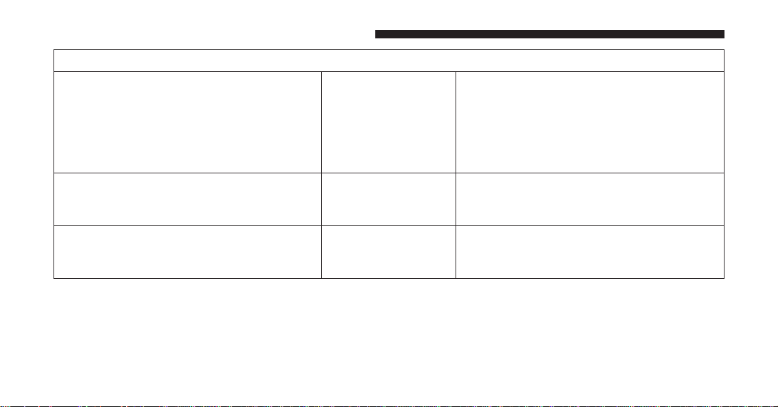
Frequently Asked Questions About Installing Child Restraints With LATCH
What is the weight limit (child’s weight +
weight of the child restraint) for using the
LATCH anchorage system to attach the
child restraint?
65 lbs (29.5 kg) Use the LATCH anchorage system until
the combined weight of the child and the
child restraint is 65 lbs (29.5 kg). Use the
seat belt and tether anchor instead of the
LATCH system once the combined weight
is more than 65 lbs (29.5 kg).
Can the LATCH anchorages and the seat
belt be used together to attach a rear-
facing or forward-facing child restraint?
No Do not use the seat belt when you use the
LATCH anchorage system to attach a rear-
facing or forward-facing child restraint.
Can a child seat be installed in the center
position using the inner LATCH lower an-
chorages?
No Full bench rear seat only: Use the seat belt
and tether anchor to install a child seat in
the center seating position.
92 THINGS TO KNOW BEFORE STARTING YOUR VEHICLE

Frequently Asked Questions About Installing Child Restraints With LATCH
Can two child restraints be attached using
a common lower LATCH anchorage?
No Never “share” a LATCH anchorage with
two or more child restraints. If the center
position does not have dedicated LATCH
lower anchorages, use the seat belt to in-
stall a child seat in the center position next
to a child seat using the LATCH anchor-
ages in an outboard position.
Can the rear-facing child restraint touch
the back of the front passenger seat?
Yes The child seat may touch the back of the
front passenger seat if the child restraint
manufacturer also allows contact. See your
child restraint owner’s manual for more
information.
Can the head restraints be removed? Yes The head restraints can be removed in
each seating position.
2
THINGS TO KNOW BEFORE STARTING YOUR VEHICLE 93
NOTE: If the folding, non-adjustable head restraint in-
terferes with the installation of the child restraint, the
head restraint may be folded and the child seat installed
in front of it.
WARNING!
Always make sure the head restraint is in its upright
position when the seat is to be used by an occupant
who is not in a child restraint. Sitting in a seat with
the head restraint in its lowered position could result
in serious injury or death in a collision.
Locating LATCH Anchorages
The lower anchorages are round bars that are
found at the rear of the seat cushion where it
meets the seatback. They are just visible when
you lean into the rear seat to install the child
restraint. You will easily feel them if you run your finger
along the gap between the seatback and seat cushion.
Quad Cab/Mega Cab/Crew Cab Rear Outboard Seats
Driver Side
94 THINGS TO KNOW BEFORE STARTING YOUR VEHICLE

Locating Tether Anchorages
Regular Cab models have tether strap anchor-
ages behind the front center and right seats.
Quad Cab, Mega Cab and Crew Cab models
have tether strap anchorages located behind
each of the rear seats.
1 — Tether Strap Hook
2 — Tether Strap To Child Restraint
3 — Tether Anchor
Standard Cab Tether Anchorages
2
THINGS TO KNOW BEFORE STARTING YOUR VEHICLE 95
LATCH-compatible child restraint systems will be
equipped with a rigid bar or a flexible strap on each side.
Each will have a hook or connector to attach to the lower
anchorage and a way to tighten the connection to the
anchorage. Forward-facing child restraints and some
rear-facing child restraints will also be equipped with a
tether strap. The tether strap will have a hook at the end
to attach to the top tether anchorage and a way to tighten
the strap after it is attached to the anchorage.
Center Seat LATCH — Regular Cab/Quad
Cab®/Crew Cab Full Bench
WARNING!
• Do not install a child restraint in the center posi-
tion using the LATCH system. This position is not
approved for installing child seats using the
LATCH attachments. You must use the seat belt
and tether anchor to install a child seat in the center
seating position.
• Never use the same lower anchorage to attach more
than one child restraint. Please refer to “Installing
The LATCH-Compatible Child Restraint System”
for typical installation instructions.
Mega Cab® Tether Anchorages (Behind Covers)
96 THINGS TO KNOW BEFORE STARTING YOUR VEHICLE
Center Seat LATCH — Mega Cab/Crew Cab Split
Bench
If a child restraint installed in the center position blocks
the seat belt webbing or buckle for the outboard position,
do not use that outboard position. If a child seat in the
center position blocks the outboard LATCH anchors or
seat belt, do not install a child seat in that outboard
position.
WARNING!
Never use the same lower anchorage to attach more
than one child restraint. Please refer to “Installing
The LATCH-Compatible Child Restraint System” for
typical installation instructions.
Always follow the directions of the child restraint manu-
facturer when installing your child restraint. Not all child
restraint systems will be installed as described here.
To Install A LATCH-Compatible Child Restraint
If the selected seating position has a Switchable Auto-
matic Locking Retractor (ALR) seat belt, stow the seat
belt, following the instructions below. See the section
“Installing Child Restraints Using the Vehicle Seat Belt”
to check what type of seat belt each seating position has.
1. Loosen the adjusters on the lower straps and on the
tether strap of the child seat so that you can more
easily attach the hooks or connectors to the vehicle
anchorages.
2. Place the child seat between the lower anchorages for
that seating position. For some second row seats, you
may need to recline the seat and / or raise the head
restraint to get a better fit. If the rear seat can be moved
forward and rearward in the vehicle, you may wish to
move it to its rear-most position to make room for the
child seat. You may also move the front seat forward
to allow more room for the child seat.
2
THINGS TO KNOW BEFORE STARTING YOUR VEHICLE 97

3. Attach the lower hooks or connectors of the child
restraint to the lower anchorages in the selected seat-
ing position.
4. If the child restraint has a tether strap, connect it to the
top tether anchorage. See the section “Installing Child
Restraints Using the Top Tether Anchorage” for direc-
tions to attach a tether anchor.
5. Tighten all of the straps as you push the child restraint
rearward and downward into the seat. Remove slack
in the straps according to the child restraint manufac-
turer’s instructions.
6. Test that the child restraint is installed tightly by
pulling back and forth on the child seat at the belt
path. It should not move more than 1 inch (25.4 mm)
in any direction.
How To Stow An Unused ALR Seat Belt:
When using the LATCH attaching system to install a
child restraint, stow all ALR seat belts that are not being
used by other occupants or being used to secure child
restraints. An unused belt could injure a child if they play
with it and accidentally lock the seat belt retractor. Before
installing a child restraint using the LATCH system,
buckle the seat belt behind the child restraint and out of
the child’s reach. If the buckled seat belt interferes with
the child restraint installation, instead of buckling it
behind the child restraint, route the seat belt through the
child restraint belt path and then buckle it. Do not lock
the seat belt. Remind all children in the vehicle that the
seat belts are not toys and that they should not play with
them.
98 THINGS TO KNOW BEFORE STARTING YOUR VEHICLE

WARNING!
• Improper installation of a child restraint to the
LATCH anchorages can lead to failure of the re-
straint. The child could be badly injured or killed.
Follow the child restraint manufacturer’s directions
exactly when installing an infant or child restraint.
• Child restraint anchorages are designed to with-
stand only those loads imposed by correctly-fitted
child restraints. Under no circumstances are they to
be used for adult seat belts, harnesses, or for
attaching other items or equipment to the vehicle.
Installing Child Restraints Using The Vehicle Seat
Belt
The seat belts in the passenger seating positions are
equipped with either a Switchable Automatic Locking
Retractor (ALR) or a cinching latch plate or both. Both
types of seat belts are designed to keep the lap portion of
the seat belt tight around the child restraint so that it is
not necessary to use a locking clip. The ALR retractor can
be “switched” into a locked mode by pulling all of the
webbing out of the retractor and then letting the webbing
retract back into the retractor. If it is locked, the ALR will
make a clicking noise while the webbing is pulled back
into the retractor. Refer to the “Automatic Locking
Mode” description under “Occupant Restraints” for ad-
ditional information on ALR. The cinching latch plate is
designed to hold the lap portion of the seat belt tight
when webbing is pulled tight and straight through a
child restraint’s belt path.
2
THINGS TO KNOW BEFORE STARTING YOUR VEHICLE 99

Lap/Shoulder Belt Systems For Installing Child
Restraints In This Vehicle
Regular Cab
• ALR = Switchable Automatic Locking Retractor
• Cinch = Cinching Latch Plate
•
Top Tether Anchorage Symbol
Quad Cab/Mega Cab/Crew Cab
• ALR = Switchable Automatic Locking Retractor
• Cinch = Cinching Latch Plate
•
Top Tether Anchorage Symbol
100 THINGS TO KNOW BEFORE STARTING YOUR VEHICLE

Lap/Shoulder Belt Systems
Frequently Asked Questions About Installing Child Restraints With Seat Belts
What is the weight limit (child’s weight +
weight of the child restraint) for using the
Tether Anchor with the seat belt to attach a
forward facing child restraint?
Weight limit of the
Child Restraint
Always use the tether anchor when using
the seat belt to install a forward facing
child restraint, up to the recommended
weight limit of the child restraint.
Can the rear-facing child restraint touch
the back of the front passenger seat?
Yes Contact between the front passenger seat
and the child restraint is allowed, if the
child restraint manufacturer also allows
contact.
Can the head restraints be removed? Yes The head restraints can be removed in
each seating position.
Can the buckle stalk be twisted to tighten
the seat belt against the belt path of the
child restraint?
Yes In positions with cinching latch plates
(CINCH), the buckle stalk may be twisted
up to 3 full turns. Do not twist the buckle
stalk in a seating position with an ALR
retractor.
2
THINGS TO KNOW BEFORE STARTING YOUR VEHICLE 101
WARNING!
Always make sure the head restraint is in its upright
position when the seat is to be used by an occupant
who is not in a child restraint. Sitting in a seat with
the head restraint in its lowered position could result
in serious injury or death in a collision.
Installing A Child Restraint With A Switchable
Automatic Locking Retractor (ALR)
1. Place the child seat in the center of the seating
position. For some second row seats, you may need to
recline the seat and/or raise the head restraint to get a
better fit. If the rear seat can be moved forward and
rearward in the vehicle, you may wish to move it to its
rear-most position to make room for the child seat.
You may also move the front seat forward to allow
more room for the child seat.
2. Pull enough of the seat belt webbing from the retractor
to pass it through the belt path of the child restraint.
Do not twist the belt webbing in the belt path.
3. Slide the latch plate into the buckle until you hear a
“click.”
4. Pull on the webbing to make the lap portion tight
against the child seat.
5. To lock the seat belt, pull down on the shoulder part of
the belt until you have pulled all the seat belt webbing
out of the retractor. Then, allow the webbing to retract
back into the retractor. As the webbing retracts, you
will hear a clicking sound. This means the seat belt is
now in the Automatic Locking mode.
6. Try to pull the webbing out of the retractor. If it is
locked, you should not be able to pull out any web-
bing. If the retractor is not locked, repeat step 5.
102 THINGS TO KNOW BEFORE STARTING YOUR VEHICLE

7. Finally, pull up on any excess webbing to tighten the
lap portion around the child restraint while you push
the child restraint rearward and downward into the
vehicle seat.
8. If the child restraint has a top tether strap and the
seating position has a top tether anchorage, connect
the tether strap to the anchorage and tighten the tether
strap. See the section “Installing Child Restraints
Using the Top Tether Anchorage” for directions to
attach a tether anchor.
9. Test that the child restraint is installed tightly by
pulling back and forth on the child seat at the belt
path. It should not move more than 1 inch (25.4 mm)
in any direction.
Any seat belt system will loosen with time, so check the
belt occasionally, and pull it tight if necessary.
Installing A Child Restraint With A Cinching
Latch Plate (CINCH) — If Equipped:
1. Place the child seat in the center of the seating
position. For some second row seats, you may need to
recline the seat and / or raise the head restraint to get
a better fit. If the rear seat can be moved forward and
rearward in the vehicle, you may wish to move it to its
rear-most position to make room for the child seat.
You may also move the front seat forward to allow
more room for the child seat.
2. Next, pull enough of the seat belt webbing from the
retractor to pass it through the belt path of the child
restraint. Do not twist the belt webbing in the belt
path.
3. Slide the latch plate into the buckle until you hear a
“click.”
2
THINGS TO KNOW BEFORE STARTING YOUR VEHICLE 103

4. Finally, pull up on any excess webbing to tighten the
lap portion around the child restraint while you push
the child restraint rearward and downward into the
vehicle seat.
5. If the child restraint has a top tether strap and the
seating position has a top tether anchorage, connect
the tether strap to the anchorage and tighten the tether
strap. See the section “Installing Child Restraints
Using the Top Tether Anchorage” for directions to
attach a tether anchor.
6. Test that the child restraint is installed tightly by
pulling back and forth on the child seat at the belt
path. It should not move more than 1 inch (25.4 mm)
in any direction.
Any seat belt system will loosen with time, so check the
belt occasionally, and pull it tight if necessary.
If the buckle or the cinching latch plate is too close to the
belt path opening of the child restraint, you may have
trouble tightening the seat belt. If this happens, discon-
nect the latch plate from the buckle and twist the short
buckle-end belt up to three full turns to shorten it. Insert
the latch plate into the buckle with the release button
facing out, away from the child restraint. Repeat steps 4
to 6, above, to complete the installation of the child
restraint.
If the belt still cannot be tightened after you shorten the
buckle, disconnect the latch plate from the buckle, turn
the buckle around one half turn, and insert the latch plate
into the buckle again. If you still cannot make the child
restraint installation tight, try a different seating position.
104 THINGS TO KNOW BEFORE STARTING YOUR VEHICLE
Installing Child Restraints Using The Top Tether
Anchorage
WARNING!
Do not attach a tether strap for a rear-facing car seat
to any location in front of the car seat, including the
seat frame or a tether anchorage. Only attach the
tether strap of a rear-facing car seat to the tether
anchorage that is approved for that seating position,
located behind the top of the vehicle seat. See the
section “Lower Anchors and Tethers for CHildren
(LATCH) Restraint System” for the location of ap-
proved tether anchorages in your vehicle.
Regular and Mega Cab® Trucks:
In the regular cab truck, the top tether anchorages are
located behind the center and right passenger seats. In
the mega cab truck, the top tether anchorages are located
behind each rear seating position. There is a plastic cover
over each anchorage. To attach the tether strap of the
child restraint:
1. Place the child restraint on the seat and adjust the
tether strap so that it will reach over the seat back,
under the head restraint and to the tether anchor
directly behind the seat.
2
THINGS TO KNOW BEFORE STARTING YOUR VEHICLE 105

1 — Tether Strap Hook
2 — Tether Strap to Child Restraint
3 — Tether Anchor
2. Route the tether strap to provide the most direct path
between the anchorage and the child seat. The tether
strap should go between the head restraint posts
underneath the head restraint. You may need to adjust
the head restraint to the upward position to pass the
tether strap underneath the head restraint and be-
tween its posts.
3. Lift the cover (if so equipped), and attach the hook to
the square opening in the sheet metal. Tighten the
tether strap according to the child seat manufacturer’s
instructions.
Regular Cab Tether Anchorages
106 THINGS TO KNOW BEFORE STARTING YOUR VEHICLE
WARNING!
Never place a rear-facing child restraint in front of an
air bag. A deploying Passenger Advanced Front Air
Bag can cause death or serious injury to a child 12
years or younger, including a child in a rear-facing
child restraint.
Quad Cab® or Crew Cab Trucks:
The top tether anchorages in this vehicle are tether strap
loops located between the rear glass and the back of the
rear seat. There is a tether strap loop located behind each
seating position. Follow the steps below to attach the
tether strap of the child restraint.
Mega Cab® Tether Anchorages
2
THINGS TO KNOW BEFORE STARTING YOUR VEHICLE 107

Right or Left Outboard Seats:
1. Raise the head restraint and reach between the rear
seat and rear glass to access the tether strap loop.
2. Place a child restraint on the seat and adjust the tether
strap so that it will reach over the seat back, under the
head restraint, through the tether strap loop behind
the seat and over to the tether strap loop behind the
center seat.
Head Restraint In Raised Position
Tether Strap Loop With Center Head Restraint In Raised
Position
108 THINGS TO KNOW BEFORE STARTING YOUR VEHICLE

3. Pass the tether strap hook under the head restraint
behind the child seat, though the tether strap loop
behind the seat and over to the center tether strap
loop.
4. Attach the hook to the center tether strap loop (see
diagram). Tighten the tether strap according to the
child seat manufacturer’s instructions.
Tether Strap Through Outboard Tether Strap Loop
Tether Strap Through Outboard Tether Strap Loop And
Attached To Center Tether Strap Loop
2
THINGS TO KNOW BEFORE STARTING YOUR VEHICLE 109

NOTE: If there are child seats in both of the outboard (left
and right) seating positions, the tether strap hooks of
both child seats should be connected to the center tether
strap loop. This is the correct way to tether two outboard
child seats.
Center Seat:
1. Raise the head restraint and reach between the rear
seat and rear glass to access the tether strap loop.
2. Place a child restraint on the seat and adjust the tether
strap so that it will reach over the seat back, under the
head restraint, through the tether strap loop behind
the seat and over to the tether strap loop behind either
the right or left outboard seat.
Tether Strap Loop With Head Restraint In Raised
Position
110 THINGS TO KNOW BEFORE STARTING YOUR VEHICLE

3. Pass the tether strap hook under the head restraint
behind the child seat, though the tether strap loop
behind the seat and over to the right or left outboard
tether strap loop.
4. Attach the hook to the outboard tether strap loop (see
diagram). Tighten the tether strap according to the
child seat manufacturer’s instructions.
Tether Strap Through Center Tether Strap Loop
Tether Strap Through Center Tether Strap Loop And
Attached To Outboard Tether Strap Loop
2
THINGS TO KNOW BEFORE STARTING YOUR VEHICLE 111
Installing Three Child Restraints:
1. Place a child restraint on each outboard rear seat.
Route the tether straps following the directions for
right and left seating positions, above.
2. Attach both hooks to the center tether strap loop, but
do not tighten the straps yet.
3. Place a child restraint on the center rear seat. Route the
tether strap following the directions for the center
seating position, above.
4. Attach the hook to the outboard tether strap loop.
5. Tighten the tether straps according to the child seat
manufacturer’s instructions, tightening the right and
left tether straps before the center tether strap.
WARNING!
• An incorrectly anchored tether strap could lead to
increased head motion and possible injury to the
child. Use only the anchorage position directly
(Continued)
Left Outboard And Center Seating Position Shown
112 THINGS TO KNOW BEFORE STARTING YOUR VEHICLE
WARNING! (Continued)
behind the child seat to secure a child restraint top
tether strap.
• If your vehicle is equipped with a split rear seat,
make sure the tether strap does not slip into the
opening between the seatbacks as you remove
slack in the strap.
Transporting Pets
Air Bags deploying in the front seat could harm your pet.
An unrestrained pet will be thrown about and possibly
injured, or injure a passenger during panic braking or in
a collision.
Pets should be restrained in the rear seat in pet harnesses
or pet carriers that are secured by seat belts.
ENGINE BREAK-IN RECOMMENDATIONS
A long break-in period is not required for the engine and
drivetrain (transmission and axle) in your vehicle.
Drive moderately during the first 300 miles (500 km).
After the initial 60 miles (100 km), speeds up to 50 or
55 mph (80 or 90 km/h) are desirable.
While cruising, brief full-throttle acceleration within the
limits of local traffic laws contributes to a good break-in.
Wide-open throttle acceleration in low gear can be detri-
mental and should be avoided.
The engine oil installed in the engine at the factory is a
high-quality energy conserving type lubricant. Oil
changes should be consistent with anticipated climate
conditions under which vehicle operations will occur. For
the recommended viscosity and quality grades, refer to
“Maintenance Procedures” in “Maintaining Your Ve-
hicle.”
2
THINGS TO KNOW BEFORE STARTING YOUR VEHICLE 113

CAUTION!
Never use Non-Detergent Oil or Straight Mineral Oil
in the engine or damage may result.
NOTE: A new engine may consume some oil during its
first few thousand miles (kilometers) of operation. This
should be considered a normal part of the break-in and
not interpreted as a problem.
SAFETY TIPS
Transporting Passengers
NEVER TRANSPORT PASSENGERS IN THE CARGO
AREA.
WARNING!
• Do not leave children or animals inside parked
vehicles in hot weather. Interior heat build-up may
cause serious injury or death.
• It is extremely dangerous to ride in a cargo area,
inside or outside of a vehicle. In a collision, people
riding in these areas are more likely to be seriously
injured or killed.
• Do not allow people to ride in any area of your
vehicle that is not equipped with seats and seat
belts.
• Be sure everyone in your vehicle is in a seat and
using a seat belt properly.
114 THINGS TO KNOW BEFORE STARTING YOUR VEHICLE
Exhaust Gas
WARNING!
Exhaust gases can injure or kill. They contain carbon
monoxide (CO), which is colorless and odorless.
Breathing it can make you unconscious and can
eventually poison you. To avoid breathing (CO),
follow these safety tips:
• Do not run the engine in a closed garage or in
confined areas any longer than needed to move
your vehicle in or out of the area.
• If you are required to drive with the trunk/liftgate/
rear doors open, make sure that all windows are
closed and the climate control BLOWER switch is
set at high speed. DO NOT use the recirculation
mode.
(Continued)
WARNING! (Continued)
• If it is necessary to sit in a parked vehicle with the
engine running, adjust your heating or cooling
controls to force outside air into the vehicle. Set the
blower at high speed.
The best protection against carbon monoxide entry into
the vehicle body is a properly maintained engine exhaust
system.
Whenever a change is noticed in the sound of the exhaust
system, when exhaust fumes can be detected inside the
vehicle, or when the underside or rear of the vehicle is
damaged, have a competent mechanic inspect the com-
plete exhaust system and adjacent body areas for broken,
damaged, deteriorated, or mispositioned parts. Open
seams or loose connections could permit exhaust fumes
to seep into the passenger compartment. In addition,
inspect the exhaust system each time the vehicle is raised
for lubrication or oil change. Replace as required.
2
THINGS TO KNOW BEFORE STARTING YOUR VEHICLE 115

Safety Checks You Should Make Inside The
Vehicle
Seat Belts
Inspect the seat belt system periodically, checking for
cuts, frays, and loose parts. Damaged parts must be
replaced immediately. Do not disassemble or modify the
system.
Front seat belt assemblies must be replaced after a
collision. Rear seat belt assemblies must be replaced after
a collision if they have been damaged (i.e., bent retractor,
torn webbing, etc.). If there is any question regarding seat
belt or retractor condition, replace the seat belt.
Air Bag Warning Light
The light should come on and remain on for
four to eight seconds as a bulb check when the
ignition switch is first turned ON. If the light is
not lit during starting, see your authorized dealer. If the
light stays on, flickers, or comes on while driving, have
the system checked by an authorized dealer.
Defroster
Check operation by selecting the defrost mode and place
the blower control on high speed. You should be able to
feel the air directed against the windshield. See your
authorized dealer for service if your defroster is inoper-
able.
Floor Mat Safety Information
Always use floor mats designed to fit the footwell of your
vehicle. Use only floor mats that leave the pedal area
unobstructed and that are firmly secured so that they
cannot slip out of position and interfere with the pedals
or impair safe operation of your vehicle in other ways.
116 THINGS TO KNOW BEFORE STARTING YOUR VEHICLE
WARNING!
Pedals that cannot move freely can cause loss of
vehicle control and increase the risk of serious per-
sonal injury.
• Always make sure that floor mats are properly
attached to the floor mat fasteners.
• Never place or install floor mats or other floor
coverings in the vehicle that cannot be properly
secured to prevent them from moving and interfer-
ing with the pedals or the ability to control the
vehicle.
• Never put floor mats or other floor coverings on top
of already installed floor mats. Additional floor
mats and other coverings will reduce the size of the
pedal area and interfere with the pedals.
(Continued)
WARNING! (Continued)
• Check mounting of mats on a regular basis. Always
properly reinstall and secure floor mats that have
been removed for cleaning.
• Always make sure that objects cannot fall into the
driver footwell while the vehicle is moving. Ob-
jects can become trapped under the brake pedal
and accelerator pedal causing a loss of vehicle
control.
• If required, mounting posts must be properly in-
stalled, if not equipped from the factory.
Failure to properly follow floor mat installation or
mounting can cause interference with the brake
pedal and accelerator pedal operation causing loss of
control of the vehicle.
2
THINGS TO KNOW BEFORE STARTING YOUR VEHICLE 117

Periodic Safety Checks You Should Make Outside
The Vehicle
Tires
Examine tires for excessive tread wear and uneven wear
patterns. Check for stones, nails, glass, or other objects
lodged in the tread or sidewall. Inspect the tread for cuts
and cracks. Inspect sidewalls for cuts, cracks, and bulges.
Check the wheel bolts for tightness. Check the tires
(including spare) for proper cold inflation pressure.
Lights
Have someone observe the operation of brake lights and
exterior lights while you work the controls. Check turn
signal and high beam indicator lights on the instrument
panel.
Door Latches
Check for proper closing, latching, and locking.
Fluid Leaks
Check area under vehicle after overnight parking for fuel,
engine coolant, oil, or other fluid leaks. Also, if gasoline
fumes are detected or if fuel, power steering fluid (if
equipped), or brake fluid leaks are suspected. The cause
should be located and corrected immediately.
118 THINGS TO KNOW BEFORE STARTING YOUR VEHICLE

UNDERSTANDING THE FEATURES OF YOUR VEHICLE
CONTENTS
䡵 MIRRORS ............................126
▫ Inside Day/Night Mirror — If Equipped . . . .126
▫ Automatic Dimming Mirror — If Equipped . . .126
▫ Automatic Dimming Mirror With Rear View
Camera Display — If Equipped ...........133
▫ Outside Mirrors ......................134
▫ Outside Mirrors Folding Feature ...........135
▫ Tilt Mirrors In Reverse — If Equipped .......136
▫ Power Folding Outside Mirrors For Standard And
Trailer Tow — If Equipped ...............136
▫ Power Mirrors — If Equipped ............138
▫ Heated Mirrors — If Equipped ...........140
▫ Driver’s Outside Automatic Dimming Mirror — If
Equipped ...........................140
▫ Trailer Towing Mirrors — If Equipped ......140
▫ Illuminated Vanity Mirror — If Equipped . . . .141
▫ “Slide-On-Rod” Features Of Sun Visor — If
Equipped ...........................142
䡵 SEATS ..............................142
▫ Driver’s Power Seat — If Equipped ........143
3

▫ Passenger’s Power Seat — If Equipped ......145
▫ Power Lumbar — If Equipped ............145
▫ Heated Seats — If Equipped ..............146
▫ Ventilated Seats — If Equipped ............148
▫ Manual Seat Adjuster — If Equipped........150
▫ 40-20-40 Front Bench Seat — If Equipped . . . .151
▫ Mega Cab® Rear Seat Features ............151
▫ Head Restraints ......................155
䡵 DRIVER MEMORY SEAT — IF EQUIPPED . . . .159
▫ Programming The Memory Feature .........159
▫ Linking And Unlinking The Remote Keyless Entry
Transmitter To Memory .................160
▫ Memory Position Recall .................161
▫ Easy Entry/Exit Seat ...................162
䡵 TO OPEN AND CLOSE THE HOOD .........164
䡵 LIGHTS .............................165
▫ Headlights ..........................166
▫ Automatic Headlights — If Equipped .......167
▫ Headlights On With Wipers (Available With
Automatic Headlights Only) ..............167
▫ Daytime Running Lights (DRL) — If
Equipped ...........................168
▫ Headlight Delay ......................168
▫ Automatic High Beam Headlamp Control — If
Equipped ...........................169
120 UNDERSTANDING THE FEATURES OF YOUR VEHICLE

▫ Parking Lights And Panel Lights...........171
▫ Fog Lights — If Equipped ...............171
▫ Lights-On Reminder ...................172
▫ Battery Saver.........................172
▫ Interior Lights .......................172
▫ Cargo Light .........................175
▫ Multifunction Lever ...................176
▫ Turn Signals .........................176
▫ Lane Change Assist ...................177
▫ Flash-To-Pass ........................177
▫ High/Low Beam Switch ................177
䡵 WINDSHIELD WIPERS AND WASHERS ......178
▫ Windshield Wipers ....................178
▫ Windshield Wiper Operation .............178
▫ Intermittent Wiper System ...............178
▫ Windshield Washers ...................179
▫ Mist Feature .........................179
▫ Rain Sensing Wipers — If Equipped ........180
䡵 TILT STEERING COLUMN ...............181
䡵 HEATED STEERING WHEEL — IF EQUIPPED .182
䡵 DRIVER ADJUSTABLE PEDALS — IF
EQUIPPED ...........................184
䡵 ELECTRONIC SPEED CONTROL ...........185
▫ To Activate ..........................186
▫ To Set A Desired Speed .................187
▫ To Deactivate ........................187
3
UNDERSTANDING THE FEATURES OF YOUR VEHICLE 121

▫ To Resume Speed .....................187
▫ To Vary The Speed Setting ...............188
▫ To Accelerate For Passing ................189
䡵 PARKSENSE® REAR PARK ASSIST — IF
EQUIPPED ...........................190
▫ ParkSense® Sensors ....................190
▫ ParkSense® Warning Display .............191
▫ ParkSense® Display ....................191
▫ Enabling And Disabling ParkSense® .......195
▫ Service The ParkSense® Rear Park Assist
System .............................196
▫ Cleaning The ParkSense® System ..........197
▫ ParkSense® System Usage Precautions.......197
䡵 PARKSENSE® FRONT AND REAR PARK ASSIST
— IF EQUIPPED .......................199
▫ ParkSense® Sensors ....................200
▫ ParkSense® Warning Display .............200
▫ ParkSense® Display ....................201
▫ Enabling And Disabling Front And/Or Rear
ParkSense®..........................203
▫ Service The ParkSense® Park Assist System . . .204
▫ Cleaning The ParkSense® System ..........205
▫ ParkSense® System Usage Precautions.......206
䡵 PARKVIEW® REAR BACK UP CAMERA — IF
EQUIPPED ...........................208
䡵 OVERHEAD CONSOLE — IF EQUIPPED .....210
▫ Courtesy/Reading Lights ...............211
122 UNDERSTANDING THE FEATURES OF YOUR VEHICLE

䡵 GARAGE DOOR OPENER — IF EQUIPPED . . .212
▫ Before You Begin Programming HomeLink® . .214
▫ Programming A Rolling Code ............215
▫ Programming A Non-Rolling Code .........217
▫ Canadian/Gate Operator Programming .....218
▫ Using HomeLink® ....................220
▫ Security ............................220
▫ Troubleshooting Tips ...................220
▫ General Information....................221
䡵 POWER SUNROOF — IF EQUIPPED ........222
▫ Opening Sunroof — Manual Mode .........223
▫ Closing Sunroof — Manual Mode ..........223
▫ Opening Sunroof — Express ..............223
▫ Closing Sunroof — Express...............224
▫ Pinch Protect Feature ...................224
▫ Venting Sunroof — Express ..............224
▫ Sunshade Operation....................224
▫ Wind Buffeting .......................225
▫ Sunroof Maintenance ...................225
▫ Ignition Off Operation ..................225
䡵 ELECTRICAL POWER OUTLETS ...........225
䡵 CIGAR LIGHTER AND ASH RECEIVER — IF
EQUIPPED ...........................231
䡵 POWER INVERTER — IF EQUIPPED ........232
䡵 AUXILIARY SWITCHES — IF EQUIPPED .....233
3
UNDERSTANDING THE FEATURES OF YOUR VEHICLE 123

䡵 CUPHOLDERS ........................234
▫ Front Seat Cupholders (40–20–40 Seats) ......234
▫ Front Instrument Panel Cupholders — Floor
Mounted Shifter ......................234
▫ Rear Cupholders — If Equipped ...........235
䡵 STORAGE ............................236
▫ Glove Compartment ...................236
▫ Door Storage.........................238
▫ Center Storage Compartment — If Equipped . .239
▫ Second Row In-Floor Storage Bin — If
Equipped ...........................241
▫ Seatback Storage ......................242
▫ Storage (Regular Cab) ..................243
▫ Storage and Seats (Crew Cab) .............243
▫ Plastic Grocery Bag Retainers
(Regular Cab Models) ..................244
䡵 REAR WINDOW FEATURES ..............245
▫ Rear Window Defroster .................245
▫ Power Sliding Rear Window — If Equipped . .246
▫ Manual Sliding Rear Window — If Equipped .246
䡵 FOLD FLAT LOAD FLOOR — IF EQUIPPED . .246
䡵 PICKUP BOX .........................251
▫ Cargo Camera — If Equipped .............252
▫ Turning Cargo Camera On Or Off — With
Uconnect® 8.4A/8.4AN .................253
124 UNDERSTANDING THE FEATURES OF YOUR VEHICLE

䡵 RAMBOX® — IF EQUIPPED ..............253
▫ RamBox® Integrated Box Side Storage Bins . . .254
▫ Locking And Unlocking RamBox® .........256
▫ RamBox® Safety Warning................257
▫ Bed Extender — If Equipped .............258
▫ Bed Rail Tie-Down System ..............265
䡵 SLIDE-IN CAMPERS ....................267
▫ Camper Applications ...................267
䡵 EASY-OFF TAILGATE ...................267
▫ Disconnecting The Rear Camera Or Remote
Keyless Entry — If Equipped .............267
▫ Removing The Tailgate..................268
▫ Locking Tailgate ......................269
䡵 TRI-FOLD TONNEAU COVER — IF
EQUIPPED ...........................270
▫ Tri-Fold Tonneau Cover Removal ..........270
▫ Tri-Fold Tonneau Cover Installation.........274
▫ Tri-Fold Tonneau Cover Cleaning ..........280
3
UNDERSTANDING THE FEATURES OF YOUR VEHICLE 125

MIRRORS
Inside Day/Night Mirror — If Equipped
A single ball joint mirror is provided in the vehicle. It is
a twist on mirror that has a fixed position at the wind-
shield. The mirror installs on the windshield button with
a counterclockwise rotation and requires no tools for
mounting. The mirror head can be adjusted up, down,
left, and right for various drivers. The mirror should be
adjusted to center on the view through the rear window.
Headlight glare from vehicles behind you can be reduced
by moving the small control under the mirror to the night
position (toward the rear of the vehicle). The mirror
should be adjusted while the small control under the
mirror is set in the day position (toward the windshield).
Automatic Dimming Mirror — If Equipped
A single ball joint mirror is provided in the vehicle. It is
a twist on mirror that has a fixed position at the wind-
shield. The mirror installs on the windshield button with
a counterclockwise rotation and requires no tools for
mounting. The mirror head can be adjusted up, down,
Adjusting Rearview Mirror
126 UNDERSTANDING THE FEATURES OF YOUR VEHICLE

left, and right for various drivers. The mirror should be
adjusted to center on the view through the rear window.
This mirror automatically adjusts for headlight glare
from vehicles behind you.
NOTE: The Automatic Dimming Mirror feature is dis-
abled when the vehicle is in reverse gear to improve rear
view viewing.
The Automatic Dimming Mirror feature can be turned
On or Off through the touchscreen.
• Push the Mirror Dimmer button once to turn the
feature On.
• Push the Mirror Dimmer button a second time to turn
the feature Off.
If equipped, the rearview mirror contains an ASSIST and
a 9-1-1 button.
Automatic Dimming Mirror
3
UNDERSTANDING THE FEATURES OF YOUR VEHICLE 127

NOTE: The ASSIST and 9–1–1 features operate through
the Uconnect® Access service. These buttons will only
operate as long as your Uconnect® Access service is
active. Refer to your “Uconnect® System supplement
manual” for further information.
ASSIST Call
The ASSIST Button is used to automatically connect you
to any one of the following support centers:
• Roadside Assistance – If you get a flat tire, or need a
tow, just push the Assist button and you’ll be con-
nected to someone who can help. Roadside Assistance
will know what vehicle you’re driving and its location.
Additional fees may apply for roadside Assistance.
• Uconnect® Access Customer Care – In-vehicle support
for Uconnect® Access and Uconnect® Access Via
Mobile features.
• Vehicle Customer Care – Total support for all other
vehicle issues.
9-1-1 Call
1. Push the 9-1-1 Call button on the Rearview Mirror.
NOTE: In case the 9-1-1 Call button is pushed in error,
there will be a 10 second delay before the 9-1-1 Call
system initiates a call to a 9-1-1 operator. To cancel the
9-1-1 Call connection, push the 9-1-1 Call button on the
Rearview Mirror or press the cancellation button on the
Phone Screen. Termination of the 9-1-1 Call will turn off
the green LED light on the Rearview Mirror.
2. The LED light located between the Assist and 9-1-1
buttons on the Rearview Mirror will turn green once a
connection to a 9-1-1 operator has been made.
128 UNDERSTANDING THE FEATURES OF YOUR VEHICLE
3. Once a connection between the vehicle and a 9-1-1
operator is made, the 9-1-1 Call system may transmit
the following important vehicle information to a 9-1-1
operator:
• Indication that the occupant placed a 9-1-1 Call.
• The vehicle brand.
• The last known GPS coordinates of the vehicle.
4. You should be able to speak with the 9-1-1 operator
through the vehicle audio system to determine if
additional help is needed.
NOTE: Once a connection is made between the vehicle’s
9-1-1 Call system and the 9-1-1 operator, the 9-1-1 opera-
tor may be able to open a voice connection with the
vehicle to determine if additional help is needed. Once
the 9-1-1 operator opens a voice connection with the
vehicle’s 9-1-1 Call system, the operator should be able to
speak with you or other vehicle occupants and hear
sounds occurring in the vehicle. The vehicle’s 9-1-1 Call
system will attempt to remain connected with the 9-1-1
operator until the 9-1-1 operator terminates the connec-
tion.
5. The 9-1-1 operator may attempt to contact appropriate
emergency responders and provide them with impor-
tant vehicle information and GPS coordinates.
WARNING!
• If anyone in the vehicle could be in danger (e.g.,
fire or smoke is visible, dangerous road conditions
or location), do not wait for voice contact from a
9-1-1 operator. All occupants should exit the vehicle
immediately and move to a safe location.
• Never place anything on or near the vehicle’s
wireless and GPS antennas. You could prevent
(Continued)
3
UNDERSTANDING THE FEATURES OF YOUR VEHICLE 129
WARNING! (Continued)
wireless and GPS signal reception, which can pre-
vent your vehicle from placing an emergency call.
Wireless and GPS signal reception is required for
the 9-1-1 Call system to function properly.
• The 9-1-1 Call system is embedded into the vehi-
cle’s electrical system. Do not add aftermarket
electrical equipment to the vehicle’s electrical sys-
tem. This may prevent your vehicle from sending a
signal to initiate an emergency call. To avoid inter-
ference that can cause the 9-1-1 Call system to fail,
never add aftermarket equipment (e.g., two-way
mobile radio, CB radio, data recorder, etc.) to your
vehicle’s electrical system or modify the antennas
on your vehicle. IF YOUR VEHICLE LOSES BAT-
TERY POWER FOR ANY REASON (INCLUDING
DURING OR AFTER AN ACCIDENT), THE
(Continued)
WARNING! (Continued)
UCONNECT FEATURES, APPS AND SERVICES,
AMONG OTHERS, WILL NOT OPERATE.
• Modifications to any part of the 9-1-1 Call system
could cause the air bag system to fail when you
need it. You could be injured if the air bag system
is not there to help protect you.
9-1-1 Call System Limitations
Vehicles sold in Canada and Mexico DO NOT have 9-1-1
Call system capabilities.
9-1-1 or other emergency line operators in Canada and
Mexico may not answer or respond to 9-1-1 system calls.
130 UNDERSTANDING THE FEATURES OF YOUR VEHICLE
If the 9-1-1 Call system detects a malfunction, any of the
following may occur at the time the malfunction is
detected, and at the beginning of each ignition cycle:
• The Rearview Mirror light located between the Assist
and 9-1-1 buttons will continuously be illuminated
red.
• The Phone Screen will display the following message
“Vehicle phone requires service. Please contact your
dealer.”
• An In-Vehicle Audio message will state “Vehicle phone
requires service. Please contact your dealer.”
WARNING!
• Ignoring the Rearview Mirror light could mean you
will not have 9-1-1 Call services. If the Rearview
Mirror light is illuminated, have an authorized
dealer service the 9-1-1 Call system immediately.
• The Occupant Restraint Control module turns on
the Air Bag Warning Light on the instrument panel
if a malfunction in any part of the system is
detected. If the Air Bag Warning Light is illumi-
nated, the air bag system may not be working
properly and the 9-1-1 system may not be able to
send a signal to a 9-1-1 operator. If the Air Bag
Warning Light is illuminated, have an authorized
dealer service the ORC system immediately.
3
UNDERSTANDING THE FEATURES OF YOUR VEHICLE 131

Even if the 9-1-1 Call system is fully functional, factors
beyond FCA US LLC’s control may prevent or stop the
9-1-1 Call system operation. These include, but are not
limited to, the following factors:
• Delayed accessories mode is active.
• The ignition is in the OFF position.
• The vehicle’s electrical systems are not intact.
• The 9-1-1 Call system software and/or hardware are
damaged during a crash.
• The vehicle battery loses power or becomes discon-
nected during a vehicle crash.
• Wireless and/or Global Positioning Satellite signals
are unavailable or obstructed.
• Equipment malfunction at the 9-1-1 operator facility.
• Operator error by the 9-1-1 operator.
• Wireless network congestion.
• Weather.
• Buildings, structures, geographic terrain, or tunnels.
NOTE: Never place anything on or near the vehicle’s
wireless and GPS antennas. You could prevent wireless
and GPS signal reception, which can prevent your vehicle
from placing an emergency call. Wireless and GPS signal
reception is required for the 9-1-1 Call system to function
properly.
132 UNDERSTANDING THE FEATURES OF YOUR VEHICLE
General Information
This device complies with Part 15 of the FCC Rules.
Operation is subject to the following two conditions: (1)
This device may not cause harmful interference, and (2)
this device must accept any interference received, includ-
ing interference that may cause undesired operation.
NOTE: Changes or modifications not expressly approved
by the party responsible for compliance could void the
user’s authority to operate the equipment.
CAUTION!
To avoid damage to the mirror during cleaning, never
spray any cleaning solution directly onto the mirror.
Apply the solution onto a clean cloth and wipe the
mirror clean.
Automatic Dimming Mirror With Rear View
Camera Display — If Equipped
A single ball joint mirror is provided in the vehicle. It is
a twist on mirror that has a fixed position at the wind-
shield. The mirror installs on the windshield button with
a counterclockwise rotation and requires no tools for
mounting. The mirror head can be adjusted up, down,
left, and right for various drivers. The mirror should be
adjusted to center on the view through the rear window.
This mirror automatically adjusts for headlight glare
from vehicles behind you.
3
UNDERSTANDING THE FEATURES OF YOUR VEHICLE 133
When the vehicle is placed into reverse gear a video
display illuminates to display the image generated by the
rear view camera located on the tailgate handle. The auto
dimming feature is also disabled to improve rear view
viewing.
Outside Mirrors
To receive maximum benefit, adjust the outside mirrors
to center on the adjacent lane of traffic with a slight
overlap of the view obtained on the inside mirror.
NOTE: If your vehicle is equipped with illuminated
approach lights under the outside mirrors they can be
turned off through the instrument cluster or the
Uconnect® radio. For further information refer to “EVIC”
or ”DID” and “Uconnect® Settings” in “Understanding
Your Instrument Panel”.
WARNING!
Vehicles and other objects seen in the passenger side
convex mirror will look smaller and farther away
than they really are. Relying too much on your
passenger side convex mirror could cause you to
(Continued)
Automatic Dimming Mirror With Rear View Camera
134 UNDERSTANDING THE FEATURES OF YOUR VEHICLE
WARNING! (Continued)
collide with another vehicle or other object. Use your
inside mirror when judging the size or distance of a
vehicle seen in the passenger side convex mirror.
Some vehicles will not have a convex passenger side
mirror.
Outside Mirrors Folding Feature
All outside mirrors are designed to be able to be manu-
ally folded both forward and rearward to prevent dam-
age.
CAUTION!
It is recommended to fold the mirrors into the full
rearward position to resist damage when entering a
car wash or a narrow location.
Folding Mirror
3
UNDERSTANDING THE FEATURES OF YOUR VEHICLE 135

Tilt Mirrors In Reverse — If Equipped
Tilt Mirrors in Reverse provides automatic outside mirror
positioning which will aid the driver’s view of the
ground rearward of the front doors. The outside mirrors
will move slightly downward from the present position
when the vehicle is shifted into REVERSE. The outside
mirrors will then return to the original position when the
vehicle is shifted out of the REVERSE position. Each
stored memory setting will have an associated Tilt Mir-
rors in Reverse position.
NOTE: The Tilt Mirrors in Reverse feature is not turned
on when delivered from the factory.
If your vehicle is equipped with a touchscreen, this
feature can be programmed through the Uconnect®
system. Refer to “Uconnect® Settings” in “Understand-
ing Your Instrument Panel” for further information.
If your vehicle is not equipped with a touchscreen, this
feature can be programmed through the Electronic Ve-
hicle Information Center (EVIC) or Driver Information
Display (DID). Refer to “Electronic Vehicle Information
Center (EVIC)” or “Driver Information Display (DID)” in
“Understanding Your Instrument Panel” for further in-
formation.
Power Folding Outside Mirrors For Standard And
Trailer Tow — If Equipped
If equipped with power folding mirrors, they can be
electrically folded rearward and unfolded into the drive
position.
The switch for the power folding mirrors is located
between the power mirror switches L (left) and R (right).
Push the switch once and the mirrors will fold in, push
the switch a second time and the mirrors will return to
the normal driving position.
136 UNDERSTANDING THE FEATURES OF YOUR VEHICLE

If the mirror is manually folded after electrically cycled,
a potential extra button push is required to get the
mirrors back to the home position. If the mirror does not
electrically fold check for ice or dirt build up at the pivot
area which can cause excessive drag.
Resetting the Power Folding Outside Mirrors
You may need to reset the power folding mirrors if the
following occurs:
• The mirrors are accidentally blocked while folding.
• The mirrors are accidentally manually folded/
unfolded.
• The mirrors come out of the unfolded position.
• The mirrors shake and vibrate at normal driving
speeds.
Power Folding Mirror Switch
3
UNDERSTANDING THE FEATURES OF YOUR VEHICLE 137

To reset the power folding mirrors: Fold and unfold them
by pushing the button (this may require multiple button
pushes). This resets them to their normal position.
NOTE:
• The power fold mirrors are designed to operate while
the vehicle is stationary or traveling at moderate
speeds. If you attempt to power fold the mirrors at
high speeds they may not fully open or close. You
should slow down to a moderate speed and complete
the operation.
• When pushing the power fold button 10 or more times
in one minute the system shuts down for one minute
to protect the motors from over heating.
Power Mirrors — If Equipped
The controls for the power mirrors are located on the
driver’s door trim panel.
Power Mirror Controls Location
138 UNDERSTANDING THE FEATURES OF YOUR VEHICLE

The power mirror controls consist of mirror select but-
tons and a four-way mirror control switch.
To adjust a mirror, push either the L (left) or R (right)
button to select the mirror that you want to adjust.
Using the mirror control switch, push on any of the four
arrows for the direction that you want the mirror to
move.
Power Mirror Controls
1 — Mirror Select Buttons
2 — Four-Way Mirror Control Switch
Power Mirror Movement
3
UNDERSTANDING THE FEATURES OF YOUR VEHICLE 139

Heated Mirrors — If Equipped
These mirrors are heated to melt frost or ice. This
feature can be activated whenever you turn on the
rear window defroster (if equipped). Refer to “Rear
Window Features” in “Understanding The Features Of
Your Vehicle” for further information.
Driver’s Outside Automatic Dimming Mirror — If
Equipped
The driver’s outside mirror will automatically adjust for
glare from vehicles behind you. This feature is controlled
by the inside automatic dimming mirror and will auto-
matically adjust for headlight glare when the inside
mirror adjusts.
Trailer Towing Mirrors — If Equipped
These mirrors are designed with an adjustable mirror
head to provide a greater vision range when towing
extra-wide loads. To change position inboard or out-
board, the mirror head should be rotated (flipped in or
out).
NOTE: Fold the trailer towing mirrors rearward prior to
entering an automated car wash.
Trailer Towing Position
140 UNDERSTANDING THE FEATURES OF YOUR VEHICLE

A small blindspot mirror is located next to main mirror
and can be adjusted separately.
Illuminated Vanity Mirror — If Equipped
Illuminated vanity mirrors are located on each sun visor.
To use the mirror, rotate the sun visor down and swing
the mirror cover upward. The lights will turn on auto-
matically. Closing the mirror cover turns off the light.
Blindspot Mirror
Illuminated Vanity Mirror
3
UNDERSTANDING THE FEATURES OF YOUR VEHICLE 141

“Slide-On-Rod” Features Of Sun Visor — If
Equipped
The sun visor “Slide-On-Rod” feature allows for addi-
tional flexibility in positioning the visor to block out the
sun.
To use the “Slide-On-Rod” feature, rotate the sun visor
downward and unclip it. Pull the sun visor along the
“Slide-On-Rod” until the sun visor is in the desired
position.
SEATS
Seats are a part of the Occupant Restraint System of the
vehicle.
“Slide-On-Rod” Extender
142 UNDERSTANDING THE FEATURES OF YOUR VEHICLE
WARNING!
• It is dangerous to ride in a cargo area, inside or
outside of a vehicle. In a collision, people riding in
these areas are more likely to be seriously injured
or killed.
• Do not allow people to ride in any area of your
vehicle that is not equipped with seats and seat
belts. In a collision, people riding in these areas are
more likely to be seriously injured or killed.
• Be sure everyone in your vehicle is in a seat and
using a seat belt properly.
Driver’s Power Seat — If Equipped
Some models may be equipped with an eight-way power
driver’s seat. The power seat switches are located on the
outboard side of the driver’s seat cushion. There are two
power seat switches that are used to control the move-
ment of the seat cushion and the seatback.
Adjusting The Seat Forward Or Rearward
The seat can be adjusted both forward and rearward.
Push the seat switch forward or rearward. The seat will
Power Seat Switches
1 — Power Seat Switch
2 — Power Seatback Switch
3
UNDERSTANDING THE FEATURES OF YOUR VEHICLE 143
move in the direction of the switch. Release the switch
when the desired position has been reached.
Adjusting The Seat Up Or Down
The height of the seats can be adjusted up or down. Pull
upward or push downward on the seat switch. The seat
will move in the direction of the switch. Release the
switch when the desired position is reached.
Tilting The Seat Up Or Down
The angle of the seat cushion can be adjusted in four
directions. Pull upward or push downward on the front
or rear of the seat switch, the front or rear of the seat
cushion will move in the direction of the switch. Release
the switch when the desired position is reached.
Reclining The Seatback
The angle of the seatback can be adjusted forward or
rearward. Push the seatback switch forward or rearward,
the seat will move in the direction of the switch. Release
the switch when the desired position is reached.
WARNING!
• Adjusting a seat while driving may be dangerous.
Moving a seat while driving could result in loss of
control which could cause a collision and serious
injury or death.
• Seats should be adjusted before fastening the seat
belts and while the vehicle is parked. Serious
injury or death could result from a poorly adjusted
seat belt.
• Do not ride with the seatback reclined so that the
shoulder belt is no longer resting against your
chest. In a collision you could slide under the seat
belt, which could result in serious injury or death.
144 UNDERSTANDING THE FEATURES OF YOUR VEHICLE
CAUTION!
Do not place any article under a power seat or impede
its ability to move as it may cause damage to the seat
controls. Seat travel may become limited if movement
is stopped by an obstruction in the seat’s path.
Passenger’s Power Seat — If Equipped
Some models are equipped with a six-way power pas-
senger seat. The power seat switch is located on the
outboard side of the seat. The switch is used to control
the movement of the seat and seat cushion.
Adjusting The Seat Forward Or Rearward
The seat can be adjusted both forward and rearward.
Push the seat switch forward or rearward. The seat will
move in the direction of the switch. Release the switch
when the desired position has been reached.
Power Lumbar — If Equipped
Vehicles equipped with power driver or passenger seats
may be also be equipped with power lumbar. The power
lumbar switch is located on the outboard side of the
power seat. Push the switch forward to increase the
lumbar support. Push the switch rearward to decrease
the lumbar support.
Lumbar Control Switch
3
UNDERSTANDING THE FEATURES OF YOUR VEHICLE 145
Heated Seats — If Equipped
On some models, the front and rear seats may be
equipped with heaters located in the seat cushions and
seat backs.
WARNING!
• Persons who are unable to feel pain to the skin
because of advanced age, chronic illness, diabetes,
spinal cord injury, medication, alcohol use, exhaus-
tion or other physical condition must exercise care
when using the seat heater. It may cause burns
even at low temperatures, especially if used for
long periods of time.
• Do not place anything on the seat or seatback that
insulates against heat, such as a blanket or cushion.
This may cause the seat heater to overheat. Sitting
in a seat that has been overheated could cause
(Continued)
WARNING! (Continued)
serious burns due to the increased surface tempera-
ture of the seat.
Front Heated Seats
The front heated seats control buttons are located on the
center instrument panel below the climate controls.
If your vehicle is equipped with a touchscreen, the front
heated seats control buttons are also located within the
climate or controls screen of the touchscreen.
• Press the heated seat button
once to turn the HI
setting On.
• Press the heated seat button
a second time to turn
the LO setting On.
• Press the heated seat button
a third time to turn
the heating elements OFF.
146 UNDERSTANDING THE FEATURES OF YOUR VEHICLE

When the HI-level setting is selected, the heater will
provide a boosted heat level during the first four minutes
of operation. Then, the heat output will drop to the
normal HI-level. If the HI-level setting is selected, the
system will automatically switch to LO-level after ap-
proximately 60 minutes of continuous operation. At that
time, the display will change from HI to LO, indicating
the change. The LO-level setting will turn OFF automati-
cally after approximately 45 minutes.
NOTE: The engine must be running for the heated seats
to operate.
Vehicles Equipped With Remote Start
On models that are equipped with remote start, the
heated seats can be programed to come on during a
remote start.
If your vehicle is equipped with a touchscreen, this
feature can be programmed through the Uconnect®
system. Refer to “Uconnect® Settings” in “Understand-
ing Your Instrument Panel” for further information.
If your vehicle is not equipped with a touchscreen, this
feature can be programmed through the Electronic Vehicle
Information Center (EVIC) or Driver Information Display
(DID). Refer to “Electronic Vehicle Information Center
(EVIC)” or “Driver Information Display (DID)” in “Under-
standing Your Instrument Panel” for further information.
Rear Heated Seats
On some models, the two outboard seats are equipped
with heated seats. The heated seat switches for these
seats are located on the rear of the center console.
3
UNDERSTANDING THE FEATURES OF YOUR VEHICLE 147

There are two heated seat switches that allow the rear
passengers to operate the seats independently. You can
choose from HI, LO or OFF heat settings. Amber indica-
tor lights in each switch indicate the level of heat in use.
Two indicator lights will illuminate for HI, one for LO
and none for OFF.
Push the switch once to select HI-level heating.
Push the switch a second time to select LO-
level heating. Push the switch a third time to
shut the heating elements OFF.
NOTE:
• Once a heat setting is selected, heat will be felt within
two to five minutes.
• The engine must be running for the heated seats to
operate.
When the HI-level setting is selected, the heater will
provide a boosted heat level during the first four minutes
of operation. Then, the heat output will drop to the
normal HI-level. If the HI-level setting is selected, the
system will automatically switch to LO-level after ap-
proximately 60 minutes of continuous operation. At that
time, the number of illuminated LEDs changes from two
to one, indicating the change. The LO-level setting will
turn OFF automatically after approximately 45 minutes.
Ventilated Seats — If Equipped
Located in the seat cushion are small fans that draw the
air from the passenger compartment and move air
through fine perforations in the seat cover to help keep
the driver and front passenger cooler in higher ambient
temperatures. The fans operate at two speeds, HI and LO.
The front ventilated seats control buttons are located on
the center instrument panel below the climate controls.
148 UNDERSTANDING THE FEATURES OF YOUR VEHICLE

If your vehicle is equipped with a touchscreen, the front
ventilated seats control buttons are also located within
the climate or controls screen of the touchscreen.
• Press the ventilated seat button
once to choose HI.
• Press the ventilated seat button
a second time to
choose LO.
• Press the ventilated seat button
a third time to
turn the ventilated seat OFF.
NOTE: The engine must be running for the ventilated
seats to operate.
Vehicles Equipped With Remote Start
On models that are equipped with remote start, the
ventilated seats can be programed to come on during a
remote start.
If your vehicle is equipped with a touchscreen, this
feature can be programmed through the Uconnect®
system. Refer to “Uconnect® Settings” in “Understand-
ing Your Instrument Panel” for further information.
If your vehicle is not equipped with a touchscreen, this
feature can be programmed through the Electronic Ve-
hicle Information Center (EVIC) or Driver Information
Display (DID). Refer to “Electronic Vehicle Information
Center (EVIC)” or “Driver Information Display (DID)” in
“Understanding Your Instrument Panel” for further in-
formation.
3
UNDERSTANDING THE FEATURES OF YOUR VEHICLE 149
Manual Seat Adjuster — If Equipped
Both front seats are adjustable forward or rearward. The
manual seat adjustment handle is located under the seat
cushion at the front edge of each seat.
While sitting in the seat, pull up on the handle and slide
the seat forward or backward. Release the bar once you
have reached the desired position. Then, using body
pressure, move forward and rearward on the seat to be
sure that the seat adjusters have latched.
WARNING!
• Adjusting a seat while driving may be dangerous.
Moving a seat while driving could result in loss of
control which could cause a collision and serious
injury or death.
• Seats should be adjusted before fastening the seat
belts and while the vehicle is parked. Serious
injury or death could result from a poorly adjusted
seat belt.
Manual Seat Adjuster
150 UNDERSTANDING THE FEATURES OF YOUR VEHICLE
Dump Feature (Manual Recline Seat Only) —
Standard Cab
Actuating the recliner handle will allow the seatback to
swing (dump) forward on manual recliner seats. This
“dump” feature allows access to the storage bin behind
the seat.
WARNING!
• Do not stand or lean in front of the seat while
actuating the handle. The seatback may swing
forward and hit you causing injury.
• To avoid injury, place your hand on the seatback
and actuate the handle, then position the seatback
in the desired position.
40-20-40 Front Bench Seat — If Equipped
The seat is divided into three segments. The outboard
seat portions are each 40% of the total width of the seat.
On some models the back of the center portion (20%)
easily folds down to provide an armrest/center storage
compartment.
Mega Cab® Rear Seat Features
Reclining Rear Seats — If Equipped
The recliner handle is located on the outside of the seat
cushion. To adjust the seatback, lift upward on the
handle, lean back on the seatback and when you reach
the desired position, release the handle.
3
UNDERSTANDING THE FEATURES OF YOUR VEHICLE 151

WARNING!
Do not ride with the seatback reclined so that the
shoulder belt is no longer resting against your chest.
In a collision you could slide under the seat belt,
which could result in serious injury or death.
Folding Rear Seat (Table Mode) — If Equipped
Both the left and right rear seatbacks can be folded down
and used as a table.
To fold down either rear seatback:
1. Lift the handle, located next to the head restraint.
Rear Seat Recliner Handle
Table Mode Handle
152 UNDERSTANDING THE FEATURES OF YOUR VEHICLE
2. Fold the seatback forward.
3. Lift the seatback, to return the seat to the upright
position. Be sure the seatback is locked in place.
Folding Rear Seat — If Equipped
Both the outboard rear seats will drop and move forward
when the seatback is folded flat.
WARNING!
• It is dangerous to ride in a cargo area, inside or
outside of a vehicle. In a collision, people riding in
these areas are more likely to be seriously injured
or killed.
•
Do not allow people to ride in any area of your
vehicle that is not equipped with seats and seat belts.
• Be sure everyone in your vehicle is in a seat and
using a seat belt properly.
• Cargo must be securely tied down before driving
your vehicle. Improperly secured cargo can fly
around in a sudden stop or collision and strike
someone in the vehicle, causing serious injury or
death.
Table Mode
3
UNDERSTANDING THE FEATURES OF YOUR VEHICLE 153

To fold either rear seat flat:
1. Lift the handle, located on the outboard side of either
of the rear seats.
2. Fold the seatback down and push the seat forward.
3. Lift the seatback, to return the seat to the upright
position. Be sure the seat is locked in place.
Folding Rear Seat Handle
Rear Passenger Fold-Flat Seats
154 UNDERSTANDING THE FEATURES OF YOUR VEHICLE
WARNING!
An improperly latched seat could cause serious in-
jury or death. Make sure that the seatback is securely
locked into position. If the seatback in not securely
locked into position the seat will not provide the
proper stability for child seats and/or passengers.
Head Restraints
Head restraints are designed to reduce the risk of injury
by restricting head movement in the event of a rear
impact. Head restraints should be adjusted so that the top
of the head restraint is located above the top of your ear.
WARNING!
The head restraints for all occupants must be prop-
erly installed and adjusted prior to operating the
(Continued)
WARNING! (Continued)
vehicle or occupying a seat. Head restraints should
never be adjusted while the vehicle is in motion.
Driving a vehicle with the head restraints improperly
adjusted or removed could cause serious injury or
death in the event of a collision.
Front Head Restraints
To raise the head restraint pull upward on the head
restraint. To lower the head restraint, push the adjust-
ment button located on the base of the head restraint and
push downward on the head restraint.
To remove the head restraint, raise it up as far as it can go
then push the adjustment button and the release button
at the base of each post while pulling the head restraint
up. To reinstall the head restraint, put the head restraint
posts into the holes then adjust it to the appropriate
height.
3
UNDERSTANDING THE FEATURES OF YOUR VEHICLE 155
WARNING!
• A loose head restraint thrown forward in a colli-
sion or hard stop could cause serious injury or
death to occupants of the vehicle. Always securely
stow removed head restraints in a location outside
the occupant compartment.
• ALL the head restraints MUST be reinstalled in the
vehicle to properly protect the occupants. Follow
the re-installation instructions above prior to oper-
ating the vehicle or occupying a seat.
NOTE: Do not reposition the head restraint 180 degrees
to the incorrect position in an attempt to gain additional
clearance to the back of the head.
Adjustment Buttons
1 — Release Button
2 — Adjustment Button
156 UNDERSTANDING THE FEATURES OF YOUR VEHICLE
Rear Head Restraints
The rear seats are equipped with adjustable and remov-
able head restraints. To raise the head restraint, pull
upward on the head restraint. To lower the head restraint,
push the adjustment button located on the base of the
head restraint and push downward on the head restraint.
To remove the head restraint, push the adjustment button
and the release button while pulling upward on the
whole assembly. To reinstall the head restraint, put the
head restraint posts into the holes and adjust it to the
appropriate height.
NOTE: To remove outboard restraints, the rear seat
bottom must be folded up.
WARNING!
A loose head restraint thrown forward in a collision
or hard stop could cause serious injury or death to
occupants of the vehicle. Always securely stow re-
moved head restraints in a location outside the occu-
pant compartment.
3
UNDERSTANDING THE FEATURES OF YOUR VEHICLE 157
NOTE:
• The rear center head restraint (Crew Cab and Quad
Cab) has only one adjustment position that is used to
aid in the routing of a tether. Refer to “Occupant
Restraints” in “Things to Know Before Starting Your
Vehicle” for further information.
• Do not reposition the head restraint 180 degrees to the
incorrect position in an attempt to gain additional
clearance to the back of the head.
WARNING!
ALL the head restraints MUST be reinstalled in the
vehicle to properly protect the occupants. Follow the
re-installation instructions above prior to operating
the vehicle or occupying a seat.
Release/Adjustment Buttons
1 — Release Button
2 — Adjustment Button
158 UNDERSTANDING THE FEATURES OF YOUR VEHICLE

DRIVER MEMORY SEAT — IF EQUIPPED
This feature allows the driver to store up to two different
memory profiles for easy recall through a memory
switch. Each memory profile contains desired position
settings for the driver seat, side mirrors, adjustable
pedals (if equipped) and a set of desired radio station
presets. Your Remote Keyless Entry (RKE) transmitter
can also be programmed to recall the same positions
when the UNLOCK button is pushed.
NOTE: Your vehicle is equipped with two RKE trans-
mitters, one RKE transmitter can be linked to memory
position 1 and the other transmitter can be linked to
memory position 2.
The memory seat buttons are located on the outboard
side of the drivers seat cushion.
Programming The Memory Feature
NOTE: To create a new memory profile, perform the
following:
1. Cycle the vehicles ignition to the ON/RUN position
(do not start the engine).
Memory Seat Buttons
3
UNDERSTANDING THE FEATURES OF YOUR VEHICLE 159

2. Adjust all memory profile settings to desired prefer-
ences (seat, side mirrors, adjustable pedals and radio
station presets).
3. Push and release the S (Set) button on the memory
switch.
4. Within five seconds, push and release either of the
memory buttons (1) or (2). The Electronic Vehicle
Information Center (EVIC) or Driver Information Dis-
play (DID) will display which memory position has
been set.
NOTE:
• Memory profiles can be set without the vehicle in
PARK, but the vehicle must be in PARK to recall a
memory profile.
• To set a memory profile to your RKE transmitter, refer
to “Linking And Unlinking The Remote Keyless Entry
Transmitter To Memory” in this section.
Linking And Unlinking The Remote Keyless Entry
Transmitter To Memory
Your RKE transmitters can be programmed to recall one
of two pre-programmed memory profiles by pushing the
UNLOCK button on the RKE transmitter.
NOTE: Before programming your RKE transmitters to
memory the feature has to be selected.
• If your vehicle is equipped with a touchscreen, you
must select the “Memory To FOB” feature through the
Uconnect® system. Refer to “Uconnect® Settings ” in
“Understanding Your Instrument Panel” for further
information.
• If your vehicle is not equipped with a touchscreen, you
must select the “Key Fob Linked To Memory” feature
through the Electronic Vehicle Information Center
(EVIC) or Driver Information Display (DID). Refer to
“Electronic Vehicle Information Center (EVIC)” or
160 UNDERSTANDING THE FEATURES OF YOUR VEHICLE

“Driver Information Display (DID)” in “Understand-
ing Your Instrument Panel” for further information.
To program your RKE transmitters, perform the follow-
ing:
1. Cycle the vehicles ignition to the Off position.
2. Select desired memory profile (1) or (2).
NOTE: If a memory profile has not already been set, refer
to ⬙Programming The Memory Feature⬙ for instructions
on how to set a memory profile.
3. Once the profile has been recalled, push and release
the SET (S) button on the memory switch, then push
and release button (1) or (2) accordingly. “Memory
Profile Set” (1 or 2) will display in the instrument
cluster on vehicles equipped with the EVIC/DID.
4. Push and release the LOCK button on the RKE trans-
mitter within 10 seconds.
NOTE: Your RKE transmitters can be unlinked to your
memory settings by pushing the SET (S) button, and
within 10 seconds, followed by pushing the UNLOCK
button on the RKE transmitter.
Memory Position Recall
NOTE: For vehicles equipped with an automatic trans-
mission, the vehicle must be in PARK to recall memory
positions. If a recall is attempted when the vehicle is not
in PARK, a message will be displayed in the Electronic
Vehicle Information Center (EVIC) or Driver Information
Display (DID).
For vehicles equipped with a manual transmission, the
vehicle speed must be at 0 mph (0 km/h) to recall
memory positions. If a recall is attempted with the
vehicle speed above 0 mph (0 km/h), a message will
display in the EVIC/DID.
3
UNDERSTANDING THE FEATURES OF YOUR VEHICLE 161

Driver One Memory Position Recall
• To recall the memory settings for driver one using the
memory switch, push MEMORY button number 1 on
the memory switch.
• To recall the memory settings for driver one using the
RKE transmitter, push the UNLOCK button on the
RKE transmitter linked to memory position 1.
Driver Two Memory Position Recall
• To recall the memory setting for driver two using the
memory switch, push MEMORY button number 2 on
the memory switch.
• To recall the memory settings for driver two using the
RKE transmitter, push the UNLOCK button on the
RKE transmitter linked to memory position 2.
A recall can be cancelled by pushing any of the MEMORY
buttons during a recall (S, 1, or 2). When a recall is
cancelled, the driver’s seat, and the power pedals (if
equipped) stop moving. A delay of one second will occur
before another recall can be selected.
Easy Entry/Exit Seat
This feature provides automatic driver seat positioning to
enhance driver mobility when entering and exiting the
vehicle.
The distance the driver seat moves depends on where
you have the driver seat positioned when you remove the
Key Fob from the ignition (or change the ignition to OFF,
for vehicles equipped with Keyless Enter-N-Go™).
• When you remove the Key Fob from the ignition (or
change the ignition to OFF, for vehicles equipped with
Keyless Enter-N-Go™), the driver seat will move
about 2.4 in (60 mm) rearward if the driver seat
position is greater than or equal to 2.7 in (67.7 mm)
162 UNDERSTANDING THE FEATURES OF YOUR VEHICLE

forward of the rear stop. The seat will return to its
previously set position when you place the ignition
into the ACC or RUN position.
• When you remove the Key Fob from the ignition (or
change the ignition to OFF, for vehicles equipped with
Keyless Enter-N-Go™), the driver seat will move to a
position 0.3 in (7.7 mm) forward of the rear stop if the
driver seat position is between 0.9 in and 2.7 in (22.7
mm and 67.7 mm) forward of the rear stop. The seat
will return to its previously set position when you
place the ignition to the ACC or RUN position.
• The Easy Entry/Easy Exit feature is disabled when the
driver seat position is less than 0.9 in (22.7 mm)
forward of the rear stop. At this position, there is no
benefit to the driver by moving the seat for Easy Exit
or Easy Entry.
Each stored memory setting will have an associated Easy
Entry and Easy Exit position.
NOTE: The Easy Entry/Exit feature is not enabled when
the vehicle is delivered from the factory. The Easy
Entry/Exit feature is enabled (or later disabled) through
the programmable features in the Uconnect® system.
Refer to “Uconnect® Settings/Customer Programmable
Features” in “Understanding Your Instrument Panel” for
further information.
3
UNDERSTANDING THE FEATURES OF YOUR VEHICLE 163

TO OPEN AND CLOSE THE HOOD
To open the hood, two latches must be released.
1. Pull the hood release lever located below the steering
wheel at the base of the instrument panel.
2. Reach into the opening beneath the center of the hood
and push the safety latch lever to the left to release it,
before raising the hood.
Hood Release
Safety Latch Location (1500 Series Shown)
164 UNDERSTANDING THE FEATURES OF YOUR VEHICLE
CAUTION!
To prevent possible damage, do not slam the hood to
close it. Use a firm downward push at the front center
of the hood to ensure that both latches engage.
WARNING!
Be sure the hood is fully latched before driving your
vehicle. If the hood is not fully latched, it could open
when the vehicle is in motion and block your vision.
Failure to follow this warning could result in serious
injury or death.
LIGHTS
The headlight switch is located on the left side of the
instrument panel, next to the steering wheel. The head-
light switch controls the operation of the headlights,
parking lights, instrument panel lights, cargo lights and
fog lights (if equipped).
Headlight Switch Location
3
UNDERSTANDING THE FEATURES OF YOUR VEHICLE 165
Your vehicle is equipped with plastic headlight and fog
light (if equipped) lenses that are lighter and less suscep-
tible to stone breakage than glass lights. Plastic is not as
scratch resistant as glass and therefore different lens
cleaning procedures must be followed.
To minimize the possibility of scratching the lenses and
reducing light output, avoid wiping with a dry cloth. To
remove road dirt, wash with a mild soap solution fol-
lowed by rinsing.
NOTE: If your vehicle is equipped with illuminated
approach lights under the outside mirrors they can be
turned off through the instrument cluster or the
Uconnect® radio. For further information refer to “EVIC”
or ”DID” and “Uconnect® Settings” in “Understanding
Your Instrument Panel”.
CAUTION!
Do not use abrasive cleaning components, solvents,
steel wool or other abrasive materials to clean the
lenses.
Headlights
To turn on the headlights, rotate the headlight
switch clockwise to the headlight position.
When the headlight switch is on, the parking
lights, taillights, license plate light and instru-
ment panel lights are also turned on. To turn off the
headlights, rotate the headlight switch back to the O (Off)
position.
166 UNDERSTANDING THE FEATURES OF YOUR VEHICLE

Automatic Headlights — If Equipped
This system automatically turns the headlights on or off
according to ambient light levels. To turn the system on,
rotate the headlight switch to the AUTO position.
When the system is on, the Headlight Delay feature is
also on. This means the headlights will stay on for up to
90 seconds after you turn the ignition switch to the OFF
position. To turn the automatic headlights off, turn the
headlight switch out of the AUTO position.
NOTE: The engine must be running before the head-
lights will turn on in the Automatic Mode.
Headlights On With Wipers (Available With
Automatic Headlights Only)
When this feature is active, the headlights will turn on
approximately 10 seconds after the wipers are turned on
if the headlight switch is placed in the AUTO position. In
addition, the headlights will turn off when the wipers are
turned off, if they were turned on by this feature.
NOTE: If your vehicle is equipped with a touchscreen,
this feature can be programmed through the Uconnect®
system. Refer to “Uconnect® Settings” in “Understand-
ing Your Instrument Panel” for further information.
Automatic Headlight Position
3
UNDERSTANDING THE FEATURES OF YOUR VEHICLE 167

If your vehicle is not equipped with a touchscreen, this
feature can be programmed through the Electronic Ve-
hicle Information Center (EVIC) or Driver Information
Display (DID). Refer to “Electronic Vehicle Information
Center (EVIC)” or “Driver Information Display (DID)” in
“Understanding Your Instrument Panel” for further in-
formation.
Daytime Running Lights (DRL) — If Equipped
The headlights on your vehicle will illuminate when the
engine is started and the transmission is in any gear
except PARK. This provides a constant ⬙Lights ON⬙
condition until the ignition is turned OFF. The lights
illuminate at less than 50% of normal intensity. If the
parking brake is applied, the Daytime Running Lights
(DRL) will turn OFF. Also, if a turn signal is activated, the
DRL lamp on the same side of the vehicle may turn off for
the duration of the turn signal activation. Once the turn
signal is no longer active, the DRL lamp will illuminate.
Headlight Delay
To aid in your exit, your vehicle is equipped with a
headlight delay that will leave the headlights on for
approximately up to 90 seconds. This delay is initiated
when the ignition is turned OFF while the headlight
switch is on, and then the headlight switch is cycled off.
Headlight delay can be cancelled by either turning the
headlight switch on then off, or by turning the ignition
ON.
NOTE: If your vehicle is equipped with a touchscreen,
this feature can be programmed through the Uconnect®
system. Refer to “Uconnect® Settings” in “Understand-
ing Your Instrument Panel” for further information.
If your vehicle is not equipped with a touchscreen, this
feature can be programmed through the Electronic Ve-
hicle Information Center (EVIC) or Driver Information
Display (DID). Refer to “Electronic Vehicle Information
168 UNDERSTANDING THE FEATURES OF YOUR VEHICLE

Center (EVIC)” or “Driver Information Display (DID)” in
“Understanding Your Instrument Panel” for further in-
formation.
Automatic High Beam Headlamp Control — If
Equipped
The Automatic High Beam Headlamp Control system
provides increased forward lighting at night by automat-
ing high beam control through the use of a digital camera
mounted on the inside rearview mirror. This camera
detects vehicle specific light and automatically switches
from high beams to low beams until the approaching
vehicle is out of view.
NOTE:
• If your vehicle is equipped with a touchscreen the
Automatic High Beam Headlamp Control can be
turned on or off using the Uconnect® System. Refer to
“Uconnect® Settings” in “Understanding Your Instru-
ment Panel” for further information.
• If your vehicle is not equipped with a touchscreen the
Automatic High Beam Headlamp Control can be
turned on or off using the Electronic Vehicle Informa-
tion Center (EVIC) or Driver Information Display
(DID). Refer to “Electronic Vehicle Information Center
(EVIC)” or “Driver Information Display (DID)” in
“Understanding Your Instrument Panel” for further
information.
• Broken, muddy, or obstructed headlights and taillights
of vehicles in the field of view will cause headlights to
remain on longer (closer to the vehicle). Also, dirt, film,
3
UNDERSTANDING THE FEATURES OF YOUR VEHICLE 169

and other obstructions on the windshield or camera
lens will cause the system to function improperly.
• To opt out of the Advanced Auto High-Beam Sensitiv-
ity Control (default) and enter Reduced High-Beam
Sensitivity Control (not recommended), toggle high-
beam lever 6 full on/off cycles within 10 seconds of
ignition ON. System will return to default setting upon
ignition off.
If the windshield or Automatic High Beam Headlamp
Control mirror is replaced, the mirror must be re-aimed
to ensure proper performance. See your local authorized
dealer.
To Activate
1. If your vehicle is equipped with a touchscreen, the
Automatic High Beams are enabled through the
Uconnect® system. Refer to “Uconnect® Settings” in
“Understanding Your Instrument Panel” for further
information.
If your vehicle is not equipped with a touchscreen, the
Automatic High Beams are enabled through the Elec-
tronic Vehicle Information Center (EVIC) or Driver Infor-
mation Display (DID). Refer to “Electronic Vehicle Infor-
mation Center (EVIC)” or “Driver Information Display
(DID)” in “Understanding Your Instrument Panel” for
further information.
2. Turn the headlight switch to the AUTO headlight
position.
3. Push the multifunction lever away from you (toward
front of vehicle) to engage the high beam mode.
NOTE: This system will not activate until the vehicle is
at or above 20 mph (32 km/h).
170 UNDERSTANDING THE FEATURES OF YOUR VEHICLE

To Deactivate
1. Pull the multifunction lever toward you (or rearward
in car) to manually deactivate the system (normal
operation of low beams).
2. Push back on the multifunction lever to reactivate the
system.
Parking Lights And Panel Lights
To turn on the parking lights and instrument
panel lights, rotate the headlight switch clockwise.
To turn off the parking lights, rotate the headlight switch
back to the O (Off) position.
Fog Lights — If Equipped
The fog lights are turned on by rotating the headlight
switch to the parking light or headlight position and
pushing in the headlight rotary control.
The fog lights will operate only when the parking lights
are on or when the vehicle headlights are on low beam.
An indicator light located in the instrument cluster will
illuminate when the fog lights are on. The fog lights will
Fog Light Switch
3
UNDERSTANDING THE FEATURES OF YOUR VEHICLE 171

turn off when the switch is pushed a second time, when
the headlight switch is rotated to the off position, or the
high beam is selected.
Lights-On Reminder
If the headlights, parking lights, or cargo lights are left on
after the ignition is turned OFF, a chime will sound when
the driver’s door is opened.
Battery Saver
To protect the life of your vehicle’s battery, load shedding
is provided for both the interior and exterior lights.
If the ignition is OFF and any door is left ajar for 10
minutes or the dimmer control is rotated all the way up
to the dome ON position for 10 minutes, the interior
lights will automatically turn off.
NOTE: Battery saver mode is cancelled if the ignition is
ON.
If the headlights remain on while the ignition is cycled
OFF, the exterior lights will automatically turn off after
eight minutes. If the headlights are turned on and left on
for eight minutes while the ignition is OFF, the exterior
lights will automatically turn off.
Interior Lights
Courtesy and dome lights are turned on when the front
doors are opened, when the dimmer control (rotating
wheel on the bottom of the switch) is rotated to the far
right detent position. If your vehicle is equipped with
Remote Keyless Entry (RKE) and the UNLOCK button is
pushed on the RKE transmitter the courtesy and dome
lights will turn on. When a door is open and the interior
lights are on, rotating the dimmer control all the way left,
to the OFF detent, will cause all the interior lights to go
out. This is also known as the ⬙Party⬙ mode because it
allows the doors to stay open for extended periods of
time without discharging the vehicle’s battery.
172 UNDERSTANDING THE FEATURES OF YOUR VEHICLE

The brightness of the instrument panel as well as the
ambient lighting can be regulated by rotating the dimmer
control right (brighter) or left (dimmer). When the head-
lights are on you can supplement the brightness of the
odometer, trip odometer, radio and overhead console by
rotating the control to the right until you hear a click. This
feature is termed the “Parade” mode and is useful when
headlights are required during the day.
NOTE: If your vehicle is equipped with a touchscreen,
the dimming of the touchscreen is programmable
through the Uconnect® system. Refer to “Uconnect®
Settings ” in “Understanding Your Instrument Panel” for
further details.
Courtesy/Reading Lights
Both lights in the overhead console and rear passenger
compartment will illuminate as courtesy lights when a
door is opened, when the dimmer control is rotated to the
courtesy light position (full right position), or when the
UNLOCK button is pushed on the Remote Keyless Entry
Dimmer Control
3
UNDERSTANDING THE FEATURES OF YOUR VEHICLE 173

(RKE) transmitter, if equipped. These lights are also
operated individually as reading lights by pushing on the
corresponding lens.
NOTE: The courtesy/reading lights will remain on until
the switch is pushed a second time, so be sure they have
been turned off before leaving the vehicle. If the interior
lights are left on after the ignition is turned OFF, they will
automatically turn off after 15 minutes.
Front Courtesy/Reading Lights
Rear Passenger Courtesy/Reading Light
174 UNDERSTANDING THE FEATURES OF YOUR VEHICLE

Ambient Light
The overhead console is equipped with an ambient light
feature. This light casts illumination for improved visibil-
ity of the floor console area.
Cargo Light
The cargo light is turned on by pushing on the cargo light
button.
The cargo light will also turn on for approximately 30
seconds when a RKE transmitter UNLOCK button is
pushed, as part of the Illuminated Entry feature.
Ambient Light
Cargo Light Button
3
UNDERSTANDING THE FEATURES OF YOUR VEHICLE 175

Multifunction Lever
The multifunction lever is located on the left side of the
steering column.
Turn Signals
Move the multifunction lever up or down and the arrows
on each side of the instrument cluster flash to show
proper operation of the front and rear turn signal lights.
NOTE: If either light remains on and does not flash, or
there is a very fast flash rate, check for a defective outside
light bulb. If an indicator fails to light when the lever is
moved, it would suggest that the indicator bulb is
defective.
Turn Signal Lever
176 UNDERSTANDING THE FEATURES OF YOUR VEHICLE

Lane Change Assist
Tap the lever up or down once, without moving beyond
the detent, and the turn signal (right or left) will flash
three times then automatically turn off.
Flash-To-Pass
You can signal another vehicle with your headlights by
partially pulling the multifunction lever toward the steer-
ing wheel. This will cause the high beam headlights to
turn on until the lever is released.
High/Low Beam Switch
Push the multifunction lever toward the instrument
panel to switch the headlights to high beam. Pulling the
multifunction lever back toward the steering wheel will
turn the low beams back on, or shut the high beams off.
High/Low Beam Switch
3
UNDERSTANDING THE FEATURES OF YOUR VEHICLE 177

WINDSHIELD WIPERS AND WASHERS
Windshield Wipers
The wipers and washers are operated by a switch in the
multifunction lever. Turn the end of the handle to select
the desired wiper speed.
Windshield Wiper Operation
Rotate the end of the lever upward, to the first detent past
the intermittent settings for low-speed wiper operation.
Rotate the end of the lever upward to the second detent
past the intermittent settings for high-speed wiper opera-
tion.
Intermittent Wiper System
The intermittent feature of this system was designed for
use when weather conditions make a single wiping cycle,
with a variable pause between cycles, desirable. For
maximum delay between cycles, rotate the control knob
into the upper end of the delay range.
The delay interval decreases as you rotate the knob until
it enters the low continual speed position. The delay can
be regulated from a maximum of about 18 seconds
between cycles, to a cycle every one second. The delay
intervals will double in duration when the vehicle speed
is 10 mph (16 km/h) or less.
Windshield Wiper/Washer Switch
178 UNDERSTANDING THE FEATURES OF YOUR VEHICLE
Windshield Washers
To use the windshield washer, push the washer knob,
located on the end of the multifunction lever, inward to
the second detent. Washer fluid will be sprayed and the
wiper will operate for two to three cycles after the washer
knob is released from this position.
If the washer knob is depressed while in the delay range,
the wiper will operate for several seconds after the
washer knob is released. It will then resume the intermit-
tent interval previously selected. If the washer knob is
pushed while in the off position, the wiper will turn on
and cycle approximately three times after the wash knob
is released.
To prevent freeze-up of your windshield washer system
in cold weather, select a solution or mixture that meets or
exceeds the temperature range of your climate. This
rating information can be found on most washer fluid
containers.
WARNING!
Sudden loss of visibility through the windshield
could lead to a collision. You might not see other
vehicles or other obstacles. To avoid sudden icing of
the windshield during freezing weather, warm the
windshield with the defroster before and during
windshield washer use.
Mist Feature
When a single wipe to clear off road mist or spray from
a passing vehicle is needed, push the washer knob,
located on the end of the multifunction lever, inward to
the first detent and release. The wipers will cycle one
time and automatically shut off.
3
UNDERSTANDING THE FEATURES OF YOUR VEHICLE 179

NOTE: The mist feature does not activate the washer
pump; therefore, no washer fluid will be sprayed on the
windshield. The wash function must be used in order to
spray the windshield with washer fluid.
Rain Sensing Wipers — If Equipped
This feature senses moisture on the windshield and
automatically activates the wipers for the driver. The
feature is especially useful for road splash or overspray
from the windshield washers of the vehicle ahead. Rotate
the end of the multifunction lever to one of five settings
to activate this feature.
NOTE: If your vehicle is equipped with a touchscreen,
this feature can be programmed through the Uconnect®
system. Refer to “Uconnect® Settings” in “Understand-
ing Your Instrument Panel” for further information.
If your vehicle is not equipped with a touchscreen, this
feature can be programmed through the Electronic Ve-
hicle Information Center (EVIC) or Driver Information
Display (DID). Refer to “Electronic Vehicle Information
Center (EVIC)” or “Driver Information Display (DID)” in
“Understanding Your Instrument Panel” for further in-
formation.
The sensitivity of the system can be adjusted with the
multifunction lever. Wiper delay position 1 is the least
sensitive, and wiper delay position 5 is the most sensi-
tive. Setting 3 should be used for normal rain conditions.
Settings 1 and 2 can be used if the driver desires less
wiper sensitivity. Setting 4 and 5 can be used if the driver
desires more sensitivity. Place the wiper switch in the
OFF position when not using the system.
180 UNDERSTANDING THE FEATURES OF YOUR VEHICLE

NOTE:
• The Rain Sensing feature will not operate when the
wiper switch is in the low or high-speed position.
• The Rain Sensing feature may not function properly
when ice, or dried salt water is present on the wind-
shield.
• Use of Rain-X® or products containing wax or silicone
may reduce Rain Sensing performance.
The Rain Sensing system has protection features for the
wiper blades and arms, and will not operate under the
following conditions:
• Low Ambient Temperature — When the ignition is
first turned ON, the Rain Sensing system will not
operate until the wiper switch is moved, vehicle speed
is greater than 0 mph (0 km/h), or the outside tem-
perature is greater than 32°F (0°C).
• Transmission In NEUTRAL Position — When the
ignition is ON, and the transmission is in the NEU-
TRAL position, the Rain Sensing system will not
operate until the wiper switch is moved, vehicle speed
is greater than 5 mph (8 km/h), or the shift lever is
moved out of the NEUTRAL position.
Remote Start Mode Inhibit — On vehicles equipped
with Remote Starting system, Rain Sensing wipers are
not operational when the vehicle is in the remote start
mode. Once the operator is in the vehicle and has placed
the ignition switch in the RUN position, rain sensing
wiper operation can resume, if it has been selected, and
no other inhibit conditions (mentioned previously) exist.
TILT STEERING COLUMN
This feature allows you to tilt the steering column
upward or downward. The tilt lever is located on the
steering column, below the multifunction lever.
3
UNDERSTANDING THE FEATURES OF YOUR VEHICLE 181
Pull the lever toward the steering wheel to unlock the
steering column. With one hand firmly on the steering
wheel, move the steering column up or down, as desired.
Release the lever to lock the steering column firmly in
place.
WARNING!
Do not adjust the steering column while driving.
Adjusting the steering column while driving or driv-
ing with the steering column unlocked, could cause
the driver to lose control of the vehicle. Failure to
follow this warning may result in serious injury or
death.
HEATED STEERING WHEEL — IF EQUIPPED
The steering wheel contains a heating element that helps
warm your hands in cold weather. The heated steering
wheel has only one temperature setting. Once the heated
steering wheel has been turned on it will operate for
approximately 30 to 80 minutes before automatically
shutting off. The heated steering wheel can shut off early
or may not turn on when the steering wheel is already
warm.
Tilt Steering Lever
182 UNDERSTANDING THE FEATURES OF YOUR VEHICLE
The heated steering wheel control button is located on
the center of the instrument panel below the climate
controls.
If your vehicle is equipped with a touchscreen, the heated
steering wheel control button is located within the cli-
mate or controls screen of the touchscreen.
• Press the heated steering wheel button
once to
turn the heating element On.
• Press the heated steering wheel button
a second
time to turn the heating element Off.
NOTE: The engine must be running for the heated
steering wheel to operate.
Vehicles Equipped With Remote Start
On models that are equipped with remote start, the
heated steering wheel can be programmed to come on
during a remote start.
If your vehicle is equipped with a touchscreen, this
feature can be programmed through the Uconnect®
system. Refer to “Uconnect® Settings” in “Understand-
ing Your Instrument Panel” for further information.
If your vehicle is not equipped with a touchscreen, this
feature can be programmed through the Electronic Ve-
hicle Information Center (EVIC) or Driver Information
Display (DID). Refer to “Electronic Vehicle Information
Center (EVIC)” or “Driver Information Display (DID)” in
“Understanding Your Instrument Panel” for further in-
formation.
WARNING!
• Persons who are unable to feel pain to the skin
because of advanced age, chronic illness, diabetes,
spinal cord injury, medication, alcohol use, exhaus-
tion, or other physical conditions must exercise
(Continued)
3
UNDERSTANDING THE FEATURES OF YOUR VEHICLE 183
WARNING! (Continued)
care when using the steering wheel heater. It may
cause burns even at low temperatures, especially if
used for long periods.
• Do not place anything on the steering wheel that
insulates against heat, such as a blanket or steering
wheel covers of any type and material. This may
cause the steering wheel heater to overheat.
DRIVER ADJUSTABLE PEDALS — IF EQUIPPED
The adjustable pedals system is designed to allow a
greater range of driver comfort for steering wheel tilt and
seat position. This feature allows the brake, accelerator,
and clutch pedals (if equipped) to move toward or away
from the driver to provide improved position with the
steering wheel.
The adjustable pedal switch is located to the left side of
the steering column.
• The pedals can be adjusted with the ignition OFF.
• The pedals cannot be adjusted when the vehicle is in
REVERSE or when the Electronic Speed Control Sys-
tem is on. The following messages will be displayed on
vehicles equipped with the Electronic Vehicle Informa-
tion System (EVIC) or Driver Information Display
Adjustable Pedals Switch
184 UNDERSTANDING THE FEATURES OF YOUR VEHICLE

(DID) if the pedals are attempted to be adjusted when
the system is locked out (“Adjustable Pedal Disabled
— Cruise Control Engaged” or “Adjustable Pedal
Disabled — Vehicle In Reverse”.
NOTE:
• Always adjust the pedals to a position that allows full
pedal travel.
• Further small adjustments may be necessary to find
the best possible seat/pedal position.
• For vehicles equipped with Driver Memory Seat, you
can use your Remote Keyless Entry (RKE) transmitter
or the memory switch on the driver’s door trim panel
to return the adjustable pedals to pre-programmed
positions. Refer to “Driver Memory Seat” in “Under-
standing The Features Of Your Vehicle” for further
information.
CAUTION!
Do not place any article under the adjustable pedals
or impede its ability to move as it may cause damage
to the pedal controls. Pedal travel may become lim-
ited if movement is stopped by an obstruction in the
adjustable pedal’s path.
WARNING!
Do not adjust the pedals while the vehicle is moving.
You could lose control and have an accident. Always
adjust the pedals while the vehicle is parked.
ELECTRONIC SPEED CONTROL
When engaged, the Electronic Speed Control takes over
accelerator operations at speeds greater than 25 mph
(40 km/h).
3
UNDERSTANDING THE FEATURES OF YOUR VEHICLE 185

The Electronic Speed Control buttons are located on the
right side of the steering wheel.
NOTE: In order to ensure proper operation, the Elec-
tronic Speed Control System has been designed to shut
down if multiple Speed Control functions are operated at
the same time. If this occurs, the Electronic Speed Control
System can be reactivated by pushing the Electronic
Speed Control ON/OFF button and resetting the desired
vehicle set speed.
To Activate
Push the ON/OFF button. The Cruise Indicator Light in
the instrument cluster will illuminate. To turn the system
off, push the ON/OFF button a second time. The Cruise
Indicator Light will turn off. The system should be
turned off when not in use.
Electronic Speed Control Switches
1 — ON/OFF 3 — SET -
2 — RES + 4 — CANCEL
186 UNDERSTANDING THE FEATURES OF YOUR VEHICLE
WARNING!
Leaving the Electronic Speed Control system on
when not in use is dangerous. You could accidentally
set the system or cause it to go faster than you want.
You could lose control and have an accident. Always
leave the system OFF when you are not using it.
To Set A Desired Speed
Turn the Electronic Speed Control ON. When the vehicle
has reached the desired speed, push the SET (-) button
and release. Release the accelerator and the vehicle will
operate at the selected speed.
NOTE: The vehicle should be traveling at a steady speed
and on level ground before pushing the SET (-) button.
To Deactivate
A soft tap on the brake pedal, pushing the CANCEL
button, or normal brake pressure while slowing the
vehicle will deactivate the Electronic Speed Control with-
out erasing the set speed from memory.
Pushing the ON/OFF button or turning the ignition
switch OFF erases the set speed from memory.
To Resume Speed
To resume a previously set speed, push the RES (+)
button and release. Resume can be used at any speed
above 20 mph (32 km/h).
3
UNDERSTANDING THE FEATURES OF YOUR VEHICLE 187

To Vary The Speed Setting
To Increase Speed
When the Electronic Speed Control is set, you can in-
crease speed by pushing the RES (+) button.
The drivers preferred units can be selected through the
instrument panel settings if equipped. Refer to “Under-
standing Your Instrument Panel” for more information.
The speed increment shown is dependant on the chosen
speed unit of U.S. (mph) or Metric (km/h):
U.S. Speed (mph)
• Pushing the RES (+) button once will result ina1mph
increase in set speed. Each subsequent tap of the
button results in an increase of 1 mph.
• If the button is continually pushed, the set speed will
continue to increase until the button is released, then
the new set speed will be established.
Metric Speed (km/h)
• Pushing the RES (+) button once will result in a
1 km/h increase in set speed. Each subsequent tap of
the button results in an increase of 1 km/h.
• If the button is continually pushed, the set speed will
continue to increase until the button is released, then
the new set speed will be established.
To Decrease Speed
When the Electronic Speed Control is set, you can de-
crease speed by pushing the SET (-) button.
188 UNDERSTANDING THE FEATURES OF YOUR VEHICLE

The drivers preferred units can be selected through the
instrument panel settings if equipped. Refer to “Under-
standing Your Instrument Panel” for more information.
The speed increment shown is dependant on the chosen
speed unit of U.S. (mph) or Metric (km/h):
U.S. Speed (mph)
• Pushing the SET (-) button once will result ina1mph
decrease in set speed. Each subsequent tap of the
button results in a decrease of 1 mph.
• If the button is continually pushed, the set speed will
continue to decrease until the button is released, then
the new set speed will be established.
Metric Speed (km/h)
• Pushing the SET (-) button once will result in a 1 km/h
decrease in set speed. Each subsequent tap of the
button results in a decrease of 1 km/h.
• If the button is continually pushed, the set speed will
continue to decrease until the button is released, then
the new set speed will be established.
To Accelerate For Passing
Press the accelerator as you would normally. When the
pedal is released, the vehicle will return to the set speed.
Using Electronic Speed Control On Hills
The transmission may downshift on hills to maintain the
vehicle set speed.
NOTE: The Electronic Speed Control system maintains
speed up and down hills. A slight speed change on
moderate hills is normal.
On steep hills, a greater speed loss or gain may occur so
it may be preferable to drive without Electronic Speed
Control.
3
UNDERSTANDING THE FEATURES OF YOUR VEHICLE 189
WARNING!
Electronic Speed Control can be dangerous where the
system cannot maintain a constant speed. Your ve-
hicle could go too fast for the conditions, and you
could lose control and have an accident. Do not use
Electronic Speed Control in heavy traffic or on roads
that are winding, icy, snow-covered or slippery.
PARKSENSE® REAR PARK ASSIST — IF
EQUIPPED
The ParkSense® Rear Park Assist system provides visual
and audible indications of the distance between the rear
fascia and a detected obstacle when backing up, e.g.
during a parking maneuver. Refer to ParkSense® System
Usage Precautions for limitations of this system and
recommendations.
ParkSense® will retain the last system state (enabled or
disabled) from the last ignition cycle when the ignition is
changed to the ON/RUN position.
ParkSense® can be active only when the shift lever/gear
selector is in REVERSE. If ParkSense® is enabled at this
shift lever/gear selector position, the system will remain
active until the vehicle speed is increased to approxi-
mately 7 mph (11 km/h) or above. When in REVERSE
and above the system’s operating speed, a warning will
appear within the Electronic Vehicle Information Center
(EVIC) or Driver Information Display (DID) indicating
the vehicle speed is too fast. The system will become
active again if the vehicle speed is decreased to speeds
less than approximately 6 mph (9 km/h).
ParkSense® Sensors
The four ParkSense® sensors, located in the rear fascia/
bumper, monitor the area behind the vehicle that is
within the sensors’ field of view. The sensors can detect
190 UNDERSTANDING THE FEATURES OF YOUR VEHICLE

obstacles from approximately 18 in (45 cm) up to 79 in
(200 cm) from the rear fascia/bumper in the horizontal
direction, depending on the location, type and orienta-
tion of the obstacle.
ParkSense® Warning Display
The ParkSense® Warning screen is located within the
Electronic Vehicle Information Center (EVIC) or Driver
Information Display (DID). It provides visual warnings
to indicate the distance between the rear fascia/bumper
and the detected obstacle. Refer to “Electronic Vehicle
Information Center (EVIC) or Driver Information Display
(DID) Settings” in Understanding Your Instrument
Panel” for further information.
The ParkSense® Warning screen will only be displayed if
Sound and Display is selected.
NOTE: If your vehicle is equipped with a touchscreen,
this feature can be programmed through the Uconnect®
system. Refer to “Uconnect® Settings” in “Understand-
ing Your Instrument Panel” for further information.
If your vehicle is not equipped with a touchscreen, this
feature can be programmed through the Electronic Ve-
hicle Information Center (EVIC) or Driver Information
Display (DID). Refer to “Electronic Vehicle Information
Center (EVIC) or Driver Information Display (DID)” in
“Understanding Your Instrument Panel” for further in-
formation.
ParkSense® Display
When the vehicle is in REVERSE, the warning display
will turn ON indicating the system status.
The system will indicate a detected obstacle by showing
a single arc in the left and/or right rear regions based on
the object’s distance and location relative to the vehicle.
If an object is detected in the left and/or right rear region,
the display will show a single solid arc in the left and/or
3
UNDERSTANDING THE FEATURES OF YOUR VEHICLE 191

right rear region and the system will produce a tone. As
the vehicle moves closer to the object, the display will
show the single arc moving closer to the vehicle and the
tone will change from a single 1/2 second tone to slow, to
fast, to continuous.
Single 1/2 Second Tone
Slow Tone
192 UNDERSTANDING THE FEATURES OF YOUR VEHICLE

Fast Tone Continuous Tone
3
UNDERSTANDING THE FEATURES OF YOUR VEHICLE 193

The vehicle is close to the obstacle when the warning
display shows one flashing arc and sounds a continuous
tone. The following chart shows the warning alert opera-
tion when the system is detecting an obstacle:
WARNING ALERTS
Rear Distance
(in/cm)
Greater than
79 in (200 cm)
79-45 in
(200-115 cm)
45-31 in
(115-80 cm)
31-18 in
(80-45 cm)
Less than
18 in (45 cm)
Audible Alert
Chime
None Single 1/2
Second Tone
Slow Fast Continuous
Arc None 4th Solid 3rd
Solid
2nd
Flashing
1st
Flashing
Radio Volume
Reduced
No Yes Yes Yes Yes
NOTE: ParkSense® will reduce the volume of the radio,
if on, when the system is sounding an audio tone.
194 UNDERSTANDING THE FEATURES OF YOUR VEHICLE

Adjustable Chime Volume Settings
The Rear chime volume settings are programmable.
• If your vehicle is equipped with a touchscreen, the
settings may be programmed through the Uconnect®
System. Refer to “Uconnect® Settings ” in “Under-
standing Your Instrument Panel” for further informa-
tion.
• If your vehicle is not equipped with a touchscreen, the
settings may be programmed through the Electronic
Vehicle Information Center (EVIC) or Driver Informa-
tion Display (DID). Refer to “Electronic Vehicle Infor-
mation Center (EVIC)” or “Driver Information Display
(DID)” in “Understanding Your Instrument Panel” for
further information.
Enabling And Disabling ParkSense®
ParkSense® can be enabled and disabled with the
ParkSense® switch.
When the ParkSense switch is pushed to dis-
able the system, the instrument cluster will
display the “PARKSENSE OFF” message for
approximately five seconds. Refer to “Elec-
tronic Vehicle Information Center (EVIC) or Driver Infor-
mation Display (DID)” in “Understanding Your Instru-
ment Panel” for further information. When the shift lever
is moved to REVERSE and the system is disabled, the
EVIC/DID will display the “PARKSENSE OFF” message
for as long as the vehicle is in REVERSE.
NOTE: The ParkSense® system will automatically dis-
able when the system detects that a trailer with trailer
brakes has been connected to the Integrated Trailer Brake
Module. The EVIC/DID will display “PARKSENSE OFF”
message for as long as the vehicle is in reverse.
3
UNDERSTANDING THE FEATURES OF YOUR VEHICLE 195

The ParkSense® switch LED will be ON when
ParkSense® is disabled or defective. The ParkSense®
switch LED will be OFF when the system is enabled.
If the ParkSense switch is pushed, and the system is
disabled or requires service, the ParkSense switch LED
will blink momentarily, and then the LED will be ON.
Service The ParkSense® Rear Park Assist
System
During vehicle start up, when the ParkSense® Rear Park
Assist System has detected a faulted condition, the
instrument cluster will actuate a single chime, once per
ignition cycle, and it will display the ⬙PARKSENSE
UNAVAILABLE WIPE REAR SENSORS⬙ or the
⬙PARKSENSE UNAVAILABLE SERVICE REQUIRED⬙
message. Refer to “Electronic Vehicle Information Center
(EVIC) or Driver Information Display (DID)” in “Under-
standing Your Instrument Panel” for further information.
When the shift lever is moved to REVERSE and the
system has detected a faulted condition, the EVIC/DID
will display the ⬙PARKSENSE UNAVAILABLE WIPE
REAR SENSORS⬙ or the ⬙PARKSENSE UNAVAILABLE
SERVICE REQUIRED⬙ message for as long as the vehicle
is in REVERSE. Under this condition, ParkSense® will
not operate.
If ⬙PARKSENSE UNAVAILABLE WIPE REAR SENSORS⬙
appears in the Electronic Vehicle Information Center
(EVIC) or Driver Information Display (DID) make sure
the outer surface and the underside of the rear fascia/
bumper is clean and clear of snow, ice, mud, dirt or other
obstruction, and then cycle the ignition. If the message
continues to appear, see an authorized dealer.
If ⬙PARKSENSE UNAVAILABLE SERVICE REQUIRED⬙
appears in the EVIC/DID, see your authorized dealer.
196 UNDERSTANDING THE FEATURES OF YOUR VEHICLE

Cleaning The ParkSense® System
Clean the ParkSense® sensors with water, car wash soap
and a soft cloth. Do not use rough or hard cloths. Do not
scratch or poke the sensors. Otherwise, you could dam-
age the sensors.
ParkSense® System Usage Precautions
NOTE:
• Ensure that the rear bumper is free of snow, ice, mud,
dirt and debris to keep the ParkSense® system oper-
ating properly.
• Jackhammers, large trucks, and other vibrations could
affect the performance of ParkSense® .
• When you turn ParkSense® off, the instrument cluster
will display ⬙PARKSENSE OFF⬙. Furthermore, once
you turn ParkSense® off, it remains off until you turn
it on again, even if you cycle the ignition key.
• When you move the shift lever to the REVERSE
position and ParkSense® is turned off, the instrument
cluster will display ⬙PARKSENSE OFF⬙ message for as
long as the vehicle is in REVERSE.
• ParkSense®, when on, will reduce the volume of the
radio when it is sounding a tone.
• Clean the ParkSense® sensors regularly, taking care
not to scratch or damage them. The sensors must not
be covered with ice, snow, slush, mud, dirt or debris.
Failure to do so can result in the system not working
properly. The ParkSense® system might not detect an
obstacle behind the fascia/bumper, or it could provide
a false indication that an obstacle is behind the fascia/
bumper.
• Ensure the ParkSense® system is OFF if objects such as
bicycle carriers, trailer hitches, etc., are placed within
18 in (45 cm) from the rear fascia/bumper while
driving the vehicle. Failure to do so can result in the
3
UNDERSTANDING THE FEATURES OF YOUR VEHICLE 197
system misinterpreting a close obstacle as a sensor
problem, causing the ⬙PARKSENSE UNAVAILABLE
SERVICE REQUIRED⬙ message to be displayed in the
instrument cluster.
• On vehicles equipped with a tailgate, ParkSense®
should be disabled when the tailgate is in the lowered
or open position and the vehicle is in REVERSE. A
lowered tailgate could provide a false indication that
an obstacle is behind the vehicle.
CAUTION!
• ParkSense® is only a parking aid and it is unable to
recognize every obstacle, including small obstacles.
Parking curbs might be temporarily detected or not
detected at all. Obstacles located above or below
the sensors will not be detected when they are in
close proximity.
(Continued)
CAUTION! (Continued)
• The vehicle must be driven slowly when using
ParkSense® in order to be able to stop in time
when an obstacle is detected. It is recommended
that the driver looks over his/her shoulder when
using ParkSense®.
WARNING!
• Drivers must be careful when backing up even
when using ParkSense®. Always check carefully
behind your vehicle, look behind you, and be sure
to check for pedestrians, animals, other vehicles,
obstructions, and blind spots before backing up.
You are responsible for safety and must continue to
pay attention to your surroundings. Failure to do so
can result in serious injury or death.
(Continued)
198 UNDERSTANDING THE FEATURES OF YOUR VEHICLE
WARNING! (Continued)
• Before using ParkSense®, it is strongly recom-
mended that the ball mount and hitch ball assem-
bly is disconnected from the vehicle when the
vehicle is not used for towing. Failure to do so can
result in injury or damage to vehicles or obstacles
because the hitch ball will be much closer to the
obstacle than the rear fascia when the loudspeaker
sounds the continuous tone. Also, the sensors
could detect the ball mount and hitch ball assem-
bly, depending on its size and shape, giving a false
indication that an obstacle is behind the vehicle.
PARKSENSE® FRONT AND REAR PARK ASSIST
— IF EQUIPPED
The ParkSense® Park Assist system provides visual and
audible indications of the distance between the rear
and/or front fascia and a detected obstacle when backing
up or moving forward, e.g. during a parking maneuver.
Refer to ParkSense® System Usage Precautions for limi-
tations of this system and recommendations.
ParkSense® will retain the last system state (enabled or
disabled) from the last ignition cycle when the ignition is
changed to the ON/RUN position.
ParkSense® can be active only when the shift lever is in
REVERSE or DRIVE. If ParkSense® is enabled at one of
these shift lever positions, the system will remain active
until the vehicle speed is increased to approximately
7 mph (11 km/h) or above. A display warning will
appear in the Electronic Vehicle Information Center
(EVIC) or Driver Information Display (DID) indicating
the vehicle is above ParkSense® operating speed. The
system will become active again if the vehicle speed is
decreased to speeds less than approximately 6 mph
(9 km/h).
3
UNDERSTANDING THE FEATURES OF YOUR VEHICLE 199

ParkSense® Sensors
The four ParkSense® sensors, located in the rear fascia/
bumper, monitor the area behind the vehicle that is
within the sensors’ field of view. The sensors can detect
obstacles from approximately 18 in (45 cm) up to 79 in
(200 cm) from the rear fascia/bumper in the horizontal
direction, depending on the location, type and orienta-
tion of the obstacle.
The six ParkSense® sensors, located in the front fascia/
bumper, monitor the area in front of the vehicle that is
within the sensors’ field of view. The sensors can detect
obstacles from approximately 12 in (30 cm) up to 47 in
(120 cm) from the front fascia/bumper in the horizontal
direction, depending on the location, type and orienta-
tion of the obstacle.
ParkSense® Warning Display
The ParkSense® Warning screen is located within the
Electronic Vehicle Information Center (EVIC) or Driver
Information Display (DID). It provides visual warnings
to indicate the distance between the rear fascia/bumper
and/or front fascia/bumper and the detected obstacle.
Refer to “Electronic Vehicle Information Center (EVIC) or
Driver Information Display (DID) Settings” in Under-
standing Your Instrument Panel” for further information.
The ParkSense® Warning screen will only be displayed if
Sound and Display is selected.
NOTE: If your vehicle is equipped with a touchscreen,
this feature can be programmed through the Uconnect®
system. Refer to “Uconnect® Settings” in “Understand-
ing Your Instrument Panel” for further information.
200 UNDERSTANDING THE FEATURES OF YOUR VEHICLE

If your vehicle is not equipped with a touchscreen, this
feature can be programmed through the Electronic Vehicle
Information Center (EVIC) or Driver Information Display
(DID). Refer to “Electronic Vehicle Information Center
(EVIC) or Driver Information Display (DID)” in “Under-
standing Your Instrument Panel” for further information.
ParkSense® Display
The warning display will turn ON indicating the system
status when the vehicle is in REVERSE or when the
vehicle is in DRIVE and an obstacle has been detected.
The system will indicate a detected obstacle by showing
a single arc in the left and/or right rear regions based on
the obstacle’s distance and location relative to the vehicle.
If an obstacle is detected in the left and/or right rear
region, the display will show a single arc in the left
and/or right rear region and the system will produce a
tone. As the vehicle moves closer to the obstacle, the
display will show the single arc moving closer to the
vehicle and the tone will change from a single 1/2 second
tone to slow, to fast, to continuous.
3
UNDERSTANDING THE FEATURES OF YOUR VEHICLE 201
The vehicle is close to the obstacle when the display
shows one flashing arc and sounds a continuous tone.
The following chart shows the warning alert operation
when the system is detecting an obstacle:
WARNING ALERTS
Rear Distance
(in/cm)
Greater than 79
in (200 cm)
79-45 in
(200-115 cm)
45-31 in
(115-80 cm)
31-18 in
(80-45 cm)
Less than 18 in
(45 cm)
Front Distance
(in/cm)
Greater than 47
in (120 cm)
47-39 in
(120-100 cm)
39-25 in
(100-65 cm)
25-12 in
(65-30 cm)
Less than 12 in
(30 cm)
Audible Alert
(Chime)
None Single 1/2
Second Tone
(for rear only)
Slow
(for rear only)
Fast Continuous
Arcs None 4th Solid 3rd Solid 2nd Flashing 1st Flashing
Radio Volume
Reduced
No Yes Yes Yes Yes
NOTE: ParkSense® will reduce the volume of the radio,
if on, when the system is sounding an audio tone.
202 UNDERSTANDING THE FEATURES OF YOUR VEHICLE

Front Park Assist Audible Alerts
ParkSense® will turn off the Front Park Assist audible
alert (chime) after approximately three seconds when an
obstacle has been detected, the vehicle is stationary, and
brake pedal is applied.
Adjustable Chime Volume Settings
The Front and Rear chime volume settings are program-
mable.
•
If your vehicle is equipped with a touchscreen, the
settings may be programmed through the Uconnect®
System. Refer to “Uconnect® Settings ” in “Understand-
ing Your Instrument Panel” for further information.
• If your vehicle is not equipped with a touchscreen, the
settings may be programmed through the Electronic
Vehicle Information Center (EVIC) or Driver Informa-
tion Display (DID). Refer to “Electronic Vehicle Infor-
mation Center (EVIC)” or “Driver Information Display
(DID)” in “Understanding Your Instrument Panel” for
further information.
Enabling And Disabling Front And/Or Rear
ParkSense®
Front ParkSense® can be enabled and disabled with the
Front ParkSense® switch.
Rear ParkSense® can be enabled and disabled with the
Rear ParkSense® switch.
When the Front or Rear ParkSense® switch is
pushed to disable the system, the Electronic
Vehicle Information Center (EVIC) or Driver
Information Display (DID) will display the
“PARKSENSE OFF” message for approximately five sec-
onds. Refer to “Electronic Vehicle Information Center
3
UNDERSTANDING THE FEATURES OF YOUR VEHICLE 203

(EVIC) or Driver Information Display (DID)” in “Under-
standing Your Instrument Panel” for further information.
When the shift lever is moved to REVERSE and the Front
or Rear system is disabled, the EVIC/DID will display
the ⬙FRONT PARKSENSE OFF⬙ or ⬙REAR PARKSENSE
OFF⬙ message for five seconds, followed by a car graphic
with ⬙OFF⬙ in the corresponding side. This car graphic
will be displayed for as long as the vehicle is in RE-
VERSE.
NOTE: Arc alerts from the enabled ParkSense® system,
will interrupt the five second messages, and the EVIC/
DID will display the car graphic with the corresponding
arcs and ⬙OFF⬙ message.
The Front or Rear ParkSense® switch LED will be ON
when Front or Rear ParkSense® is disabled or requires
service. The Front or Rear ParkSense® switch LED will
be OFF when the Front or Rear system is enabled. If the
Front or Rear ParkSense® switch is pushed, and the
system requires service, the Front or Rear ParkSense®
switch LED will blink momentarily, and then the LED
will be ON.
Service The ParkSense® Park Assist System
During vehicle start up, when the ParkSense® System
has detected a faulted condition, the instrument cluster
will actuate a single chime, once per ignition cycle, and it
will display the ⬙PARKSENSE UNAVAILABLE WIPE
REAR SENSORS⬙, ⬙PARKSENSE UNAVAILABLE WIPE
FRONT SENSORS⬙,orthe⬙PARKSENSE UNAVAIL-
ABLE SERVICE REQUIRED⬙ message for five seconds.
When the shift lever/gear selector is moved to Reverse
and the system has detected a faulted condition, the
Electronic Vehicle Information Center (EVIC) or Driver
Information Display (DID) will display a ⬙PARKSENSE
UNAVAILABLE WIPE REAR SENSORS⬙, ⬙PARKSENSE
UNAVAILABLE WIPE FRONT SENSORS⬙ or
⬙PARKSENSE UNAVAILABLE SERVICE REQUIRED⬙
204 UNDERSTANDING THE FEATURES OF YOUR VEHICLE

pop up message for five seconds. After five seconds, a car
graphic will be displayed with ⬙UNAVAILABLE⬙ at ei-
ther the front or rear sensor location depending on where
the fault is detected. The system will continue to provide
arc alerts for the side that is functioning properly. These
arc alerts will interrupt the ⬙PARKSENSE UNAVAIL-
ABLE WIPE REAR SENSORS⬙, ⬙PARKSENSE UNAVAIL-
ABLE WIPE FRONT SENSORS⬙,or⬙PARKSENSE UN-
AVAILABLE SERVICE REQUIRED⬙ messages if an object
is detected within the five second pop-up duration. The
car graphic will remain displayed for as long as the
vehicle is in REVERSE. Refer to “Electronic Vehicle
Information Center (EVIC) or ⬙ Driver Information Dis-
play (DID)” for further information.
If ⬙PARKSENSE UNAVAILABLE WIPE REAR SENSORS⬙
or ⬙PARKSENSE UNAVAILABLE WIPE FRONT SEN-
SORS⬙ appears in the Electronic Vehicle Information
Center (EVIC) or Driver Information Display (DID) make
sure the outer surface and the underside of the rear
fascia/bumper and/or front fascia/bumper is clean and
clear of snow, ice, mud, dirt or other obstruction and then
cycle the ignition. If the message continues to appear see
an authorized dealer.
If the ⬙PARKSENSE UNAVAILABLE SERVICE RE-
QUIRED⬙ message appears in the EVIC/DID, see an
authorized dealer.
Cleaning The ParkSense® System
Clean the ParkSense® sensors with water, car wash soap
and a soft cloth. Do not use rough or hard cloths. Do not
scratch or poke the sensors. Otherwise, you could dam-
age the sensors.
3
UNDERSTANDING THE FEATURES OF YOUR VEHICLE 205

ParkSense® System Usage Precautions
NOTE:
• Ensure that the front and rear bumper are free of snow,
ice, mud, dirt and debris to keep the ParkSense®
system operating properly.
• Jackhammers, large trucks, and other vibrations could
affect the performance of ParkSense®.
• When you turn Front or Rear ParkSense® off, the
instrument cluster will display “FRONT PARKSENSE
OFF” or “REAR PARKSENSE OFF.” Furthermore,
once you turn Front or Rear ParkSense® off, it remains
off until you turn it on again, even if you cycle the
ignition key.
• When you move the shift lever to the REVERSE
position and Front or Rear ParkSense® is turned off,
the instrument cluster will display ⬙FRONT
PARKSENSE OFF⬙ or ⬙REAR PARKSENSE OFF⬙ mes-
sage for five seconds, followed by a car graphic with
⬙OFF⬙ in the corresponding side. This car graphic will
be displayed for as long as the vehicle is in REVERSE.
• ParkSense®, when on, will reduce the volume of the
radio when it is sounding a tone.
• Clean the ParkSense® sensors regularly, taking care
not to scratch or damage them. The sensors must not
be covered with ice, snow, slush, mud, dirt or debris.
Failure to do so can result in the system not working
properly. The ParkSense® system might not detect an
obstacle behind or in front of the fascia/bumper, or it
could provide a false indication that an obstacle is
behind or in front of the fascia/bumper.
• Use the ParkSense® switch to turn the ParkSense®
system off if obstacles such as bicycle carriers, trailer
hitches, etc. are placed within 18 in (45 cm) from the
rear fascia/bumper. Failure to do so can result in the
206 UNDERSTANDING THE FEATURES OF YOUR VEHICLE
system misinterpreting a close obstacle as a sensor
problem, causing the “PARKSENSE UNAVAILABLE
SERVICE REQUIRED” message to be displayed in the
instrument cluster.
• On vehicles equipped with a tailgate, ParkSense®
should be disabled when the tailgate is in the lowered
or open position. A lowered tailgate could provide a
false indication that an obstacle is behind the vehicle.
CAUTION!
• ParkSense® is only a parking aid and it is unable to
recognize every obstacle, including small obstacles.
Parking curbs might be temporarily detected or not
detected at all. Obstacles located above or below
the sensors will not be detected when they are in
close proximity.
(Continued)
CAUTION! (Continued)
• The vehicle must be driven slowly when using
ParkSense® in order to be able to stop in time
when an obstacle is detected. It is recommended
that the driver looks over his/her shoulder when
using ParkSense®.
WARNING!
• Drivers must be careful when backing up even
when using ParkSense®. Always check carefully
behind your vehicle, look behind you, and be sure
to check for pedestrians, animals, other vehicles,
obstructions, and blind spots before backing up.
You are responsible for safety and must continue to
pay attention to your surroundings. Failure to do so
can result in serious injury or death.
(Continued)
3
UNDERSTANDING THE FEATURES OF YOUR VEHICLE 207
WARNING! (Continued)
• Before using ParkSense®, it is strongly recom-
mended that the ball mount and hitch ball assem-
bly is disconnected from the vehicle when the
vehicle is not used for towing. Failure to do so can
result in injury or damage to vehicles or obstacles
because the hitch ball will be much closer to the
obstacle than the rear fascia when the loudspeaker
sounds the continuous tone. Also, the sensors
could detect the ball mount and hitch ball assem-
bly, depending on its size and shape, giving a false
indication that an obstacle is behind the vehicle.
PARKVIEW® REAR BACK UP CAMERA — IF
EQUIPPED
Your vehicle may be equipped with the ParkView® Rear
Back Up Camera that allows you to see a image of the
rear surroundings of your vehicle whenever the shift
lever is put into REVERSE. The image will be displayed
in the rearview mirror display (if equipped) or
Uconnect® screen (if equipped) along with a caution note
to “check entire surroundings” across the top of the
screen. After five seconds this note will disappear.
The ParkView® camera is located to the left of the
tailgate handle.
When the vehicle is shifted out of REVERSE (with camera
delay turned OFF), the rear camera mode is exited and
the navigation or audio screen appears again.
When the vehicle is shifted out of REVERSE (with camera
delay turned ON), The rear camera image will be dis-
played for up to 10 seconds after shifting out of ⬙RE-
VERSE⬙ unless the forward vehicle speed exceeds 8 mph
(13 km/h), the transmission is shifted into ⬙PARK⬙ or the
ignition is switched to the OFF position.
208 UNDERSTANDING THE FEATURES OF YOUR VEHICLE
When enabled, active guide lines are overlaid on the
image to illustrate the width of the vehicle and its
projected backup path based on the steering wheel
position. The active guide lines will show separate zones
that will help indicate the distance to the rear of the
vehicle.
NOTE: For further information about how to access and
change the programmable features of the ParkView®
Rear Backup Camera, refer to “Uconnect® Settings” in
“Understanding Your Instrument Panel” for further in-
formation.
The following table shows the approximate distances for
each zone:
Zones Distance to the rear of the vehicle
Red 0 - 1 ft (0 - 30 cm)
Yellow 1 ft - 6.5 ft (30 cm - 2m)
Green 6.5 ft or greater (2 m or greater)
WARNING!
Drivers must be careful when backing up even when
using the ParkView® Rear Back Up Camera. Always
check carefully behind your vehicle, and be sure to
check for pedestrians, animals, other vehicles, ob-
structions, or blind spots before backing up. You are
responsible for the safety of your surroundings and
must continue to pay attention while backing up.
Failure to do so can result in serious injury or death.
3
UNDERSTANDING THE FEATURES OF YOUR VEHICLE 209
CAUTION!
• To avoid vehicle damage, ParkView® should only
be used as a parking aid. The ParkView® camera is
unable to view every obstacle or object in your
drive path.
• To avoid vehicle damage, the vehicle must be
driven slowly when using ParkView® to be able to
stop in time when an obstacle is seen. It is recom-
mended that the driver look frequently over his/her
shoulder when using ParkView®.
NOTE: If snow, ice, mud, or any foreign substance builds
up on the camera lens, clean the lens, rinse with water,
and dry with a soft cloth. Do not cover the lens.
OVERHEAD CONSOLE — IF EQUIPPED
The overhead console is located on the headliner above
the review mirror. The overhead console contains the
following features:
• Courtesy/Reading Lights
• Power Sunroof Switch — If Equipped
• Power Sliding Rear Window Switch — If Equipped
• Universal Garage Door Opener — If Equipped
210 UNDERSTANDING THE FEATURES OF YOUR VEHICLE

Courtesy/Reading Lights
Both lights in the overhead console and rear passenger
compartment will illuminate as courtesy lights when a
door is opened, when the dimmer control is rotated to the
courtesy light position (full right position), or when the
UNLOCK button is pushed on the Remote Keyless Entry
(RKE) transmitter, if equipped. These lights are also
operated individually as reading lights by pushing on the
corresponding lens.
Overhead Console
Front Courtesy/Reading Lights
3
UNDERSTANDING THE FEATURES OF YOUR VEHICLE 211

NOTE: The courtesy/reading lights will remain on until
the switch is pushed a second time, so be sure they have
been turned off before leaving the vehicle. If the interior
lights are left on after the ignition is turned OFF, they will
automatically turn off after 15 minutes.
GARAGE DOOR OPENER — IF EQUIPPED
HomeLink® replaces up to three hand-held transmitters
that operate devices such as garage door openers, motor-
ized gates, lighting or home security systems. The
HomeLink® unit is powered by your vehicles 12 Volt
battery.
The HomeLink® buttons that are located in the overhead
console designate the three different HomeLink® chan-
nels.
Rear Passenger Courtesy/Reading Light
212 UNDERSTANDING THE FEATURES OF YOUR VEHICLE
NOTE: HomeLink® is disabled when the Vehicle Secu-
rity Alarm is active.
WARNING!
• Your motorized door or gate will open and close
while you are training the universal transceiver. Do
not train the transceiver if people, pets or other
objects are in the path of the door or gate. Only use
this transceiver with a garage door opener that has
a “stop and reverse” feature as required by Federal
safety standards. This includes most garage door
opener models manufactured after 1982. Do not use
a garage door opener without these safety features.
Call toll-free 1-800-355-3515 or, on the Internet at
www.HomeLink.com for safety information or as-
sistance.
• Vehicle exhaust contains carbon monoxide, a dan-
gerous gas. Do not run your vehicle in the garage
while training the transceiver. Exhaust gas can
cause serious injury or death.
HomeLink® Buttons
3
UNDERSTANDING THE FEATURES OF YOUR VEHICLE 213

NOTE: Only use this transceiver with a garage door
opener that has a “stop and reverse” feature as required
by federal safety standards. This includes most garage
door opener models manufactured after 1982. Do not use
a garage door opener without these safety features. Call
toll-free 1-800-355-3515 or, on the Internet at
HomeLink.com for safety information or assistance.
Before You Begin Programming HomeLink®
Ensure your vehicle is parked outside of the garage
before you begin programming.
For efficient programming and accurate transmission of
the radio-frequency signal it is recommended that a new
battery be placed in the hand-held transmitter of the
device that is being programmed to the HomeLink®
system.
To erase the channels place the ignition in the ON/RUN
position and push and hold the two outside HomeLink®
buttons (I and III) for up to 20 seconds. The Electronic
Vehicle Information Center (EVIC), or Driver Interactive
Display (DID) will display “CLEARING CHANNELS.”
Release the buttons when the EVIC/DID displays
“CHANNELS CLEARED.”
NOTE:
• For vehicle’s equipped with Keyless Enter-N-Go™,
place the ignition in the RUN position with the Engine
ON.
• Erasing all channels should only be performed when
programming HomeLink® for the first time. Do not
erase channels when programming additional buttons.
• If you have any problems, or require assistance, please
call toll-free 1-800-355-3515 or, on the Internet at
HomeLink.com for information or assistance.
214 UNDERSTANDING THE FEATURES OF YOUR VEHICLE

Programming A Rolling Code
For programming garage door openers that were manu-
factured after 1995. These garage door openers can be
identified by the “LEARN” or “TRAIN” button located
where the hanging antenna is attached to the garage door
opener. It is NOT the button that is normally used to
open and close the door. The name and color of the
button may vary by manufacturer.
1. Turn the ignition switch to the ON/RUN position.
For vehicle’s equipped with Keyless Enter-N-Go™, place
the ignition in the RUN position with the Engine ON.
Training The Garage Door Opener
1 — Door Opener
2 — Training Button
3
UNDERSTANDING THE FEATURES OF YOUR VEHICLE 215

2.
Place the hand - held transmitter 1 to 3 inches (3 to 8 cm)
away from the HomeLink® button you wish to program.
3. Push and hold the Homelink® button you want to
program while you push and hold the hand - held
transmitter button.
4. Continue to hold both buttons until the EVIC/DID
display changes from “CHANNEL # TRAINING” to
“CHANNEL # TRAINED,” then release both buttons.
NOTE:
• It may take up to 30 seconds or longer in some cases
for the channel to train.
• If the EVIC/DID displays “DID NOT TRAIN” repeat
from Step 2.
5. At the garage door opener motor (in the garage),
locate the “LEARN” or “TRAINING” button. This can
usually be found where the hanging antenna wire is
attached to the garage door opener/device motor.
Firmly push and release the “LEARN” or “TRAIN-
ING” button. On some garage door openers/devices
there may be a light that blinks when the garage door
opener/device is in the LEARN/TRAIN mode.
NOTE: You have 30 seconds in which to initiate the next
step after the LEARN button has been pushed.
6. Return to the vehicle and push the programmed
HomeLink® button twice (holding the button for two
seconds each time). The EVIC/DID will display
“CHANNEL # TRANSMIT.” If the garage door
opener/device activates, programming is complete.
NOTE: If the garage door opener/device does not acti-
vate, push the button a third time (for two seconds) to
complete the training.
To program the remaining two HomeLink® buttons,
repeat each step for each remaining button. DO NOT
erase the channels.
216 UNDERSTANDING THE FEATURES OF YOUR VEHICLE

Reprogramming A Single HomeLink® Button
(Rolling Code)
To reprogram a channel that has been previously trained,
follow these steps:
1. Turn the ignition switch to the ON/RUN position.
For vehicle’s equipped with Keyless Enter-N-Go™, place
the ignition in the RUN position with the Engine ON.
2. Push and hold the desired HomeLink® button until
the indicator light begins to flash after 20 seconds. Do
not release the button.
3. Without releasing the button proceed with “Program-
ming A Rolling Code” step 2 and follow all remaining
steps.
Programming A Non-Rolling Code
For programming Garage Door Openers manufactured
before 1995.
1. Turn the ignition switch to the ON/RUN position.
2. Place the hand - held transmitter 1 to 3 inches (3 to 8
cm) away from the HomeLink® button you wish to
program.
3. Push and hold the Homelink® button you want to
program while you push and hold the hand - held
transmitter button.
4. Continue to hold both buttons until the EVIC/DID
display changes from “CHANNEL # TRAINING” to
“CHANNEL # TRAINED,” then release both buttons.
NOTE:
• It may take up to 30 seconds or longer in some cases
for the channel to train.
• If the EVIC/DID displays “DID NOT TRAIN” repeat
from Step 2.
3
UNDERSTANDING THE FEATURES OF YOUR VEHICLE 217

5. Push and hold the programmed HomeLink® button.
The EVIC/DID will display “CHANNEL # TRANS-
MIT.” If the garage door opener/device activates,
programming is complete.
To program the remaining two HomeLink® buttons,
repeat each step for each remaining button. DO NOT
erase the channels.
Reprogramming A Single HomeLink® Button
(Non — Rolling Code)
To reprogram a channel that has been previously trained,
follow these steps:
1. Cycle the ignition to the ON/RUN position.
For vehicle’s equipped with Keyless Enter-N-Go™, place
the ignition in the RUN position with the Engine ON.
2. Push and hold the desired HomeLink® button until
the indicator light begins to flash after 20 seconds. Do
not release the button.
3. Without releasing the button proceed with “Program-
ming A Non-Rolling Code” step 2 and follow all
remaining steps.
Canadian/Gate Operator Programming
For programming transmitters in Canada/United States
that require the transmitter signals to “time-out” after
several seconds of transmission.
Canadian radio frequency laws require transmitter sig-
nals to time-out (or quit) after several seconds of trans-
mission – which may not be long enough for HomeLink®
to pick up the signal during programming. Similar to this
Canadian law, some U.S. gate operators are designed to
time-out in the same manner.
It may be helpful to unplug the device during the cycling
process to prevent possible overheating of the garage
door or gate motor.
1. Turn the ignition switch to the ON/RUN position.
218 UNDERSTANDING THE FEATURES OF YOUR VEHICLE

For vehicle’s equipped with Keyless Enter-N-Go™, place
the ignition in the RUN position with the Engine ON.
2.
Place the hand - held transmitter 1 to 3 inches (3 to 8 cm)
away from the HomeLink® button you wish to pro-
gram.
3. Push and hold the Homelink® button while you push
and release (“cycle”), your hand - held transmitter
every two seconds.
4. Continue to hold both buttons until the EVIC/DID
display changes from “CHANNEL # TRAINING” to
“CHANNEL # TRAINED,” then release both buttons.
NOTE:
• It may take up to 30 seconds or longer in some cases
for the channel to train.
• If the EVIC/DID displays “DID NOT TRAIN” repeat
from Step 2.
5. Push and hold the programmed HomeLink® button.
The EVIC/DID will display “CHANNEL # TRANS-
MIT.” If the device is plugged in and activates, pro-
gramming is complete.
If you unplugged the garage door opener/device for
programming, plug it back in at this time.
Reprogramming A Single HomeLink® Button
(Canadian/Gate Operator)
To reprogram a channel that has been previously trained,
follow these steps:
1. Turn the ignition switch to the ON/RUN position.
For vehicle’s equipped with Keyless Enter-N-Go™, place
the ignition in the RUN position with the Engine ON.
2. Push and hold the desired HomeLink® button until
the EVIC/DID displays “CHANNEL # TRAINING”
Do not release the button.
3
UNDERSTANDING THE FEATURES OF YOUR VEHICLE 219

3. Without releasing the button proceed with
“Canadian/Gate Operator Programming” Step 2 and
follow all remaining steps.
Using HomeLink®
To operate, push and release the programmed
HomeLink® button. Activation will now occur for the
programmed device (i.e., garage door opener, gate opera-
tor, security system, entry door lock, home/office light-
ing, etc.,). The hand-held transmitter of the device may
also be used at any time.
Security
It is advised to erase all channels before you sell or turn
in your vehicle.
To erase the channels press and hold the two outside
HomeLink® buttons (I and III) for up 20 seconds. The
Electronic Vehicle Information Center (EVIC) or Driver
Interactive Display (DID) will display “CLEARING
CHANNELS.” Release the buttons when the EVIC/DID
displays “CHANNELS CLEARED.”
The HomeLink® Universal Transceiver is disabled when
the Vehicle Security Alarm is active.
Troubleshooting Tips
If you are having trouble programming HomeLink®,
here are some of the most common solutions:
• Replace the battery in the original hand-held transmit-
ter.
• Push the LEARN button on the Garage Door Opener
to complete the training for a Rolling Code.
• Did you unplug the device for programming and
remember to plug it back in?
220 UNDERSTANDING THE FEATURES OF YOUR VEHICLE
If you have any problems, or require assistance, please
call toll-free 1-800-355-3515 or, on the Internet at
HomeLink.com for information or assistance.
WARNING!
• Vehicle exhaust contains carbon monoxide, a dan-
gerous gas. Do not run your vehicle in the garage
while programming the transceiver. Exhaust gas
can cause serious injury or death.
• Your motorized door or gate will open and close
while you are programming the universal trans-
ceiver. Do not program the transceiver if people,
pets or other objects are in the path of the door or
gate. Only use this transceiver with a garage door
opener that has a “stop and reverse” feature as
required by Federal safety standards. This includes
most garage door opener models manufactured
(Continued)
WARNING! (Continued)
after 1982. Do not use a garage door opener without
these safety features. Call toll-free 800-355-3515 or,
on the Internet at HomeLink.com for safety infor-
mation or assistance.
General Information
This device complies with FCC rules Part 15 and Industry
Canada RSS-210. Operation is subject to the following
two conditions:
1. This device may not cause harmful interference.
2. This device must accept any interference that may be
received including interference that may cause unde-
sired operation.
3
UNDERSTANDING THE FEATURES OF YOUR VEHICLE 221
NOTE:
• The transmitter has been tested and it complies with
FCC and IC rules. Changes or modifications not ex-
pressly approved by the party responsible for compli-
ance could void the user’s authority to operate the
device.
• The term IC before the certification/registration num-
ber only signifies that Industry Canada technical speci-
fications were met.
POWER SUNROOF — IF EQUIPPED
The power sunroof switch is located on the overhead
console between the courtesy/reading lights.
WARNING!
• Never leave children unattended in a vehicle, or
with access to an unlocked vehicle. Never leave the
Key Fob in or near the vehicle, or in a location
(Continued)
Power Sunroof Switch
222 UNDERSTANDING THE FEATURES OF YOUR VEHICLE

WARNING! (Continued)
accessible to children. Do not leave the ignition of
a vehicle equipped with Keyless Enter-N-Go™ in
the ACC or ON/RUN mode. Occupants, particu-
larly unattended children, can become entrapped
by the power sunroof while operating the power
sunroof switch. Such entrapment may result in
serious injury or death.
• In a collision, there is a greater risk of being thrown
from a vehicle with an open sunroof. You could
also be seriously injured or killed. Always fasten
your seat belt properly and make sure all passen-
gers are also properly secured.
• Do not allow small children to operate the sunroof.
Never allow your fingers, other body parts, or any
object, to project through the sunroof opening.
Injury may result.
Opening Sunroof — Manual Mode
To open the sunroof, push and hold the switch rearward
to full open. Any release of the switch will stop the
movement. The sunroof and sunshade will remain in a
partially opened condition until the switch is pushed and
held rearward again.
Closing Sunroof — Manual Mode
To close the sunroof, push and hold the switch in the
forward position. Any release of the switch will stop the
movement and the sunroof will remain in a partially
closed condition until the switch is pushed and held
forward again.
Opening Sunroof — Express
Push the switch rearward and release it within one-half
second and the sunroof will open automatically from any
3
UNDERSTANDING THE FEATURES OF YOUR VEHICLE 223

position. The sunroof will open fully and stop automati-
cally. This is called “Express Open”. During Express
Open operation, any movement of the sunroof switch
will stop the sunroof.
Closing Sunroof — Express
Push the switch forward and release it within one-half
second and the sunroof will close automatically from any
position. The sunroof will close fully and stop automati-
cally. This is called “Express Close”. During Express
Close operation, any movement of the switch will stop
the sunroof.
Pinch Protect Feature
This feature will detect an obstruction in the opening of
the sunroof during Express Close operation. If an ob-
struction in the path of the sunroof is detected, the
sunroof will automatically retract. Remove the obstruc-
tion if this occurs. Next, push the switch forward and
release to Express Close.
NOTE: If three consecutive sunroof close attempts result
in Pinch Protect reversals, the fourth close attempt will be
a Manual Close movement with Pinch Protect disabled.
Push and hold close switch to fully close sunroof.
Venting Sunroof — Express
Push and release the Vent button within one half second
and the sunroof will open to the vent position. This is
called “Express Vent” and it will occur regardless of
sunroof position. During Express Vent operation, any
movement of the switch will stop the sunroof.
Sunshade Operation
The sunshade can be opened manually. However, the
sunshade will open automatically as the sunroof opens.
NOTE: The sunshade cannot be closed if the sunroof is
open.
224 UNDERSTANDING THE FEATURES OF YOUR VEHICLE

Wind Buffeting
Wind buffeting can be described as the perception of
pressure on the ears or a helicopter-type sound in the
ears. Your vehicle may exhibit wind buffeting with the
windows down, or the sunroof (if equipped) in certain
open or partially open positions. This is a normal occur-
rence and can be minimized. If the buffeting occurs with
the rear windows open, open the front and rear windows
together to minimize the buffeting. If the buffeting occurs
with the sunroof open, adjust the sunroof opening to
minimize the buffeting or open any window.
Sunroof Maintenance
Use only a nonabrasive cleaner and a soft cloth to clean
the glass panel.
Ignition Off Operation
The power sunroof switch will remain active for up to
approximately ten minutes after the ignition switch is
turned to the LOCK position. Opening either front door
will cancel this feature.
NOTE: Ignition Off time is programmable through the
Uconnect® System. Refer to “Uconnect® Settings/
Customer Programmable Features” in “Understanding
Your Instrument Panel” for further information.
ELECTRICAL POWER OUTLETS
The auxiliary 12 Volt (13 Amp) power outlets can provide
power for in-cab accessories designed for use with the
standard “cigar lighter” plug. The 12 Volt power outlets
have a cap attached to the outlet indicating “12V DC,”
together with either a key symbol or a battery symbol.
3
UNDERSTANDING THE FEATURES OF YOUR VEHICLE 225
A key symbol indicates that the key must be in the
ON/RUN or ACC positions for the outlet to provide
power. The battery symbol indicates that the outlet is
connected to the battery, and can provide power at all
times.
NOTE: To ensure proper operation, a MOPAR® knob
and element must be used.
The auxiliary power outlets can be found in the following
locations:
CAUTION!
• Do not exceed the maximum power of 160 Watts (13
Amps) at 12 Volts. If the 160 Watts (13 Amps) power
rating is exceeded, the fuse protecting the system
will need to be replaced.
• Power outlets are designed for accessory plugs
only. Do not insert any other object in the power
outlets as this will damage the outlet and blow the
fuse. Improper use of the power outlet can cause
damage not covered by your New Vehicle Limited
Warranty.
226 UNDERSTANDING THE FEATURES OF YOUR VEHICLE

• Lower left and lower right of the center stack when
equipped with a bench seat.
• Center console when equipped with bucket seats.
Power Outlets — Center Stack
1 — Power Outlet
2 — USB Port (Charge Only)
Power Outlet — Center Console
3
UNDERSTANDING THE FEATURES OF YOUR VEHICLE 227

• Inside the upper lid of the center storage compartment
— if equipped.
• Rear of the center console storage compartment —
Quad Cab® or Crew Cab.
Power Outlet — Upper Lid Power Outlet — Rear Center Console
228 UNDERSTANDING THE FEATURES OF YOUR VEHICLE

Power Outlet — Rear Center Console Fuse Power Outlet Fuse Locations
1 — F104 Fuse 20 A Yellow Power Outlet Console Bin
2 — F90–F91 Fuse 20 A Yellow Power Outlet Rear Center Console
3 — F93 Fuse 20 A Yellow Cigar Lighter Instrument Panel
3
UNDERSTANDING THE FEATURES OF YOUR VEHICLE 229
The key symbol indicates that this outlet can supply
power when the key is in the ON/RUN or ACC posi-
tions.
All accessories connected to the outlet(s) should be
removed or turned off when the vehicle is not in use to
protect the battery against discharge.
WARNING!
To avoid serious injury or death:
• Only devices designed for use in this type of outlet
should be inserted into any 12 Volt outlet.
• Do not touch with wet hands.
• Close the lid when not in use and while driving the
vehicle.
• If this outlet is mishandled, it may cause an electric
shock and failure.
CAUTION!
• Many accessories that can be plugged in draw
power from the vehicle’s battery, even when not in
use (i.e., cellular phones, etc.). Eventually, if
plugged in long enough, the vehicle’s battery will
discharge sufficiently to degrade battery life and/or
prevent the engine from starting.
• Accessories that draw higher power (i.e., coolers,
vacuum cleaners, lights, etc.), will discharge the
battery even more quickly. Only use these intermit-
tently and with greater caution.
• After the use of high power draw accessories, or
long periods of the vehicle not being started (with
accessories still plugged in), the vehicle must be
driven a sufficient length of time to allow the
generator to recharge the vehicle’s battery.
230 UNDERSTANDING THE FEATURES OF YOUR VEHICLE

CIGAR LIGHTER AND ASH RECEIVER — IF
EQUIPPED
A removable cigar lighter and ash receiver are available.
For vehicles with a bench seat the cupholder tray can be
used to hold the ash receiver.
Cigar Lighter And Ash Receiver
1 — Cigar Lighter
2 — Ash Receiver
3
UNDERSTANDING THE FEATURES OF YOUR VEHICLE 231

POWER INVERTER — IF EQUIPPED
A 115 Volt (150 Watts Maximum) outlet is located on the
center stack of the instrument panel, to the right of the
radio. This outlet can power cellular phones, electronics
and other low power devices requiring power up to 150
Watts. Certain high-end video games, such as Playsta-
tion3 and XBox360 will exceed this power limit, as will
most power tools.
The power inverter is designed with built-in overload
protection. If the power rating of 150 Watts is exceeded,
the power inverter will automatically shut down. Once
the electrical device has been removed from the outlet the
inverter should automatically reset.
To turn on the power outlet, simply plug in the device.
The outlet automatically turns off when the device is
unplugged.
NOTE: Due to built-in overload protection, the power
inverter will shut down if the power rating is exceeded.
Power Inverter Outlet
232 UNDERSTANDING THE FEATURES OF YOUR VEHICLE
WARNING!
To avoid serious injury or death:
• Do not insert any objects into the receptacles.
• Do not touch with wet hands.
• Close the lid when not in use.
• If this outlet is mishandled, it may cause an electric
shock and failure.
AUXILIARY SWITCHES — IF EQUIPPED
There can be up to five auxiliary switches located in the
lower switch bank of the instrument panel which can be
used to power various electronic devices and PTO
(Power Take Off) – If Equipped. If Power Take Off is
equipped, it will take the place of the fifth Auxiliary
switch. Connections to the switches are found under the
hood in the connectors attached to the auxiliary Power
Distribution Center.
You have the ability to configure the functionality of the
auxiliary switches via the Electronic Vehicle Information
Center (EVIC) or Driver Information Display (DID). All
switches can now be configured for setting the switch
type operation to latching or momentary, power source of
either battery or ignition, and ability to hold last state
across key cycles.
NOTE: Holding last state conditions are met when
switch type is set to latching and power source is set to
ignition.
For further information on using the auxiliary switches,
please refer to the Ram Body Builders Guide by accessing
www.rambodybuilder.com and choosing the appropriate
links.
3
UNDERSTANDING THE FEATURES OF YOUR VEHICLE 233

CUPHOLDERS
Front Seat Cupholders (40–20–40 Seats)
The cupholders are located on the backside of the center
portion of the front seat (20). Fold down the center
section of the front seat to gain access to the cupholders.
Front Instrument Panel Cupholders — Floor
Mounted Shifter
For vehicles equipped with bucket seats there are two
cupholders located in the floor console.
Cupholders
234 UNDERSTANDING THE FEATURES OF YOUR VEHICLE

Rear Cupholders — If Equipped
Some vehicles are equipped with rear cupholders located
in the center armrest.
Some vehicles may be equipped with a rear cupholder
that consists of two cup wells for rear passenger conve-
nience.
Rear Armrest Cupholder
Rear Cup Wells
3
UNDERSTANDING THE FEATURES OF YOUR VEHICLE 235

STORAGE
Glove Compartment
The glove compartment is located on the passenger side
of the instrument panel and features both an upper and
lower storage area.
Glove Compartment
1 — Upper Glove Compartment
2 — Lower Glove Compartment
236 UNDERSTANDING THE FEATURES OF YOUR VEHICLE

To open the upper glove compartment push upward on
the handle release. The glove compartment door will
automatically open.
To open the lower glove compartment, pull on the handle
to release the latch and lower the glove compartment
door.
Upper Glove Compartment
Lower Glove Compartment
3
UNDERSTANDING THE FEATURES OF YOUR VEHICLE 237

Door Storage
Front Door Storage — If Equipped
Storage areas and bottle holders (drivers side only) are
located in the door trim panels.
Rear Door Storage — If Equipped
Storage compartments are located in both the driver and
passenger rear door trim panels.
Front Door Storage
Rear Door Storage
238 UNDERSTANDING THE FEATURES OF YOUR VEHICLE
Center Storage Compartment — If Equipped
The center storage compartment is located between the
driver and passenger seats. The storage compartment
provides an armrest and contains both and upper and
lower storage area.
WARNING!
• This armrest is not a seat. Anyone seated on the
armrest could be seriously injured during vehicle
operation, or a collision. Only use the center seat-
ing position when the armrest is fully upright.
• In a collision, the latch may open if the total weight
of the items stored exceeds about 10 lbs (4.5 kg).
These items could be thrown about endangering
occupants of the vehicle. Items stored should not
exceed a total of 10 lbs (4.5 kg).
Center Storage Compartment
3
UNDERSTANDING THE FEATURES OF YOUR VEHICLE 239

Pull on the upper handle on the front of the armrest to
raise the cover. The upper storage area contains a 12 Volt
power outlet that can be used to power small electrical
devices, refer to “Electrical Power Outlets” for further
information.
With the upper lid closed, pull on the lower handle to
open the lower storage bin.
Upper Storage Compartment
Lower Storage Bin
240 UNDERSTANDING THE FEATURES OF YOUR VEHICLE
WARNING!
Do not operate this vehicle with a console compart-
ment lid in the open position. Driving with the
console compartment lid open may result in injury in
a collision.
Second Row In-Floor Storage Bin — If Equipped
In-floor storage bins are located in front of the second
row seats and can be used for extra storage. The storage
bins have removable liners that can be easily removed for
cleaning.
To open in-floor storage bin, lift upward on the handle of
the latch and open the lid.
NOTE: The front seat may have to be moved forward to
fully open the lid.
In-Floor Storage Bin And Latch
3
UNDERSTANDING THE FEATURES OF YOUR VEHICLE 241

Seatback Storage
Located in the back of both the driver and passenger
front seats are pockets that can be used for storage.
Opened Storage Bin
Drivers Side Seatback Storage
242 UNDERSTANDING THE FEATURES OF YOUR VEHICLE

Storage (Regular Cab)
The storage bin is located behind the front seats and runs
the length of the cab.
Storage and Seats (Crew Cab)
The Crew Cab models provide additional storage under
the rear seats. Lift the seats to access the storage com-
partment.
To open the storage compartments, lift upward on the
handle of the latch and open the lid.
Storage Bin
Crew Cab Storage
3
UNDERSTANDING THE FEATURES OF YOUR VEHICLE 243
CAUTION!
Always lift the storage compartment lids by using
the handle. Failure to lift the lids by using the handle
can result in damage to the lids.
Plastic Grocery Bag Retainers (Regular Cab
Models)
Retainer hooks which will hold plastic grocery bag
handles are built into the back panel of the cab, behind
the rear seat.
Grocery Bag Hooks
244 UNDERSTANDING THE FEATURES OF YOUR VEHICLE
REAR WINDOW FEATURES
Rear Window Defroster
The rear window defroster button is located on
the climate control panel. Push this button to turn
on the rear window defroster and the heated outside
mirrors (if equipped). An indicator in the button will
illuminate when the rear window defroster is on. The
rear window defroster automatically turns off after ap-
proximately 10 minutes. For an additional five minutes of
operation, push the button a second time.
NOTE: To prevent excessive battery drain, use the rear
window defroster only when the engine is operating.
CAUTION!
Failure to follow these cautions can cause damage to
the heating elements:
• Use care when washing the inside of the rear
window. Do not use abrasive window cleaners on
the interior surface of the window. Use a soft cloth
and a mild washing solution, wiping parallel to the
heating elements. Labels can be peeled off after
soaking with warm water.
• Do not use scrapers, sharp instruments, or abrasive
window cleaners on the interior surface of the
window.
• Keep all objects a safe distance from the window.
3
UNDERSTANDING THE FEATURES OF YOUR VEHICLE 245
Power Sliding Rear Window — If Equipped
The switch for the power sliding rear window is located
on the overhead console.
Push the switch to the right to open the glass. Pull the
switch to the left to close the glass.
Manual Sliding Rear Window — If Equipped
A locking device in the center of the window helps to
prevent entry from the rear of the vehicle. Squeeze the
lock to release the window.
FOLD FLAT LOAD FLOOR — IF EQUIPPED
Quad Cab® and Crew Cab models with a 60/40 rear seat
may be equipped with a folding load floor.
WARNING!
Do not operate the vehicle with loose items stored on
the load floor. While driving or in an accident you
may experience abrupt stopping, rapid acceleration,
or sharp turns. Loose objects stored on the load floor
may move around with force and strike occupants,
resulting in serious or fatal injury.
Rear Window Switch
246 UNDERSTANDING THE FEATURES OF YOUR VEHICLE

Unfolding The Load Floor/Quad Cab®
1. Lift the 60/40 seat cushion(s) to the upward position.
2. Grasp the knob on the load floor and lift the knob until
the load floor unfolds into position.
3. Reverse the procedure to store the load floor.
Unfolding The Load Floor
Load Floor In Open Position
3
UNDERSTANDING THE FEATURES OF YOUR VEHICLE 247

Unfolding The Load Floor/Crew Cab®
1. Lift the 60/40 seat cushion(s) to the upward position.
2. Unfold both the legs using the straps.
3. Lift the front panel until the load floor unfolds into
position.
Load Floor Legs In Stowed Position
Load Floor Legs In Opened Position
248 UNDERSTANDING THE FEATURES OF YOUR VEHICLE
4. Reverse the procedure to store the load floor.
Positioning The Load Floor For Storage Access Under
The Seat
1. Lift the 60/40 seat cushion(s) to the upward position.
2. Unsnap the securing snap located at either side of the
load floor.
3. Lift the load floor up to access storage under the load
floor.
WARNING!
Do not drive with the load floor in the up position.
When stopping fast or in an accident, the load floor
could move to the down position causing serious
injury.
Load Floor In Open Position
3
UNDERSTANDING THE FEATURES OF YOUR VEHICLE 249

Quad Cab® — If Equipped Crew Cab® — If Equipped
4. Reverse the procedure to put the load floor back in the
secured down position before you operate the vehicle.
Load Floor Securing Straps/Quad Cab® Load Floor Securing Straps/Crew Cab®
250 UNDERSTANDING THE FEATURES OF YOUR VEHICLE
PICKUP BOX
The pickup box has many features designed for utility
and convenience.
NOTE: If you are installing a Toolbox, Ladder Rack or
Headache Rack at the front of the Pickup Box, you must
use Mopar Box Reinforcement Brackets that are available
from your authorized dealer.
You can carry wide building materials (sheets of ply-
wood, etc.) by building a raised load floor. Place lumber
across the box in the indentations provided above the
wheel housings and in the bulkhead dividers to form the
floor.
WARNING!
• The pickup box is intended for load carrying pur-
poses only, not for passengers, who should sit in
seats and use seat belts.
• Care should always be exercised when operating a
vehicle with unrestrained cargo. Vehicle speeds
may need to be reduced. Severe turns or rough
(Continued)
Pick Up Box Features
1 — Upper Load Floor Indents
2 — Bulk Head Dividers
3 — Cleats
3
UNDERSTANDING THE FEATURES OF YOUR VEHICLE 251

WARNING! (Continued)
roads may cause shifting or bouncing of the cargo
that may result in vehicle damage. If wide building
materials are to be frequently carried, the installa-
tion of a support is recommended. This will re-
strain the cargo and transfer the load to the pickup
box floor.
• If you wish to carry more than 600 lbs (272 kg) of
material suspended above the wheelhouse, sup-
ports must be installed to transfer the weight of the
load to the pickup box floor or vehicle damage may
result. The use of proper supports will permit
loading up to the rated payload.
• Unrestrained cargo may be thrown forward in an
accident causing serious or fatal injury.
There are stampings in the sheet metal on the inner side
bulkheads of the box in front of and behind both wheel
housings. Place wooden boards across the box from side
to side to create separate load compartments in the
pickup box.
There are four tie-down cleats bolted to the lower sides of
the pickup box that can sustain loads up to 1000 lbs
(450 kg) total.
Cargo Camera — If Equipped
Your vehicle may be equipped with the Cargo Camera
that allows you to see an image of the inside of the
pickup box. The image will be displayed in the
Uconnect® screen.
A display timer is initiated when the cargo camera image
is displayed. The image will continue to be displayed
until the display timer exceeds 10 seconds and the vehicle
speed is above 8 mph (13 km/h) or the image is deacti-
vated by touching the Uconnect® display.
252 UNDERSTANDING THE FEATURES OF YOUR VEHICLE

NOTE: If the vehicle speed remains below 8 mph
(13 km/h), the cargo camera image will be displayed
continuously until deactivated by touching the
Uconnect® display.
The Cargo Camera is located in the bottom center area of
the center high-mounted stoplamp (CHMSL).
NOTE: If snow, ice, mud, or any foreign substance builds
up on the camera lens, clean the lens, rinse with water,
and dry with a soft cloth. Do not cover the lens.
Turning Cargo Camera On Or Off — With
Uconnect® 8.4A/8.4AN
1. Press the “Controls” button located on the bottom of
the Uconnect® display.
2. Press the “Cargo Camera” button
to turn the
Cargo Camera system ON.
NOTE: The Cargo Camera image may be deactivated by
pressing the Uconnect® display. The previous selected
screen will appear.
RAMBOX® — IF EQUIPPED
The RamBox® system is an integrated pickup box stor-
age and cargo management system consisting of three
features:
• Integrated box side storage bins
• Cargo extender/divider
• Bed rail tie-down system
3
UNDERSTANDING THE FEATURES OF YOUR VEHICLE 253

RamBox® Integrated Box Side Storage Bins
Cargo storage bins are located on both sides of the pickup
box. The cargo storage bins provide watertight, lockable,
illuminated storage for up to 150 lbs (68 kg) for 1500
series vehicles or 300 lbs (136 kg) for 2500 and 3500 series
vehicles of evenly distributed cargo.
CAUTION!
Failure to follow the following items could cause
damage to the vehicle:
• Assure that all cargo inside the storage bins is
properly secured.
• Do not exceed cargo weight rating of 150 lb (68 kg)
1500 series vehicles or 300 lbs (136 kg) for 2500 and
3500 series vehicles per bin.
To open a storage bin with the RamBox® unlocked, push
and release the button located on the lid. The RamBox®
lid will open upward to allow hand access. Lift the lid to
fully open.
NOTE: RamBox® will not open when the pushbutton is
pushed if the RamBox® is locked.
RamBox® Cargo Storage Bins
254 UNDERSTANDING THE FEATURES OF YOUR VEHICLE
The interior of the RamBox® will automatically illumi-
nate when the lid is opened. In addition to the automatic
illumination switch, there is a manual on/off switch
located at the rear of each storage bin. Pushing the switch
once will turn off the bin lights, pushing the switch again
will turn the lights back on.
CAUTION!
Leaving the lid open for extended periods of time
could cause the vehicle battery to discharge. If the lid
is required to stay open for extended periods of time,
(Continued)
RamBox® Pushbutton And Lock RamBox® Light Switch
3
UNDERSTANDING THE FEATURES OF YOUR VEHICLE 255
CAUTION! (Continued)
it is recommended that the bin lights be turned off
manually using the on/off switch.
Cargo bins feature two removable drain plugs (to allow
water to drain from bins). To remove plug, pull up on the
edge. To install push plug downward into drain hole.
NOTE: Provisions are provided in the bins for cargo
dividers and shelf supports. These accessories (in addi-
tion to other RamBox® accessories) are available from
MOPAR®.
Locking And Unlocking RamBox®
Push and release the LOCK or UNLOCK button on the
RKE transmitter to lock and unlock all doors, the tailgate
and the RamBox® (if equipped). Refer to “Remote Key-
less Entry” for further details. The RamBox® storage bins
can be locked using the vehicle key. To lock and unlock
the storage bin, insert the key into the keyhole on the
pushbutton and turn clockwise to lock or counterclock-
wise to unlock. Always return the key to the upright
(vertical) position before removing the key from the
pushbutton.
CAUTION!
• Ensure cargo bin lids are closed and latched before
moving or driving vehicle.
• Loads applied to the top of the bin lid should be
minimized to prevent damage to the lid and
latching/hinging mechanisms.
• Damage to the RamBox® bin may occur due to
heavy/sharp objects placed in bin that shift due to
vehicle motion. In order to minimize potential for
damage, secure all cargo to prevent movement and
protect inside surfaces of bin from heavy/sharp
objects with appropriate padding.
256 UNDERSTANDING THE FEATURES OF YOUR VEHICLE
RamBox® Safety Warning
Carefully follow these warnings to help prevent personal
injury or damage to your vehicle:
WARNING!
• Always close the storage bin covers when your
vehicle is unattended.
• Do not allow children to have access to the storage
bins. Once in the storage bin, young children may
not be able to escape. If trapped in the storage bin,
children can die from suffocation or heat stroke.
• In an accident, serious injury could result if the
storage bin covers are not properly latched.
• Do not drive the vehicle with the storage bin covers
open.
• Keep the storage bin covers closed and latched
while the vehicle is in motion.
• Do not use a storage bin latch as a tie down.
RamBox® Storage Bin Cover Emergency Release
Lever — If Equipped
As a security measure, a Storage Bin Cover Emergency
Release is built into the storage bin cover latching mecha-
nism.
Storage Bin Cover Emergency Release Lever
3
UNDERSTANDING THE FEATURES OF YOUR VEHICLE 257

NOTE: In the event of an individual being locked inside
the storage bin, the storage bin cover can be opened from
inside of the bin by pulling on the glow-in-the-dark lever
attached to the storage bin cover latching mechanism.
Bed Extender — If Equipped
The bed extender has three functional positions:
• Storage Position
• Divider Position
• Extender Position
Storage Position
The storage position for the bed extender is at the front of
the truck bed which maximizes the bed cargo area when
not in use.
To install the bed extender into the storage position,
perform the following:
1. Make sure the center handle is unlocked using the
vehicle key and rotate the center handle vertically to
release the extender side gates.
Center Handle And Lock
1 — Center Handle Lock
2 — Handle
258 UNDERSTANDING THE FEATURES OF YOUR VEHICLE

2. With the side gates open, position the extender fully
forward in the bed against the front panel.
3. Rotate the side gates closed allowing the outboard
ends to be positioned in front of the cargo tie down
loops.
Storage Position
Cargo Tie Down Loop
3
UNDERSTANDING THE FEATURES OF YOUR VEHICLE 259

4. Rotate the center handle horizontally to secure the side
gates in the closed position.
5. Lock the center handle using the vehicle key to secure
the panel into place.
Divider Position
The divider position is intended for managing your cargo
and assisting in keeping cargo from moving around the
bed. There are 11 divider slots along the bed inner panels
which allow for various positions to assist in managing
your cargo.
To install the bed extender into a divider position per-
form the following:
1. Make sure the center handle is unlocked using the
vehicle key and rotate the center handle vertically to
release the extender side gates.
Side Gates Closed
260 UNDERSTANDING THE FEATURES OF YOUR VEHICLE

2. With the side gates open, position the extender so the
outboard ends align with the intended slots in the
sides of the bed.
3. Rotate the side gates closed so that the outboard ends
are secured into the intended slots of the bed.
Center Handle And Lock
1 — Center Handle Lock
2 — Handle
Aligning Gate To Slots
3
UNDERSTANDING THE FEATURES OF YOUR VEHICLE 261

4. Rotate the center handle horizontally to secure the side
gates in the closed position.
5. Lock the center handle to secure the panel into place.
Extender Position
The extender position allows you to load the bed of the
truck beyond the tail gate. The bed extender will add an
additional 15 in (38 cm) in the back of the truck when
additional cargo room is needed. The extender position
utilizes a locating pin and rotating handle located on both
sides of the truck bed near the tailgate.
Side Gates Closed
262 UNDERSTANDING THE FEATURES OF YOUR VEHICLE

To install the bed extender into the extender position
perform the following:
1. Lower the tailgate.
2. Make sure the center handle is unlocked and rotate the
center handle vertically in order to release the ex-
tender side gates.
3. Fit the end of the side gate ends onto the pin and
handle.
Extender Position
Extender Installation
3
UNDERSTANDING THE FEATURES OF YOUR VEHICLE 263

4. Rotate the handles to the horizontal position to secure
into place.
WARNING!
To reduce the risk of potential injury or property
damage:
• Cargo must be secured.
• Do not exceed cargo load rating of your vehicle.
• Secure all loads to truck utilizing cargo tie downs.
• Extender should not be used as cargo tie down.
• When vehicle is in motion do not exceed 150 lbs
(68 kg) load on the tailgate.
• The bed extender is not intended for off road use.
• When not in use, the extender/divider should be in
stowed or divider position with the tailgate closed.
• When in use all handles are to be in the locked
position.
Locking Tab
264 UNDERSTANDING THE FEATURES OF YOUR VEHICLE

Bed Rail Tie-Down System
CAUTION!
The maximum load per cleat should not exceed
250 lbs (113 kg) and the angle of the load on each cleat
should not exceed 45 degrees above horizontal, or
damage to the cleat or cleat rail may occur.
There are two adjustable cleats on each side of the bed
that can be used to assist in securing cargo.
Each cleat must be located and tightened down in one of
the detents, along either rail, in order to keep cargo
properly secure.
To move the cleat to any position on the rail, turn the nut
counterclockwise, approximately three turns. Then pull
Adjustable Cleats
3
UNDERSTANDING THE FEATURES OF YOUR VEHICLE 265

out on the cleat and slide it to the detent nearest the
desired location. Make sure the cleat is seated in the
detent and tighten the nut.
To remove the cleats from the utility rail, remove the end
cap screw located in the center of the end cap, using a
#T30 Torx® head driver. Remove the end cap and slide
the cleat off the end of the rail.
1 — Utility Rail Detent
2 — Cleat Retainer Nut
3 — Utility Rail Cleat
Utility Rail End Cap
266 UNDERSTANDING THE FEATURES OF YOUR VEHICLE

SLIDE-IN CAMPERS
Camper Applications
Certain truck models are not recommended for slide-in
campers. To determine if your vehicle is excluded, please
refer to the “Consumer Information Truck-Camper Load-
ing” document available from your authorized dealer.
For safety reasons, follow all instructions in this impor-
tant document.
NOTE: When a cap or pickup camper is installed on a
vehicle, an alternate Center High-Mounted Stop Light
(CHMSL) must be provided.
EASY-OFF TAILGATE
To simplify mounting of a camper unit with an overhang,
the tailgate can be removed.
NOTE: If your vehicle is equipped with a rear camera or
RKE the electrical connector must be disconnected prior
to removing the tailgate.
Disconnecting The Rear Camera Or Remote
Keyless Entry — If Equipped
1. Open the tailgate to access the rear camera or RKE
(Remote Keyless Entry) connector bracket located on
the rear sill.
Connector Bracket
3
UNDERSTANDING THE FEATURES OF YOUR VEHICLE 267

2. Remove the connector bracket from the sill by pushing
inward in the locking tab.
3. Disconnect the chassis wiring harness, ensuring the
connector bracket does not fall into the sill.
4. Connect the chassis plug and bracket (provided in the
glove box) to the chassis wiring harness and insert the
bracket back into the sill.
5. Connect the tailgate plug (provided in the glove box)
to the tailgate wiring harness to ensure that the
terminals do not corrode.
6. Tape the tailgate harness and bracket against the
forward-facing surface of the tailgate. This will pre-
vent damaging the connector and bracket when stor-
ing or reinstalling the tailgate.
Removing The Tailgate
1. Disconnect the wiring harness for the rear camera and
or power locks (if equipped), refer to “Disconnecting
the Rear Camera — If Equipped” in this section.
2. Unlatch the tailgate and remove the support cables by
releasing the lock tang from the pivot.
Locking Tab
268 UNDERSTANDING THE FEATURES OF YOUR VEHICLE
NOTE: Make sure tailgate is supported when removing
support cables.
3. Raise the tailgate to a 45 degree angle.
4. Raise the right side of the tailgate until the right side
pivot clears the hanger bracket.
5.
Slide the entire tailgate to the right to free the left side
pivot.
6. Remove the tailgate from the vehicle.
NOTE: Do not carry the tailgate loose in the truck
pickup box.
WARNING!
To avoid inhaling carbon monoxide, which is deadly, the
exhaust system on vehicles equipped with “Cap or
Slide-In Campers” should extend beyond the overhang-
ing camper compartment and be free of leaks.
Locking Tailgate
The lock is located next to the tailgate handle. The
tailgate can be locked using the vehicle key or by locking
the truck with the key-fob if equipped with remote
keyless entry.
Locking Tang
3
UNDERSTANDING THE FEATURES OF YOUR VEHICLE 269

TRI-FOLD TONNEAU COVER — IF EQUIPPED
Your vehicle may be equipped with a Tri-Fold Tonneau
Cover which consists of different features:
• Easy Tri-Fold cover
• Tonneau fore aft locator
• Crosscar inside bed locator
• Front and rear clamps
• Stowage strap
• Locking Capability
NOTE: The Tonneau Cover can be folded up and secured
at the front of the box without removing completely.
Tri-Fold Tonneau Cover Removal
To remove the Tonneau Cover follow the following steps:
1. Lower the tailgate to gain access to the first set of two
tonneau cover clamps located on the driver and pas-
sengers under side of the tonneau cover.
Clamped Position
NOTE: If clamp wire is damaged replace immediately.
270 UNDERSTANDING THE FEATURES OF YOUR VEHICLE

2. Pull down on the first set of clamps on both driver and
passenger sides to the semi clamped position.
3. Pull down on the clamp wire and push the clamp up
into the proper released position.
NOTE: Be sure the clamp and clamp wire is in the
proper released position.
Semi Clamped Position Proper Released Position
3
UNDERSTANDING THE FEATURES OF YOUR VEHICLE 271
CAUTION!
Make sure the tonneau cover clamp and clamp wire
is in the proper released position. If the clamp and
clamp wire is not properly released, damage to the
tonneau cover material will result.
4. Pick up on the tonneau cover and fold it back onto the
second panel.
5. Pick up on the cover and fold it back onto the third
panel.
Improper Clamp Wire Released Position
272 UNDERSTANDING THE FEATURES OF YOUR VEHICLE

6. Once in the third panel position pull down on the
second set of clamps on both driver and passenger
sides to the semi clamped position.
7. Pull down on the clamp wire and push the clamp up
into the proper released position.
Semi Clamped Position
Proper Released Position
3
UNDERSTANDING THE FEATURES OF YOUR VEHICLE 273

8. Be sure to clip both stowage straps together to insure
the cover stays together.
9. With two people remove the cover.
NOTE: Be sure the Tonneau Cover has been folded
completely before removing.
Tri-Fold Tonneau Cover Installation
To install the Tonneau Cover follow the following steps:
1. Position the folded Tonneau Cover on the truck bed
and push the Cover forward against the front of the
truck bed. The Tonneau Cover centers itself when
placed on the vehicle.
Stowage Strap
274 UNDERSTANDING THE FEATURES OF YOUR VEHICLE

2. Pull down on the first set of clamp handles to release
the clamps from the stowed position.
3. Push clamp wires up and under the flange of box (or
flange of Ram Box rail, if equipped) to the semi
clamped position.
Stowed Position
Semi Clamped Position
3
UNDERSTANDING THE FEATURES OF YOUR VEHICLE 275

4. Push clamp handles upward to the clamped position
to properly engage the clamps.
NOTE: Once clamped, be sure the clamps are not par-
tially clamped to the truck bed flange.
5. Disengage the stowage straps.
Clamped Position
Improper Clamp Position
276 UNDERSTANDING THE FEATURES OF YOUR VEHICLE

6. Unfold Tonneau Cover to the intermediate position.
NOTE: The vehicle cannot be driven when the Tonneau
Cover is in this position.
7. Completely unfold the Tonneau Cover.
Intermediate Position (Vehicle Cannot Be Driven)
Fully Unfolded Position
3
UNDERSTANDING THE FEATURES OF YOUR VEHICLE 277

8. Pull down on the second set of clamp handles to
release the clamps from the stowed position.
9. Push clamp wires up and under the flange of box (or
flange of Ram Box rail, if equipped) to the semi
clamped position.
Stowed Position
Semi Clamped Position
278 UNDERSTANDING THE FEATURES OF YOUR VEHICLE

10. Push clamp handles upward to the clamped position
to properly engage the clamps.
NOTE: Once clamped, be sure the clamps are not par-
tially clamped to the truck bed flange.
Clamped Position Improper Clamp Position
3
UNDERSTANDING THE FEATURES OF YOUR VEHICLE 279

The Tonneau Cover clamps can be locked when in the
clamped position by placing a lock through the locking
hole.
CAUTION!
It is the driver’s responsibility to ensure the Tonneau
Cover is properly installed on the vehicle. Failure to
follow this procedure can result in detachment of the
Tonneau Cover from the vehicle and/or damage to
the vehicle/Tonneau Cover.
Tri-Fold Tonneau Cover Cleaning
For proper cleaning of the Tonneau Cover use MOPAR®
Whitewall & Vinyl Top Cleaner and MOPAR® Leather &
Vinyl Conditioner/Protectant.
Locking Hole
280 UNDERSTANDING THE FEATURES OF YOUR VEHICLE

UNDERSTANDING YOUR INSTRUMENT PANEL
CONTENTS
䡵 INSTRUMENT PANEL FEATURES ..........284
䡵 INSTRUMENT CLUSTER — MIDLINE (EVIC) . .285
䡵 INSTRUMENT CLUSTER — PREMIUM (DID) . .286
䡵 INSTRUMENT CLUSTER DESCRIPTIONS .....287
䡵 ELECTRONIC VEHICLE INFORMATION CENTER
(EVIC) ..............................299
▫ Electronic Vehicle Information Center (EVIC)
Displays — 3.5” Display ................302
▫ Oil Life Reset ........................304
▫ EVIC Messages Menu Item...............305
▫ EVIC Red Telltales .....................310
▫ EVIC Yellow Telltales ...................312
▫ EVIC White Telltales ...................314
▫ EVIC Selectable Menu Items .............314
䡵 DRIVER INFORMATION DISPLAY (DID) .....328
▫ Driver Information Display (DID) Displays . . .331
▫ Oil Life Reset ........................333
▫ DID Messages ........................334
▫ DID Red Telltales......................339
▫ DID Yellow Telltales....................341
4

▫ DID White Telltales ....................343
▫ DID Selectable Menu Items ..............344
䡵 Uconnect® SETTINGS ...................356
▫ Buttons On The Faceplate................358
▫ Buttons On The Touchscreen..............358
▫ Customer Programmable Features — Uconnect®
5.0 Personal Settings ...................358
▫ Customer Programmable Features — Uconnect®
8.4A/8.4AN Personal Settings ............375
䡵 Uconnect® RADIOS — IF EQUIPPED ........395
䡵 iPod®/USB/MP3 CONTROL — IF EQUIPPED . .395
䡵 STEERING WHEEL AUDIO CONTROLS — IF
EQUIPPED ...........................396
▫ Radio Operation ......................397
▫ CD Player — If Equipped................397
䡵 CD/DVD DISC MAINTENANCE ...........397
䡵 RADIO OPERATION AND MOBILE PHONES . .398
▫ Regulatory And Safety Information .........398
䡵 CLIMATE CONTROLS ...................400
▫ Manual Climate Controls Without Touchscreen —
If Equipped .........................400
▫ Manual Climate Controls With Touchscreen — If
Equipped ...........................405
▫ Automatic Climate Controls With Touchscreen —
If Equipped .........................410
282 UNDERSTANDING YOUR INSTRUMENT PANEL

▫ Climate Control Functions ...............416
▫ Automatic Temperature Control (ATC) ......418
▫ Operating Tips .......................419
䡵 Uconnect® VOICE RECOGNITION ..........423
▫ Introducing Uconnect® .................423
▫ Get Started ..........................424
▫ Basic Voice Commands..................426
▫ Radio ..............................427
▫ Media..............................429
▫ Climate (8.4A/8.4AN) ..................431
▫ Navigation (8.4A/8.4AN) ................432
▫ Phone..............................433
▫ Voice Text Reply ......................434
▫ Uconnect® Access (8.4A/8.4AN) ...........435
▫ Register (8.4A/8.4AN) ..................436
▫ Mobile App (8.4A/8.4AN) ...............437
▫ Voice Texting (8.4A/8.4AN) ..............438
▫ Yelp® (8.4A/8.4AN)....................439
▫ SiriusXM Travel Link™ (8.4A/8.4AN) .......440
▫ Additional Information .................441
4
UNDERSTANDING YOUR INSTRUMENT PANEL 283

INSTRUMENT PANEL FEATURES
1 — Headlight Switch 7 — 115v Power Inverter Outlet 13 — Gear Selector/Transfer Case Position
Switch — If Equipped
2 — Instrument Cluster 8 — Power Outlet — If Equipped 14 — Ignition Switch
3 — Radio 9 — Lower Switch Bank 15 — Hood Release
4 — Hazard Switch 10 — Instrument Panel Drawer 16 — Parking Brake Release
5 — Upper Glove Compartment 11 — Climate Controls
6 — Lower Glove Compartment 12 —
Power Outlet/Cigar Lighter — If
Equipped
284 UNDERSTANDING YOUR INSTRUMENT PANEL

INSTRUMENT CLUSTER — MIDLINE (EVIC)
Electronic Vehicle Information Display (EVIC)
4
UNDERSTANDING YOUR INSTRUMENT PANEL 285

INSTRUMENT CLUSTER — PREMIUM (DID)
Driver Information Display (DID)
286 UNDERSTANDING YOUR INSTRUMENT PANEL
INSTRUMENT CLUSTER DESCRIPTIONS
1. Tachometer
The tachometer indicates engine speed in Revolutions
Per Minute (RPM x 1000).
CAUTION!
Do not operate the engine with the tachometer
pointer at high RPM for extended periods. Engine
operation over 3200 RPM (Redline) can result in
significant damage that will not be covered under the
New Vehicle Limited Warranty.
2. Anti-Lock Brake (ABS) Light
This light monitors the Anti-lock Brake System
(ABS). The light will turn on when the ignition
switch is turned to the ON/RUN position and
may stay on for as long as four seconds.
If the ABS light remains on or turns on while driving, it
indicates that the anti-lock portion of the brake system is
not functioning and that service is required. However,
the conventional brake system will continue to operate
normally if the BRAKE warning light is not on.
If the ABS light is on, the brake system should be serviced
as soon as possible to restore the benefits of anti-lock
brakes. If the ABS light does not turn on when the
ignition switch is turned to the ON/RUN position, have
the light inspected by an authorized dealer.
3. Malfunction Indicator Light (MIL)
The Malfunction Indicator Light (MIL) is part
of an onboard diagnostic (OBDII) system
which monitors the emissions and engine con-
trol system. If the vehicle is ready for emissions
testing, the light will come on when the ignition is first
turned on and remain on, as a bulb check, until the
engine is started. If the vehicle is not ready for emissions
4
UNDERSTANDING YOUR INSTRUMENT PANEL 287
testing the light will come on when the ignition is first
turned on and remain on for 15 seconds, then blink for 5
seconds, and remain on until the vehicle is started. If the
bulb does not come on during starting, have the condi-
tion investigated promptly.
If this light comes on and remains on while driving, it
suggests a potential engine control problem and the need
for system service.
Although your vehicle will usually be drivable and not
need towing, see your authorized dealer for service as
soon as possible.
CAUTION!
Prolonged driving with the Malfunction Indicator
Light (MIL) on could cause damage to the engine
control system. It also could affect fuel economy and
driveability. If the MIL is flashing, severe catalytic
(Continued)
CAUTION! (Continued)
converter damage and power loss will soon occur.
Immediate service is required.
WARNING!
A malfunctioning catalytic converter, as referenced
above, can reach higher temperatures than in normal
operating conditions. This can cause a fire if you
drive slowly or park over flammable substances such
as dry plants, wood, cardboard, etc. This could result
in death or serious injury to the driver, occupants or
others.
4. Turn Signal Indicators
The arrow will flash with the exterior turn
signal when the turn signal lever is operated.
288 UNDERSTANDING YOUR INSTRUMENT PANEL

NOTE:
• A continuous chime will sound if the vehicle is
driven more than 1 mile (1.6 km) with either turn
signal on.
• Check for an inoperative outside light bulb if either
indicator remains on and does not flash, or flashes at
a rapid rate.
5. Voltmeter — If Equipped
When the engine is running, the gauge indicates
the electrical system voltage. The pointer should
stay within the normal range if the battery is charged. If
the pointer moves to either extreme left or right and
remains there during normal driving, the electrical sys-
tem should be serviced.
NOTE: The voltmeter may show a gauge fluctuation at
various engine temperatures. This cycling operation is
caused by the post-heat cycle of the intake manifold
heater system. The number of cycles and the length of the
cycling operation is controlled by the engine control
module. Post-heat operation can run for several minutes,
and then the electrical system and voltmeter needle will
stabilize.
6. Brake Warning Light
This light monitors various brake functions,
including brake fluid level and parking brake
application. If the brake light turns on it may
indicate that the parking brake is applied, that
the brake fluid level is low, or that there is a problem with
the Anti-lock Brake System reservoir.
If the light remains on when the parking brake has been
disengaged, and the fluid level is at the full mark on the
master cylinder reservoir, it indicates a possible brake
4
UNDERSTANDING YOUR INSTRUMENT PANEL 289
hydraulic system malfunction or that a problem with the
Brake Booster has been detected by the Anti-Lock Brake
System (ABS) / Electronic Stability Control (ESC) system.
In this case, the light will remain on until the condition
has been corrected. If the problem is related to the brake
booster, the ABS pump will run when applying the brake
and a brake pedal pulsation may be felt during each stop.
The dual brake system provides a reserve braking capac-
ity in the event of a failure to a portion of the hydraulic
system. A leak in either half of the dual brake system is
indicated by the Brake Warning Light, which will turn on
when the brake fluid level in the master cylinder has
dropped below a specified level.
The light will remain on until the cause is corrected.
NOTE: The light may flash momentarily during sharp
cornering maneuvers, which change fluid level condi-
tions. The vehicle should have service performed, and
the brake fluid level checked.
If brake failure is indicated, immediate repair is neces-
sary.
WARNING!
Driving a vehicle with the red brake light on is
dangerous. Part of the brake system may have failed.
It will take longer to stop the vehicle. You could have
a collision. Have the vehicle checked immediately.
Vehicles equipped with the ABS, are also equipped with
Electronic Brake Force Distribution (EBD). In the event of
an EBD failure, the Brake Warning Light will turn on
along with the ABS Light. Immediate repair to the ABS
system is required.
Operation of the Brake Warning Light can be checked by
turning the ignition switch from the OFF position to the
ON/RUN position. The light should illuminate for ap-
proximately two seconds. The light should then turn off
290 UNDERSTANDING YOUR INSTRUMENT PANEL

unless the parking brake is applied or a brake fault is
detected. If the light does not illuminate, have the light
inspected by an authorized dealer.
The light also will turn on when the parking brake is
applied with the ignition switch in the ON/RUN posi-
tion.
NOTE: This light shows only that the parking brake is
applied. It does not show the degree of brake application.
7. High Beam Indicator
This light shows that the high beam headlights are
on. Push the multifunction control lever away
from you to switch the headlights to high beam. Pull the
lever toward you to switch the headlights back to low
beam. If the driver’s door is open, and the headlights or
park lights are left on, the high beam indicator light will
remain illuminated and a chime will sound.
8. Seat Belt Reminder Light
When the ignition switch is first turned to ON/
RUN, this light will turn on for four to eight
seconds as a bulb check. During the bulb check, if
the driver’s seat belt is unbuckled, a chime will sound.
After the bulb check or when driving, if the driver’s seat
belt remains unbuckled, the seat belt reminder light will
flash or remain on continuously. Refer to “Occupant
Restraints” in “Things To Know Before Starting Your
Vehicle” for further information.
9. Air Bag Warning Light
This light will turn on for four to eight seconds
as a bulb check when the ignition switch is first
turned to ON/RUN. If the light is either not on
during starting, stays on, or turns on while
driving, have the system inspected at an authorized
4
UNDERSTANDING YOUR INSTRUMENT PANEL 291

dealer as soon as possible. Refer to “Occupant Restraints”
in “Things To Know Before Starting Your Vehicle” for
further information.
10. Oil Pressure Gauge — If Equipped
The pointer should always indicate some oil pres-
sure when the engine is running. A continuous high or
low reading under normal driving conditions may indi-
cate a lubrication system malfunction. Immediate service
should be obtained from an authorized dealer.
11. Speedometer
The speedometer shows the vehicle speed in miles per
hour and/or kilometers per hour (mph/km/h).
12. Park/Headlight ON Indicator — If Equipped
This indicator will illuminate when the park
lights or headlights are turned on.
13. Cargo Light — If Equipped
The cargo light will illuminate when the cargo
light is activated by pressing the cargo light
button on the headlight switch.
14. Fuel Gauge
Shows level of fuel in tank when ignition switch is in the
ON/RUN position.
15. Vehicle Security Light — If Equipped
This light will flash at a fast rate for approxi-
mately 15 seconds, when the vehicle security
alarm is arming, and then will flash slowly
until the vehicle is disarmed.
292 UNDERSTANDING YOUR INSTRUMENT PANEL

16. Tire Pressure Monitoring Telltale Light — If
Equipped
Each tire, including the spare (if provided),
should be checked monthly when cold and
inflated to the inflation pressure recommended
by the vehicle manufacturer on the vehicle
placard or tire inflation pressure label. (If your vehicle
has tires of a different size than the size indicated on the
vehicle placard or tire inflation pressure label, you should
determine the proper tire inflation pressure for those
tires).
As an added safety feature, your vehicle has been
equipped with a Tire Pressure Monitoring System
(TPMS) that illuminates a low tire pressure telltale when
one or more of your tires is significantly under-inflated.
Accordingly, when the low tire pressure telltale illumi-
nates, you should stop and check your tires as soon as
possible, and inflate them to the proper pressure. Driving
on a significantly under-inflated tire causes the tire to
overheat and can lead to tire failure. Under-inflation also
reduces fuel efficiency and tire tread life, and may affect
the vehicle’s handling and stopping ability.
Please note that the TPMS is not a substitute for proper
tire maintenance, and it is the driver’s responsibility to
maintain correct tire pressure, even if under-inflation has
not reached the level to trigger illumination of the TPMS
low tire pressure telltale.
Your vehicle has also been equipped with a TPMS
malfunction indicator to indicate when the system is not
operating properly. The TPMS malfunction indicator is
combined with the low tire pressure telltale. When the
system detects a malfunction, the telltale will flash for
approximately one minute and then remain continuously
illuminated. This sequence will continue upon subse-
quent vehicle start-ups as long as the malfunction exists.
When the malfunction indicator is illuminated, the sys-
tem may not be able to detect or signal low tire pressure
as intended. TPMS malfunctions may occur for a variety
4
UNDERSTANDING YOUR INSTRUMENT PANEL 293
of reasons, including the installation of replacement or
alternate tires or wheels on the vehicle that prevent the
TPMS from functioning properly. Always check the
TPMS malfunction telltale after replacing one or more
tires or wheels on your vehicle, to ensure that the
replacement or alternate tires and wheels allow the TPMS
to continue to function properly.
CAUTION!
The TPMS has been optimized for the original
equipment tires and wheels. TPMS pressures and
warning have been established for the tire size
equipped on your vehicle. Undesirable system opera-
tion or sensor damage may result when using re-
placement equipment that is not of the same size,
type, and/or style. Aftermarket wheels can cause
sensor damage. Using aftermarket tire sealants may
(Continued)
CAUTION! (Continued)
cause the Tire Pressure Monitoring System (TPMS)
sensor to become inoperable. After using an after-
market tire sealant it is recommended that you take
your vehicle to an authorized dealership to have your
sensor function checked.
NOTE: The TPMS telltale is also accompanied by a “Low
Tire” message in the Electronic Vehicle Information Cen-
ter (EVIC) screen indicating “Low Tire” for EVIC enabled
clusters.
17. Front Fog Light Indicator — If Equipped
This indicator will illuminate when the front
fog lights are on.
294 UNDERSTANDING YOUR INSTRUMENT PANEL

18. Electronic Vehicle Information Center (EVIC)/Driver
Information Display (DID)
The EVIC/DID features a driver-interactive display that
is located in the instrument cluster. Refer to “Electronic
Vehicle Information Center (EVIC)” or “Driver Informa-
tion Display (DID)” in “Understanding Your Instrument
Panel” for further information.
19. Shift Lever Indicator
The Shift Lever Indicator is self-contained within the
instrument cluster. It displays the gear position of the
automatic transmission.
NOTE: The highest available transmission gear is dis-
played in the lower right corner of the EVIC/DID
whenever the Electronic Range Select (ERS) feature is
active. Use the +/- selector on the shift lever to activate
ERS. Refer to “Automatic Transmission” in “Starting And
Operating” for further information.
20. Driver Information Display (DID) Menu
The Driver Information Display (DID) features a driver-
interactive display that is located in the instrument
cluster. Refer to “Driver Information Display (DID)” in
“Understanding Your Instrument Panel” for further
information.
21. Electronic Stability Control (ESC) OFF Indicator
Light — If Equipped
This light indicates the Electronic Stability Con-
trol (ESC) is off.
When the “Electronic Stability Control (ESC)
OFF” indicator illuminates in the instrument cluster it
indicates that the Electronic Stability Control (ESC) has
been turned off by the driver.
4
UNDERSTANDING YOUR INSTRUMENT PANEL 295

22. TOW/HAUL
The TOW HAUL button is located on the center
stack upper switch bank. This light will illumi-
nate when TOW HAUL mode is selected.
23. Electronic Stability Control (ESC) Activation/
Malfunction Indicator Light — If Equipped
The “ESC Activation/Malfunction Indicator
Light” in the instrument cluster will come on
when the ignition switch is turned to the
ON/RUN position. It should go out with the
engine running. If the “ESC Activation/Malfunction In-
dicator Light” comes on continuously with the engine
running, a malfunction has been detected in the ESC
system. If this light remains on after several ignition
cycles, and the vehicle has been driven several miles
(kilometers) at speeds greater than 30 mph (48 km/h), see
your authorized dealer as soon as possible to have the
problem diagnosed and corrected.
NOTE:
• The “ESC Off Indicator Light” and the “ESC
Activation/Malfunction Indicator Light” come on
momentarily each time the ignition switch is turned
to ON/RUN.
• Each time the ignition is turned to ON/RUN, the
ESC system will be ON, even if it was turned off
previously.
• The ESC system will make buzzing or clicking
sounds when it is active. This is normal; the sounds
will stop when ESC becomes inactive following the
maneuver that caused the ESC activation.
24. Temperature Gauge
The temperature gauge shows engine coolant tempera-
ture. Any reading within the normal range indicates that
the engine cooling system is operating satisfactorily.
296 UNDERSTANDING YOUR INSTRUMENT PANEL
The gauge pointer will likely indicate a higher tempera-
ture when driving in hot weather, up mountain grades,
or when towing a trailer. It should not be allowed to
exceed the upper limits of the normal operating range.
CAUTION!
Driving with a hot engine cooling system could
damage your vehicle. If the temperature gauge reads
“H” pull over and stop the vehicle. Idle the vehicle
with the air conditioner turned off until the pointer
drops back into the normal range. If the pointer
remains on the “H” and you hear continuous chimes,
turn the engine off immediately and call an autho-
rized dealer for service.
WARNING!
A hot engine cooling system is dangerous. You or
others could be badly burned by steam or boiling
coolant. You may want to call an authorized dealer
for service if your vehicle overheats. If you decide to
look under the hood yourself, see “Maintaining Your
Vehicle.” Follow the warnings under the “Cooling
System Pressure Cap” paragraph.
25. Electronic Throttle Control (ETC) Light
This light informs you of a problem with the
Electronic Throttle Control (ETC) system. The
light will come on when the ignition is first
turned ON and remain on briefly as a bulb
check. If the light does not come on during starting, have
the system checked by an authorized dealer.
If a problem is detected, the light will come on while the
engine is running. Cycle the ignition key when the
4
UNDERSTANDING YOUR INSTRUMENT PANEL 297

vehicle has completely stopped and the shift lever is
placed in the PARK position. The light should turn off.
If the light remains lit with the engine running, your
vehicle will usually be drivable. However, see an autho-
rized dealer for service as soon as possible. If the light is
flashing when the engine is running, immediate service is
required. You may experience reduced performance, an
elevated/rough idle or engine stall and your vehicle may
require towing.
26. 4 LOW — If Equipped
This light alerts the driver that the vehicle is in
the four-wheel drive LOW mode. The front and
rear driveshafts are mechanically locked to-
gether forcing the front and rear wheels to
rotate at the same speed. Low range provides a greater
gear reduction ratio to provide increased torque at the
wheels.
Refer to “Four-Wheel Drive Operation — If Equipped” in
“Starting And Operating” for further information on
four-wheel drive operation and proper use.
27. 4WD AUTO Indicator Light — If Equipped
This light alerts the driver that the vehicle is in
the four-wheel drive auto mode, and the front
axle is engaged, but the vehicle’s power is sent
to the rear wheels. Four-wheel drive will be
automatically engaged when the vehicle senses a loss of
traction.
Refer to “Four-Wheel Drive Operation — If Equipped” in
“Starting And Operating” for further information on
four-wheel drive operation and proper use.
298 UNDERSTANDING YOUR INSTRUMENT PANEL

28. 4WD Indicator Light — If Equipped
This light alerts the driver that the vehicle is in
the four-wheel drive mode, and the front and
rear driveshafts are mechanically locked to-
gether forcing the front and rear wheels to
rotate at the same speed.
Refer to “Four-Wheel Drive Operation — If Equipped” in
“Starting And Operating” for further information on
four-wheel drive operation and proper use.
ELECTRONIC VEHICLE INFORMATION CENTER
(EVIC)
The Electronic Vehicle Information Center (EVIC) fea-
tures a driver-interactive display that is located in the
instrument cluster.
The EVIC Menu items consists of the following:
• Speedometer
• Vehicle Info
• Fuel Economy Info
Electronic Vehicle Information Center (EVIC)
4
UNDERSTANDING YOUR INSTRUMENT PANEL 299

• Trip A
• Trip B
• Stop/Start Info (If Equipped)
• Air Suspension (If Equipped)
• Trailer Tow
• Messages
• Screen Setup
• Vehicle Settings (Not Equipped with a Uconnect 5.0 &
8.4 radio)
The system allows the driver to select information by
pushing the following EVIC Control buttons located on
the left side of the steering wheel:
EVIC Control Buttons
300 UNDERSTANDING YOUR INSTRUMENT PANEL

• UP Arrow Button
Push and release the UP arrow button to scroll
upward through the main menu items.
• DOWN Arrow Button
Push and release the DOWN arrow button to
scroll downward through the main menu
items.
• RIGHT Arrow Button
Push and release the RIGHT arrow button to
access/select the information screens or sub-
menu screens of a main menu item. Push and
hold the RIGHT arrow button for two seconds
to reset displayed/selected features that can be reset.
• LEFT Arrow Button
Push and release the LEFT arrow button to
return to the main menu, to exit the main menu
push and release the UP or DOWN arrow to
highlight Turn Menu Off, then push and re-
lease the RIGHT arrow.
4
UNDERSTANDING YOUR INSTRUMENT PANEL 301

Electronic Vehicle Information Center (EVIC)
Displays — 3.5” Display
The EVIC displays are located in the center portion of the
cluster and consists of seven sections:
1. Compass Display
Displays the current direction. Refer to “Compass Set-
tings” under “Customer Programmable Features —
Uconnect® 5.0/8.4 Settings” for further information.
2. Temperature Display
Displays the temperature in degrees Celsius or degrees
Fahrenheit.
3. Main Screen
Displays main menu, sub-menus, settings.
4. EVIC White Telltales
5. EVIC Amber Telltales
6. EVIC Red Telltales
7. Audio/Phone Information And Sub-menu Information
Whenever there are sub-menus available, the position
within the sub-menu is shown here.
302 UNDERSTANDING YOUR INSTRUMENT PANEL

The main display area will normally display the main
menu or the screens of a selected feature of the main
menu. The main display area also displays “pop up”
messages that consist of approximately 60 possible warn-
ing or information messages. These pop up messages fall
into several categories:
• Five Second Stored Messages
When the appropriate conditions occur, this type of
message takes control of the main display area for five
seconds and then returns to the previous screen. Most of
the messages of this type are then stored (as long as the
condition that activated it remains active) and can be
reviewed from the “Messages” main menu item. As long
as there is a stored message, an “i” will be displayed in
the EVIC’s compass/outside temp line. Examples of this
message type are “Right Front Turn Signal Lamp Out”
and “Low Tire Pressure.”
• Unstored Messages
This message type is displayed indefinitely or until the
condition that activated the message is cleared. Examples
of this message type are “Turn Signal On” (if a turn signal
is left on) and “Lights On” (if driver leaves the vehicle).
• Unstored Messages Until RUN
These messages deal primarily with the Remote Start
feature. This message type is displayed until the ignition
is in the RUN state. Examples of this message type are
“Remote Start Aborted - Door Ajar” and “Press Brake
Pedal and Push Button to Start.”
• Five Second Unstored Messages
When the appropriate conditions occur, this type of mes-
sage takes control of the main display area for five seconds
and then returns to the previous screen. An example of this
message type is “Automatic High Beams On.”
4
UNDERSTANDING YOUR INSTRUMENT PANEL 303

Oil Life Reset
Your vehicle is equipped with an engine oil change
indicator system. The “Oil Change Required” message
will display in the EVIC after a single chime has sounded,
to indicate the next scheduled oil change interval. The
engine oil change indicator system is duty cycle based,
which means the engine oil change interval may fluctu-
ate, dependent upon your personal driving style.
NOTE: Use the steering wheel EVIC controls for the
following procedure(s).
Vehicles Equipped With Passive Entry
1. Without pressing the brake pedal, push the ENGINE
START/STOP button and place the ignition to the
ON/RUN position (do not start the engine).
2. Push and release the DOWN arrow button to scroll
downward through the main menu to “Vehicle Info.”
3. Push and release the RIGHT arrow button to access
the ”Vehicle Info” screen, then scroll UP or DOWN to
select “Oil Life.”
4. Push and hold the RIGHT arrow button to select
“Reset,” then push and release the Right arrow button
to select “NO” or “YES” to reset the Oil Life to 100%.
5. Push and release the Up arrow button to exit the EVIC
screen.
Vehicles Not Equipped With Passive Entry
1. Without depressing the brake pedal, cycle the ignition
to the ON/RUN position (do not start the engine).
2. Push and release the DOWN arrow button to scroll
downward through the main menu to “Vehicle Info.”
3. Push and release the RIGHT arrow button to access
the “Vehicle Info” screen then scroll UP or DOWN to
select “Oil Life.”
304 UNDERSTANDING YOUR INSTRUMENT PANEL

4. Push and hold the RIGHT arrow button to select
“Reset,” then select “NO” or “YES” by pushing the
RIGHT arrow then push the RIGHT arrow button to
select reset of the Oil Life to 100%.
5. Push and release the Up arrow button to exit the EVIC
screen.
NOTE: If the indicator message illuminates when you
start the vehicle, the Oil Life indicator system did not
reset. If necessary, repeat this procedure.
EVIC Messages Menu Item
• Front Seat Belts Unbuckled
• Driver Seat Belt Unbuckled
• Passenger Seat Belt Unbuckled
• Service Air Bag System
• Traction Control Off
• Washer Fluid Low
• Oil Pressure Low
• Oil Change Due
• Fuel Low
• Service Anti-lock Brake System
• Service Electronic Throttle Control
• Service Power Steering
• Cruise Off
• Cruise Ready
• Cruise Set To XXX MPH
•
Tire Pressure Screen With Low Tire(s) “Inflate Tire to XX”
• Tire Pressure Information System (TPIS)
• Service Tire Pressure System
4
UNDERSTANDING YOUR INSTRUMENT PANEL 305

• Parking Brake Engaged
• Brake Fluid Low
• Service Electronic Braking System
• Engine Temperature Hot
• Battery Voltage Low
• Service Electronic Throttle Control
• Lights On
• Right Turn Signal Light Out
• Left Turn Signal Light Out
• Turn Signal On
• Sound Horn with Remote Lock: Off; 1st Push; 2nd
Push
• Vehicle Not In Park
• Key in Ignition
• Key in Ignition Lights On
• Remote Start Active Key To Run
• Remote Start Active Push Start Button
• Remote Start Aborted Fuel Low
• Remote Start Aborted Too Cold
• Remote Start Aborted Door Open
• Remote Start Aborted Hood Open
• Remote Start Aborted Trunk Open
• Remote Start Aborted Time Expired
• Remote Start Disabled Start To Reset
• Service Airbag System
• Service Airbag Warning Light
306 UNDERSTANDING YOUR INSTRUMENT PANEL

• Driver Seatbelt Unbuckled
• Passenger Seatbelt Unbuckled
• Front Seatbelts Unbuckled
• Door Open
• Doors Open
• Gear Not Available
• Shift Not Allowed
• Shift To Neutral Then Drive Or Reverse
• Autostick Unavailable Service Required
• Automatic Unavailable Use Autostick Service Req.
• Transmission Getting Hot Push Brake
• Trans. Hot Stop Safely Shift To Park Wait To Cool
• Transmission Cool Ready To Drive
• Trailer Brake Disconnected
• Service Transmission
• Service Shifter
• Engage Park Brake To Prevent Rolling
• Transmission Too Cold Idle With Engine On
• Washer Fluid Low
• Service Air Suspension System
• Heavy Duty Air Suspension System Disabled
• Selected Ride Height Not Permitted Due To Speed
• Selected Ride Height Not Permitted Due To Payload
• Selected Ride Height Not Permitted - Payload Too
Light
• Battery Low Start Engine To Change Ride Height
4
UNDERSTANDING YOUR INSTRUMENT PANEL 307

• Normal Ride Height Achieved
• Aerodynamic Ride Height Achieved
• Off Road 1 Ride Height Achieved
• Off Road 2 Ride Height Achieved
• Entry/Exit Ride Height Achieved
• Selected Ride Height Not Permitted
• Service Air Suspension System Immediately
• Reduce Speed To Maintain Selected Ride Height
• Air Suspension System Cooling Down Please Wait
• Vehicle Cannot Be Lowered Door Open
• Off Road 2 Watch For Clearance
• Entry/Exit Watch For Clearance
• Air Suspension Temporarily Disabled For Jacking And
Tire Change
• Battery Low Start Engine To Change Ride Height
• Stop/Start Ready – If Equipped
• Stop/Start Not Ready – If Equipped
• Stop/Start Not Ready Hood Open – If Equipped
• Stop/Start Not Ready Battery Charging – If Equipped
• Stop/Start Not Ready Trailer Tow/Haul Selected – If
Equipped
• Stop/Start Not Ready 4WD/Low Range Selected – If
Equipped
• Stop/Start Not Ready Fuel Level Low – If Equipped
• Stop/Start Not Ready Steep Incline – If Equipped
308 UNDERSTANDING YOUR INSTRUMENT PANEL

• Stop/Start Not Ready Extreme Outside Temperature –
If Equipped
• Stop/Start Not Ready Engine Temperature Too High –
If Equipped
• Stop/Start Not Ready Engine Temperature Too Low –
If Equipped
• Stop/Start Not Ready Driver Seatbelt Unbuckled – If
Equipped
• Stop/Start Not Ready Driver Door Open – If Equipped
• Stop/Start Not Ready Cabin Cooling Or Heating – If
Equipped
• Stop/Start Not Ready Not Ready Max Cooling Or
Heating – If Equipped
• Stop/Start Not Ready Max Cooling Or Heating Se-
lected – If Equipped
• Stop/Start Not Ready Front Defrost Selected – If
Equipped
• Stop/Start Not Ready Steering Wheel Turned – If
Equipped
• Stop/Start Autostop Active – If Equipped
• Stop/Start To Restart Push Clutch Or Shift To Neutral
– If Equipped
• Stop/Start Req’d Fault Detected – If Equipped
• Stop/Start Cannot Autostart Hood Open – If
Equipped
• Stop/Start Unavailable Service Battery – If Equipped
• Stop/Start Unavailable Service Stop/Start System – If
Equipped
• Stop/Start To Restart Shift Out Of Park – If Equipped
• Stop/Start Off – If Equipped
4
UNDERSTANDING YOUR INSTRUMENT PANEL 309
• Autostop Duration – If Equipped
The Reconfigurable Telltales section is divided into the
white telltales area on the right, yellow telltales in the
middle, and red telltales on the left.
EVIC Red Telltales
This area will show reconfigurable red telltales. These
telltales include:
• Door Ajar
This light will turn on to indicate that one or
more doors may be ajar.
• Oil Pressure Warning Light
This telltale indicates low engine oil pressure. If
the light turns on while driving, stop the vehicle and shut
off the engine as soon as possible. A chime will sound
when this light turns on.
Do not operate the vehicle until the cause is corrected.
This light does not show how much oil is in the engine.
The engine oil level must be checked under the hood.
• Oil Temperature Warning Light
This telltale indicates engine oil temperature is
high. If the light turns on while driving, stop
the vehicle and shut off the engine as soon as
possible.
• Charging System Light
This light shows the status of the electrical charg-
ing system. If the light stays on or comes on while
driving, turn off some of the vehicle’s non-essential
electrical devices or increase engine speed (if at idle). If
the charging system light remains on, it means that the
vehicle is experiencing a problem with the charging
system. OBTAIN SERVICE IMMEDIATELY. See an au-
thorized dealer.
310 UNDERSTANDING YOUR INSTRUMENT PANEL

Refer to “Jump Starting Procedures” in “What To Do In
Emergencies” if jump starting is required.
• Electronic Throttle Control (ETC) Light.
This light informs you of a problem with the
Electronic Throttle Control (ETC) system. The
light will come on when the ignition is first
turned ON and remain on briefly as a bulb
check. If the light does not come on during starting, have
the system checked by an authorized dealer.
If a problem is detected, the light will come on while the
engine is running. Cycle the ignition key when the
vehicle has completely stopped and the shift lever is
placed in the PARK position. The light should turn off.
If the light remains lit with the engine running, your
vehicle will usually be drivable. However, see an autho-
rized dealer for service as soon as possible. If the light is
flashing when the engine is running, immediate service is
required. You may experience reduced performance, an
elevated/rough idle or engine stall and your vehicle may
require towing.
• Engine Temperature Warning Light
This light warns of an overheated engine condi-
tion. As temperatures rise and the gauge ap-
proaches H, this indicator will illuminate and a single
chime will sound after reaching a set threshold. Further
overheating will cause the temperature gauge to pass H,
a continuous chime will occur until the engine is allowed
to cool.
If the light turns on while driving, safely pull over and
stop the vehicle. If the A/C system is on, turn it off. Also,
shift the transmission into NEUTRAL and idle the ve-
hicle. If the temperature reading does not return to
normal, turn the engine off immediately and call for
service. Refer to “If Your Engine Overheats” in “What To
Do In Emergencies” for further information.
4
UNDERSTANDING YOUR INSTRUMENT PANEL 311
NOTE: When the transmission is shifted to Neutral,
activate the parking brake to prevent the vehicle from
rolling away.
• Electric Power Steering Malfunction Warning Light
This telltale is on when the Electric Power
Steering is not operating and needs service.
• Trailer Brake Disconnected Warning Light
This telltale is on when the Trailer Brake has
been disconnected.
EVIC Yellow Telltales
This area will show reconfigurable yellow caution tell-
tales. These telltales include:
• Low Fuel Telltale
When the fuel level reaches approximately 3.0 gal
(11.0 L), this light will turn on, and remain on until
fuel is added.
• Windshield Washer Fluid Low Indicator
This telltale will turn on to indicate the wind-
shield washer fluid is low.
• Low Coolant Level Indicator
This telltale will turn on to indicate the vehicle
coolant level is low.
• Transmission Temperature Warning Telltale
This telltale indicates that the transmission
fluid temperature is running hot. This may
occur with severe usage, such as trailer towing.
312 UNDERSTANDING YOUR INSTRUMENT PANEL
If this telltale turns on, safely pull over and stop the
vehicle. Then, shift the transmission into NEUTRAL and
run the engine at idle or faster until the light turns off.
CAUTION!
Continuous driving with the Transmission Tempera-
ture Warning Light illuminated will eventually cause
severe transmission damage or transmission failure.
WARNING!
If you continue operating the vehicle when the
Transmission Temperature Warning Light is illumi-
nated you could cause the fluid to boil over, come in
contact with hot engine or exhaust components and
cause a fire.
• Air Suspension Payload Protection Telltale — If
Equipped
This telltale will turn on to indicate that the
maximum payload may have been exceeded or
load leveling cannot be achieved at its current
ride height.
Protection Mode will automatically be selected in order
to “protect” the air suspension system, air suspension
adjustment is limited due to payload.
• Service Stop/Start System Telltale — If Equipped
This telltale will turn on to indicate that the
Stop/Start is Unavailable, service Stop/Start
system.
4
UNDERSTANDING YOUR INSTRUMENT PANEL 313
• Loose Fuel Filler Cap
This telltale will turn on to indicate that the fuel
filler cap may be loose.
EVIC White Telltales
• Electronic Speed Control ON
This light will turn on when the electronic
speed control is ON. Refer to “Electronic Speed
Control” in “Understanding The Features Of
Your Vehicle” for further information.
• Electronic Speed Control SET
This light will turn on when the electronic
speed control is SET. Refer to “Electronic Speed
Control” in “Understanding The Features Of
Your Vehicle” for further information.
• Hill Descent Control – If equipped
This indicator will illuminate when Hill De-
scent Control (HDC) has been selected using
the Hill Descent Control Switch. Refer to “Elec-
tronic Brake Control” in “Starting And Operat-
ing” for further information.
EVIC Selectable Menu Items
Push and release the UP or DOWN arrow buttons until
the desired Selectable Menu item is highlighted in the
EVIC.
Speedometer Menu Item
Push and release the UP or DOWN arrow button until
the speedometer menu item is highlighted in the EVIC.
Push and release the RIGHT arrow button to cycle the
display between MPH and km/h.
314 UNDERSTANDING YOUR INSTRUMENT PANEL

Vehicle Info Menu Item
Push and release the UP or DOWN arrow button(s) until
the Vehicle Info menu item is highlighted in the EVIC.
Push and release the RIGHT arrow button to enter the
submenus items of Vehicle Info. follow the directional
prompts to access or reset any of the following Vehicle
Info submenu items:
• Tire Pressure
• Coolant Temp
• Transmission Temp (Automatic only)
• Oil Temp
• Oil Pressure
• Oil Life
• Battery Voltage
• Gauge Summary
• Engine Hours
Fuel Economy Menu Item
Push and release the UP or DOWN arrow button until
the Fuel Economy menu item is highlighted. Push and
Hold the RIGHT arrow button to reset Average Fuel
Economy.
• Current Fuel
• Economy gauge
• Average Fuel Economy value
• Range to Empty
4
UNDERSTANDING YOUR INSTRUMENT PANEL 315

Trip Menu Item
Trip A
Push and release the UP or DOWN arrow button until
the Trip A menu item is highlighted in the EVIC. The Trip
A information will display the following:
• Distance
• Average MPG
• Elapsed Time
Push and hold RIGHT arrow button to reset all informa-
tion.
Trip B
Push and release Up & Down arrow button until the Trip
B menu item is highlighted in the EVIC. The Trip B
information will display the following:
• Distance
• Average MPG
• Elapsed Time
Push and hold the RIGHT arrow button to reset all the
information.
Stop/Start Menu Item – If Equipped
Push and release the UP or DOWN arrow button until
the Stop/Start menu item is highlighted in the EVIC.
Push and release the RIGHT arrow button to display the
Stop/Start status.
Air Suspension Menu Item — If Equipped
Push and release the UP or DOWN arrow button until
the Air Suspension menu item is highlighted in the EVIC.
Push and release the RIGHT arrow button to display the
Air Suspension status.
316 UNDERSTANDING YOUR INSTRUMENT PANEL

Trailer Tow Menu Item
Push and release the UP or DOWN arrow button until
the Trailer Tow menu item is highlighted. Push and
release the RIGHT arrow button and the next screen will
display the following trailer trip information:
• Trip (trailer specific) Distance: Push and hold the
RIGHT arrow button to reset the distance.
• Trailer Brake
• Output
• Type
• Gain
EVIC Messages Menu Item
• Front Seat Belts Unbuckled
• Driver Seat Belt Unbuckled
• Passenger Seat Belt Unbuckled
• Service Air Bag System
• Traction Control Off
• Washer Fluid Low
• Oil Pressure Low
• Oil Change Due
• Fuel Low
• Service Anti-lock Brake System
• Service Electronic Throttle Control
• Service Power Steering
• Cruise Off
• Cruise Ready
• Cruise Set To XXX MPH
4
UNDERSTANDING YOUR INSTRUMENT PANEL 317

• Tire Pressure Screen With Low Tire(s) “Inflate Tire to
XX”
• Tire Pressure Information System (TPIS)
• Service Tire Pressure System
• Parking Brake Engaged
• Brake Fluid Low
• Service Electronic Braking System
• Engine Temperature Hot
• Battery Voltage Low
• Service Electronic Throttle Control
• Lights On
• Right Turn Signal Light Out
• Left Turn Signal Light Out
• Turn Signal On
• Sound Horn with Remote Lock: Off; 1st Push; 2nd
Push
• Vehicle Not In Park
• Key in Ignition
• Key in Ignition Lights On
• Remote Start Active Key To Run
• Remote Start Active Push Start Button
• Remote Start Aborted Fuel Low
• Remote Start Aborted Too Cold
• Remote Start Aborted Door Open
• Remote Start Aborted Hood Open
• Remote Start Aborted Trunk Open
318 UNDERSTANDING YOUR INSTRUMENT PANEL

• Remote Start Aborted Time Expired
• Remote Start Disabled Start To Reset
• Service Airbag System
• Service Airbag Warning Light
• Driver Seatbelt Unbuckled
• Passenger Seatbelt Unbuckled
• Front Seatbelts Unbuckled
• Door Open
• Doors Open
• Gear Not Available
• Shift Not Allowed
• Shift To Neutral Then Drive Or Reverse
• Autostick Unavailable Service Required
• Automatic Unavailable Use Autostick Service Req.
• Transmission Getting Hot Push Brake
• Trans. Hot Stop Safely Shift To Park Wait To Cool
• Transmission Cool Ready To Drive
• Trailer Brake Disconnected
• Service Transmission
• Service Shifter
• Engage Park Brake To Prevent Rolling
• Transmission Too Cold Idle With Engine On
• Washer Fluid Low
• Service Air Suspension System
• Heavy Duty Air Suspension System Disabled
• Selected Ride Height Not Permitted Due To Speed
4
UNDERSTANDING YOUR INSTRUMENT PANEL 319

• Selected Ride Height Not Permitted Due To Payload
• Selected Ride Height Not Permitted - Payload Too
Light
• Battery Low Start Engine To Change Ride Height
• Normal Ride Height Achieved
• Aerodynamic Ride Height Achieved
• Off Road 1 Ride Height Achieved
• Off Road 2 Ride Height Achieved
• Entry/Exit Ride Height Achieved
• Selected Ride Height Not Permitted
• Service Air Suspension System Immediately
• Reduce Speed To Maintain Selected Ride Height
• Air Suspension System Cooling Down Please Wait
• Vehicle Cannot Be Lowered Door Open
• Off Road 2 Watch For Clearance
• Entry/Exit Watch For Clearance
• Air Suspension Temporarily Disabled For Jacking And
Tire Change
• Battery Low Start Engine To Change Ride Height
• Stop/Start Ready – If Equipped
• Stop/Start Not Ready – If Equipped
• Stop/Start Not Ready Hood Open – If Equipped
• Stop/Start Not Ready Battery Charging – If Equipped
• Stop/Start Not Ready Trailer Tow/Haul Selected – If
Equipped
• Stop/Start Not Ready 4WD/Low Range Selected – If
Equipped
320 UNDERSTANDING YOUR INSTRUMENT PANEL

• Stop/Start Not Ready Fuel Level Low – If Equipped
• Stop/Start Not Ready Steep Incline – If Equipped
• Stop/Start Not Ready Extreme Outside Temperature –
If Equipped
• Stop/Start Not Ready Engine Temperature Too High –
If Equipped
• Stop/Start Not Ready Engine Temperature Too Low –
If Equipped
• Stop/Start Not Ready Driver Seatbelt Unbuckled – If
Equipped
• Stop/Start Not Ready Driver Door Open – If Equipped
• Stop/Start Not Ready Cabin Cooling Or Heating – If
Equipped
• Stop/Start Not Ready Not Ready Max Cooling Or
Heating – If Equipped
• Stop/Start Not Ready Max Cooling Or Heating Se-
lected – If Equipped
• Stop/Start Not Ready Front Defrost Selected – If
Equipped
• Stop/Start Not Ready Steering Wheel Turned – If
Equipped
• Stop/Start Autostop Active – If Equipped
• Stop/Start To Restart Push Clutch Or Shift To Neutral
– If Equipped
• Stop/Start Req’d Fault Detected – If Equipped
• Stop/Start Cannot Autostart Hood Open – If
Equipped
• Stop/Start Unavailable Service Battery – If Equipped
• Stop/Start Unavailable Service Stop/Start System – If
Equipped
4
UNDERSTANDING YOUR INSTRUMENT PANEL 321

• Stop/Start To Restart Shift Out Of Park – If Equipped
• Stop/Start Off – If Equipped
• Autostop Duration – If Equipped
The Reconfigurable Telltales section is divided into the
white telltales area on the right, yellow telltales in the
middle, and red telltales on the left.
Screen Setup Menu Item
Push and release the UP or DOWN arrow button until
the Screen Setup menu item is highlighted in the EVIC.
Push and release the RIGHT arrow button to enter the
Screen Setup submenu. The Screen Setup feature allows
you to change what information is displayed in the
instrument cluster as well as the location that information
is displayed.
Vehicle Settings Menu Item
Personal Settings allows the driver to set and recall
features when the transmission is in PARK.
Push and release the UP and DOWN button until Set-
tings displays in the EVIC.
Follow the prompts to display and set any of the follow-
ing Vehicle Settings.
NOTE: Your vehicle may or may not be equipped with
all the following settings.
• If equipped with a base radio (Non-Touchscreen)
Vehicle Settings will be included in the EVIC.
• If equipped with a Touchscreen radio, the Vehicle
Settings will be included in the radio head unit.
322 UNDERSTANDING YOUR INSTRUMENT PANEL
Setting Names
Setting Names Ab-
breviated (Left Sub-
menu Layer)
Sub-Menus (Right Submenu Layer)
1 Language Select Language English, Spanish, French, Italian, German, Dutch
2 Units Units U.S.; Metric
3 ParkSense ParkSense
• Notification — Sound Only; Sound & Display
• Front Volume — Low; Medium; High
• Rear Volume — Low; Medium; High
4 Tilt Mirror in Re-
verse
Tilt Mirror in R On; Off
5 Rain Sensing Wipers Auto Wipers On; Off
6 Hill Start Assist Hill Start Assist On; Off
7 Headlights Off Delay Lights Off Delay 0 seconds; 30 seconds; 60 seconds; 90 seconds
8 Illuminated Ap-
proach
Lights w/ Unlock 0 seconds; 30 seconds; 60 seconds; 90 seconds
9 Headlights On with
Wipers
Lights w/ Wipers On; Off
4
UNDERSTANDING YOUR INSTRUMENT PANEL 323
Setting Names
Setting Names Ab-
breviated (Left Sub-
menu Layer)
Sub-Menus (Right Submenu Layer)
10 Automatic High-
beams
Auto Highbeams On; Off
11 Daytime Running
Lights — If
Equipped
Daytime Lights On; Off
12 Flash Lights with
Lock
Lights w/ Lock On; Off
13 Auto Lock Doors Auto Lock Doors On; Off
14 Auto Unlock Doors Auto Unlock Doors On; Off
15 Sound Horn with
Remote Start
Horn w/ Rmt Start On; Off
16 Sound Horn with
Remote Lock
Horn w/ Rmt Lock Off; 1st Press; 2nd Press
324 UNDERSTANDING YOUR INSTRUMENT PANEL

Setting Names
Setting Names Ab-
breviated (Left Sub-
menu Layer)
Sub-Menus (Right Submenu Layer)
17 Remote Unlock Se-
quence
Remote Unlock Driver Door; All Doors
18 Key Fob Linked to
Memory
Key in Memory On; Off
19 Passive Entry Passive Entry On; Off
20 Remote Start Com-
fort System
Rmt Start Comfort Off; Remoter Start; All starts
21 Easy Exit Seat Easy Exit Seat On; Off
22 Key-off Power Delay Power Off Delay Off; 45 seconds; 5 minutes; 10 minutes
23 Air Suspension Dis-
play Alerts
Air Susp. Alerts All; Warnings Only
24 Aero Ride Height
Mode
Aero Mode On; Off
27 Tire/Jack Mode Tire/Jack Mode On; Off
4
UNDERSTANDING YOUR INSTRUMENT PANEL 325
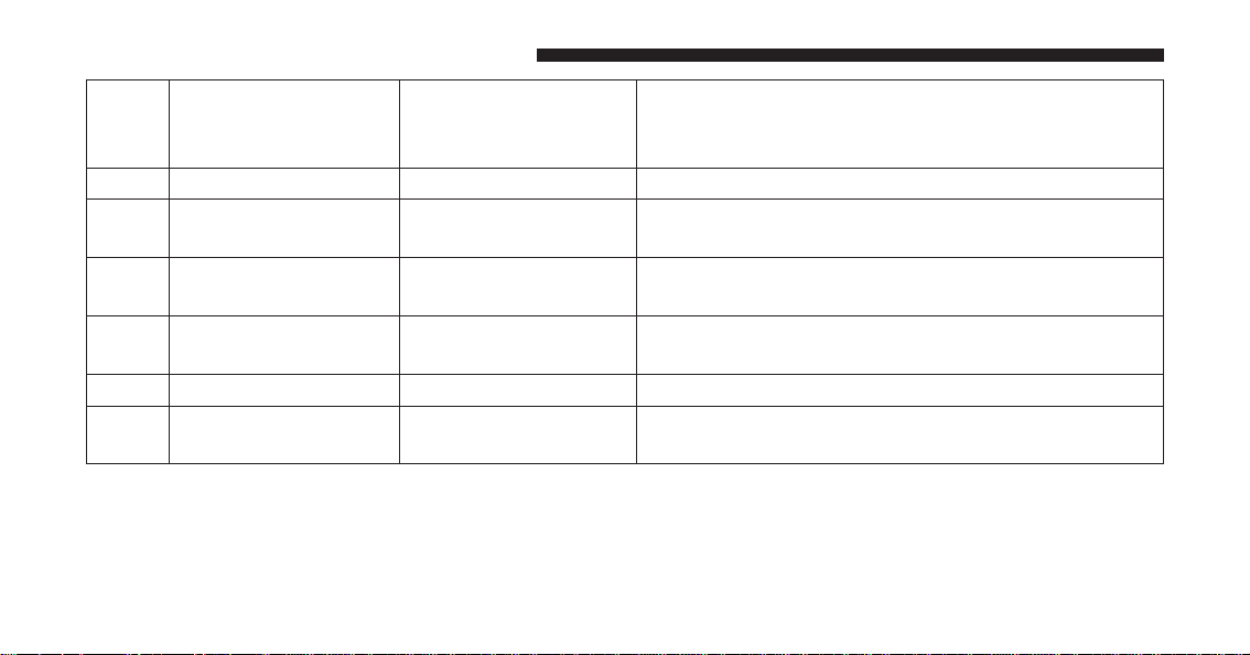
Setting Names
Setting Names Ab-
breviated (Left Sub-
menu Layer)
Sub-Menus (Right Submenu Layer)
28 Transport Mode Transport Mode On; Off
29 Wheel Alignment
Mode
Wheel Alignment On; Off
30 Horn w/ Remote
Lower
Horn w/ Rmt Lwr On; Off
31 Lights w/ Remote
Lower
Lights w/ Rmt Lwr On; Off
32 Trailer Select Trailer Select Trailer 1; Trailer 2; Trailer 3; Trailer 4
33 Brake Type Brake Type Light Electric; Heavy Electric; Light EOH; Heavy
EOH
326 UNDERSTANDING YOUR INSTRUMENT PANEL

Setting Names
Setting Names Ab-
breviated (Left Sub-
menu Layer)
Sub-Menus (Right Submenu Layer)
34 Trailer Name Trailer Name
• Trailer # (# is equal to slot position)
• Boat
• Car
• Cargo
• Dump
• Equipment
• Flatbed
• Gooseneck
• Horse
• Livestock
• Motorcycle
• Snowmobile
• Travel
• Utility
• 5th Wheel
4
UNDERSTANDING YOUR INSTRUMENT PANEL 327
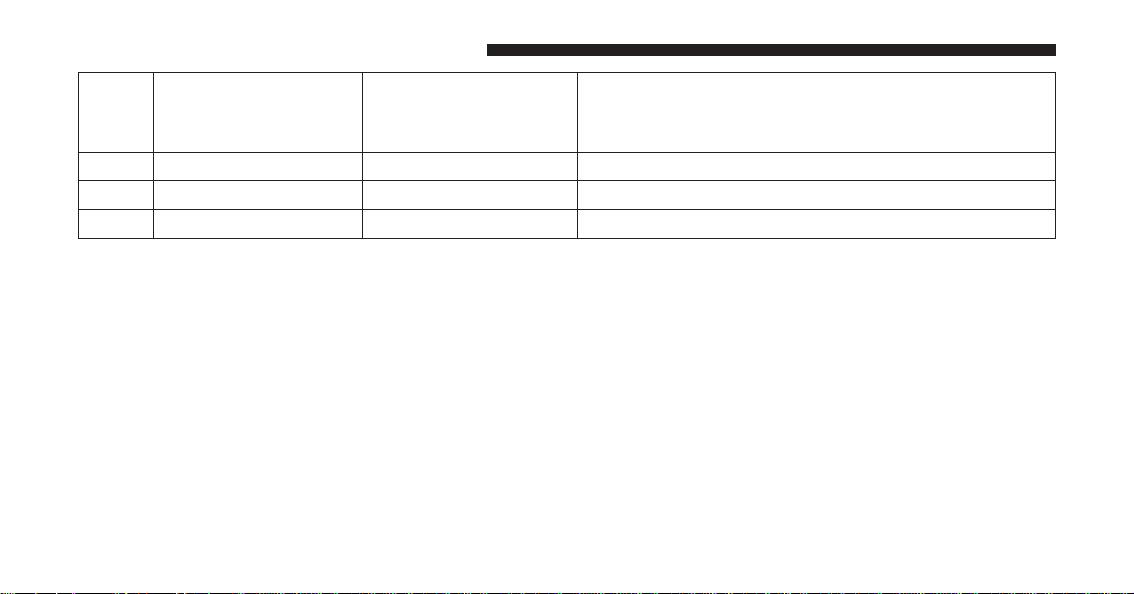
Setting Names
Setting Names Ab-
breviated (Left Sub-
menu Layer)
Sub-Menus (Right Submenu Layer)
35 Compass Variance Compass Var 1-15 increments of 1
36 Calibrate Compass Compass Cal Cancel; Calibrate
37 Fuel Saver Display Fuel Saver On; Off
Turn Menu OFF
Push and release the RIGHT arrow button to exit the
main menu.
Push and release any EVIC control button to enter the
EVIC main menu again.
DRIVER INFORMATION DISPLAY (DID)
The Driver Information Display (DID) features a driver-
interactive display that is located in the instrument
cluster.
328 UNDERSTANDING YOUR INSTRUMENT PANEL

The DID Menu items consists of the following:
• Digital Speedometer
• Vehicle Info
• Fuel Economy Info
• Trip A
• Trip B
• Stop/Start Info (If Equipped)
• Trailer Tow
• Audio
• Stored Messages
• Screen Setup
• Vehicle Settings (Not Equipped with a Uconnect 5.0 &
8.4 radio)
Driver Information Display (DID)
4
UNDERSTANDING YOUR INSTRUMENT PANEL 329

The system allows the driver to select information by pushing
the following buttons mounted on the steering wheel:
• UP Arrow Button
Push and release the UP arrow button to scroll
upward through the main menu and submenus.
• DOWN Arrow Button
Push and release the DOWN arrow button to
scroll downward through the main menu and
submenus.
• RIGHT Arrow Button
Push and release the RIGHT arrow button to
access/select the information screens or sub-
menu screens of a main menu item. Push and
hold the RIGHT arrow button for two seconds
to reset displayed/selected features that can be reset.
• LEFT Arrow Button
Push and release the LEFT arrow button to
return to the main menu from an info screen or
submenu item.
DID Controls
330 UNDERSTANDING YOUR INSTRUMENT PANEL

Driver Information Display (DID) Displays
The DID displays are located in the center portion of the
cluster and consists of eight sections:
1. Main Screen — The inner ring of the display will
illuminate in grey under normal conditions, yellow for
non critical warnings, red for critical warnings, and
white for on demand information.
2. Audio / Phone Information and Sub-menu Informa-
tion — Whenever there are sub-menus available, the
position within the sub-menus is shown here.
3. Selectable Information (Compass, Temp, Range to
Empty, Trip A, Trip B, Average MPG, Trailer Trip
(distance only), Trailer Brake Gain, Time)
4. Telltales/Indicators
5. Shift Lever Status (PRNDL)
6. Selectable Menu Icons
7. Air Suspension Status – If Equipped
8. 4WD Status
4
UNDERSTANDING YOUR INSTRUMENT PANEL 331

9. Selectable Gauge 2 (Trans Temp, Oil Temp, Oil Life,
Trailer Brake, Current MPG)
10. Selectable Gauge 1 (Trans Temp, Oil Temp, Oil Life,
Trailer Brake, Current MPG)
The main display area will normally display the main
menu or the screens of a selected feature of the main
menu. The main display area also displays “pop up”
messages that consist of approximately 60 possible warn-
ing or information messages. These pop up messages fall
into several categories:
• Five Second Stored Messages
When the appropriate conditions occur, this type of
message takes control of the main display area for five
seconds and then returns to the previous screen. Most of
the messages of this type are then stored (as long as the
condition that activated it remains active) and can be
reviewed from the “Messages” main menu item. As long
as there is a stored message, an “i” will be displayed in
the DID’s compass/outside temp line. Examples of this
message type are “Right Front Turn Signal Lamp Out”
and “Low Tire Pressure.”
• Unstored Messages
This message type is displayed indefinitely or until the
condition that activated the message is cleared. Examples
of this message type are “Turn Signal On” (if a turn signal
is left on) and “Lights On” (if driver leaves the vehicle).
• Unstored Messages Until RUN
These messages deal primarily with the Remote Start
feature. This message type is displayed until the ignition
is in the RUN state. Examples of this message type are
“Remote Start Aborted - Door Ajar” and “Press Brake
Pedal and Push Button to Start.”
• Five Second Unstored Messages
When the appropriate conditions occur, this type of
message takes control of the main display area for five
332 UNDERSTANDING YOUR INSTRUMENT PANEL

seconds and then returns to the previous screen. An
example of this message type is “Automatic High Beams
On.”
Oil Life Reset
Your vehicle is equipped with an engine oil change
indicator system. The “Oil Change Required” message
will flash in the DID display for approximately 10
seconds after a single chime has sounded, to indicate the
next scheduled oil change interval. The engine oil change
indicator system is duty cycle based, which means the
engine oil change interval may fluctuate, dependent
upon your personal driving style.
NOTE: Use the steering wheel DID controls for the
following procedure(s).
Vehicles Equipped With Passive Entry
1. Without pushing the brake pedal, push the ENGINE
START/STOP button and cycle the ignition to the
ON/RUN position (do not start the engine).
2. Push and release the DOWN arrow button to scroll
downward through the main menu to “ Vehicle Info.”
3. Push and release the RIGHT arrow button to access
the “ Oil Life” screen.
4. Push and hold the RIGHT arrow button for one
second to access the “ Oil Life Reset” screen.
5. Push and release the DOWN arrow button to select “
Yes,” then push and release the RIGHT arrow button
to select reset of the Oil Life.
6. Push and release the Up arrow button to exit the DID
screen.
4
UNDERSTANDING YOUR INSTRUMENT PANEL 333

Vehicles Not Equipped With Passive Entry
1. Without pushing the brake pedal, cycle the ignition to
the ON/RUN position (do not start the engine).
2. Push and release the DOWN arrow button to scroll
downward through the main menu to “ Vehicle Info.”
3. Push and release the RIGHT arrow button to access
the “ Oil Life” screen.
4. Push and hold the RIGHT arrow button for one
second to access the “ Oil Life Reset” screen.
5. Push and release the DOWN arrow button to select “
Yes,” then push and release the RIGHT arrow button
to select reset of the Oil Life.
6. Push and release the Up arrow button to exit the DID
screen.
NOTE: If the indicator message illuminates when you
start the vehicle, the oil change indicator system did not
reset. If necessary, repeat this procedure.
DID Messages
• Front Seatbelts Unbuckled
• Driver Seatbelt Unbuckled
• Passenger Seatbelt Unbuckled
• Service Airbag System
• Traction Control Off
• Washer Fluid Low
• Oil Pressure Low
• Oil Change Due
• Fuel Low
• Service Antilock Brake System
334 UNDERSTANDING YOUR INSTRUMENT PANEL

• Service Electronic Throttle Control
• Service Power Steering
• Cruise Off
• Cruise Ready
• Cruise Set To XXX MPH
• Tire Pressure Screen With Low Tire(s) “Inflate Tire to
XX”
• Tire Pressure Information System (TPIS)
• Service Tire Pressure System
• Parking Brake Engaged
• Brake Fluid Low
• Service Electronic Braking System
• Engine Temperature Hot
• Battery Voltage Low
• Service Electronic Throttle Control
• Lights On
• Right Turn Signal Light Out
• Left Turn Signal Light Out
• Turn Signal On
• Sound Horn with Remote Lock: Off; 1st Push; 2nd
Push
• Vehicle Not in Park
• Key in Ignition
• Key in Ignition Lights On
• Remote Start Active Key to Run
• Remote Start Active Push Start Button
4
UNDERSTANDING YOUR INSTRUMENT PANEL 335

• Remote Start Aborted Fuel Low
• Remote Start Aborted Too Cold
• Remote Start Aborted Door Open
• Remote Start Aborted Hood Open
• Remote Start Aborted Trunk Open
• Remote Start Aborted Time Expired
• Remote Start Disabled Start to Reset
• Service Airbag System
• Service Airbag Warning Light
• Driver Seatbelt Unbuckled
• Passenger Seatbelt Unbuckled
• Front Seatbelts Unbuckled
• Door Open
• Doors Open
• Gear Not Available
• Shift Not Allowed
• Shift to Neutral then Drive or Reverse
• Autostick Unavailable Service Required
• Automatic Unavailable Use Autostick Service Req.
• Transmission Getting Hot Push Brake
• Trans. Hot Stop Safely Shift to Park Wait to Cool
• Transmission Cool Ready to Drive
• Trailer Brake Disconnected
• Service Transmission
• Service Shifter
• Engage Park Brake to Prevent Rolling
336 UNDERSTANDING YOUR INSTRUMENT PANEL

• Transmission Too cold Idle with Engine On
• Washer Fluid Low
• Service Air Suspension System
• Heavy Duty Air Suspension System Disabled
• Selected Ride Height Not Permitted Due To Speed
• Selected Ride Height Not Permitted Due To Payload
• Selected Ride Height Not Permitted - Payload Too
Light
• Battery Low Start Engine To Change Ride Height
• Normal Ride Height Achieved
• Aerodynamic Ride Height Achieved
• Off Road 1 Ride Height Achieved
• Off Road 2 Ride Height Achieved
• Entry/Exit Ride Height Achieved
• Selected Ride Height Not Permitted
• Service Air Suspension System Immediately
• Reduce Speed To Maintain Selected Ride Height
• Air Suspension System Cooling Down Please Wait
• Vehicle Cannot Be Lowered Door Open
• Off Road 2 Watch For Clearance
• Entry/Exit Watch For Clearance
• Air Suspension Temporarily Disabled For Jacking And
Tire Change
• Battery Low Start Engine To Change Ride Height
• Stop/Start Ready – If Equipped
• Stop/Start Not Ready – If Equipped
4
UNDERSTANDING YOUR INSTRUMENT PANEL 337

• Stop/Start Not Ready Hood Open – If Equipped
• Stop/Start Not Ready Battery Charging – If Equipped
• Stop/Start Not Ready Trailer Tow/Haul Selected – If
Equipped
• Stop/Start Not Ready 4WD/Low Range Selected – If
Equipped
• Stop/Start Not Ready Fuel Level Low – If Equipped
• Stop/Start Not Ready Steep Incline – If Equipped
• Stop/Start Not Ready Extreme Outside Temperature –
If Equipped
• Stop/Start Not Ready Engine Temperature Too High –
If Equipped
• Stop/Start Not Ready Engine Temperature Too Low –
If Equipped
• Stop/Start Not Ready Driver Seatbelt Unbuckled – If
Equipped
• Stop/Start Not Ready Driver Door Open – If Equipped
• Stop/Start Not Ready Cabin Cooling Or Heating – If
Equipped
• Stop/Start Not Ready Not Ready Max Cooling Or
Heating – If Equipped
• Stop/Start Not Ready Max Cooling Or Heating Se-
lected – If Equipped
• Stop/Start Not Ready Front Defrost Selected – If
Equipped
• Stop/Start Not Ready Steering Wheel Turned – If
Equipped
• Stop/Start Autostop Active – If Equipped
338 UNDERSTANDING YOUR INSTRUMENT PANEL
• Stop/Start To Restart Push Clutch Or Shift To Neutral
– If Equipped
• Stop/Start Req’d Fault Detected – If Equipped
• Stop/Start Cannot Autostart Hood Open – If
Equipped
• Stop/Start Unavailable Service Battery – If Equipped
• Stop/Start Unavailable Service Stop/Start System – If
Equipped
• Stop/Start To Restart Shift Out Of Park – If Equipped
• Stop/Start Off – If Equipped
• Autostop Duration – If Equipped
The Reconfigurable Telltales section is divided into the
white telltales area on the right, yellow telltales in the
middle, and red telltales on the left.
DID Red Telltales
This area will show reconfigurable red telltales. These
telltales include:
• Door Ajar
This light will turn on to indicate that one or
more doors may be ajar.
• Oil Pressure Warning Light
This telltale indicates low engine oil pressure. If
the light turns on while driving, stop the vehicle and shut
off the engine as soon as possible. A chime will sound
when this light turns on.
Do not operate the vehicle until the cause is corrected.
This light does not show how much oil is in the engine.
The engine oil level must be checked under the hood.
4
UNDERSTANDING YOUR INSTRUMENT PANEL 339

• Oil Temperature Warning Light
This telltale indicates engine oil temperature is
high. If the light turns on while driving, stop
the vehicle and shut off the engine as soon as
possible.
• Charging System Light
This light shows the status of the electrical charg-
ing system. If the light stays on or comes on while
driving, turn off some of the vehicle’s non-essential
electrical devices or increase engine speed (if at idle). If
the charging system light remains on, it means that the
vehicle is experiencing a problem with the charging
system. OBTAIN SERVICE IMMEDIATELY. See an au-
thorized dealer.
Refer to “Jump Starting Procedures” in “What To Do In
Emergencies” if jump starting is required.
• Electronic Throttle Control (ETC) Light
This light informs you of a problem with the
Electronic Throttle Control (ETC) system. The
light will come on when the ignition is first
turned ON and remain on briefly as a bulb
check. If the light does not come on during starting, have
the system checked by an authorized dealer.
If a problem is detected, the light will come on while the
engine is running. Cycle the ignition key when the
vehicle has completely stopped and the shift lever is
placed in the PARK position. The light should turn off.
If the light remains lit with the engine running, your
vehicle will usually be drivable. However, see an autho-
rized dealer for service as soon as possible. If the light is
flashing when the engine is running, immediate service is
required. You may experience reduced performance, an
elevated/rough idle or engine stall and your vehicle may
require towing.
340 UNDERSTANDING YOUR INSTRUMENT PANEL
• Engine Temperature Warning Light
This light warns of an overheated engine condi-
tion. As temperatures rise and the gauge ap-
proaches H, this indicator will illuminate and a single
chime will sound after reaching a set threshold. Further
overheating will cause the temperature gauge to pass H,
a continuous chime will occur until the engine is allowed
to cool.
If the light turns on while driving, safely pull over and
stop the vehicle. If the A/C system is on, turn it off. Also,
shift the transmission into NEUTRAL and idle the ve-
hicle. If the temperature reading does not return to
normal, turn the engine off immediately and call for
service. Refer to “If Your Engine Overheats” in “What To
Do In Emergencies” for further information.
NOTE: When the transmission is shifted to Neutral,
activate the parking brake to prevent the vehicle from
rolling away.
• Electric Power Steering Malfunction Warning Light
This telltale is on when the Electric Power
Steering is not operating and needs service.
• Trailer Brake Disconnected Warning Light
This telltale is on when the Trailer Brake has
been disconnected.
DID Yellow Telltales
This area will show reconfigurable yellow caution tell-
tales. These telltales include:
• Low Fuel Telltale
When the fuel level reaches approximately 3.0 gal
(11.0 L), this light will turn on, and remain on until
fuel is added.
4
UNDERSTANDING YOUR INSTRUMENT PANEL 341
• Windshield Washer Fluid Low Indicator
This telltale will turn on to indicate the wind-
shield washer fluid is low.
• Low Coolant Level Indicator
This telltale will turn on to indicate the vehicle
coolant level is low.
• Transmission Temperature Warning Telltale
This telltale indicates that the transmission
fluid temperature is running hot. This may
occur with severe usage, such as trailer towing.
If this telltale turns on, safely pull over and
stop the vehicle. Then, shift the transmission into NEU-
TRAL and run the engine at idle or faster until the light
turns off.
CAUTION!
Continuous driving with the Transmission Tempera-
ture Warning Light illuminated will eventually cause
severe transmission damage or transmission failure.
WARNING!
If you continue operating the vehicle when the
Transmission Temperature Warning Light is illumi-
nated you could cause the fluid to boil over, come in
contact with hot engine or exhaust components and
cause a fire.
342 UNDERSTANDING YOUR INSTRUMENT PANEL
• Air Suspension Payload Protection Telltale — If
Equipped
This telltale will turn on to indicate that the
maximum payload may have been exceeded or
load leveling cannot be achieved at its current
ride height.
Protection Mode will automatically be selected in order
to “protect” the air suspension system, air suspension
adjustment is limited due to payload.
• Service Stop/Start System Telltale — If Equipped
This telltale will turn on to indicate that the
Stop/Start is Unavailable, service Stop/Start
system.
• Loose Fuel Filler Cap
This telltale will turn on to indicate that the fuel
filler cap may be loose.
DID White Telltales
• Electronic Speed Control Ready
This light will turn on when the electronic
speed control is ON. Refer to “Electronic Speed
Control” in “Understanding The Features Of
Your Vehicle” for further information.
• Electronic Speed Control SET
This light will turn on when the electronic
speed control is SET. Refer to “Electronic Speed
Control” in “Understanding The Features Of
Your Vehicle” for further information.
4
UNDERSTANDING YOUR INSTRUMENT PANEL 343

• Hill Descent Control – If equipped
This indicator will illuminate when Hill De-
scent Control (HDC) has been selected using
the Hill Descent Control Switch. Refer to “Elec-
tronic Brake Control” in “Starting And Operat-
ing” for further information.
DID Selectable Menu Items
Push and release the UP or DOWN arrow buttons until
the desired Selectable Menu icon/title is highlighted in
the DID.
Digital Speedometer
Push and release the UP or DOWN arrow
button until the Digital display icon is high-
lighted in the DID. Push and release the
RIGHT arrow button to change the display
between mph and km/h.
Vehicle Info
Push and release the UP or DOWN arrow
button until the Vehicle Info icon is highlighted
in the DID. Push and release the RIGHT arrow
button to enter the submenus items of Vehicle
Info. follow the directional prompts to access or reset any
of the following Vehicle Info submenu items:
Tire Pressure Monitoring System (1500 & 2500 Series)
A vehicle ICON is displayed with tire pressure values in
each corner of the ICON.
• Tire Pressure:
– Tire Pressure Information System (3500 Series
Heavy Duty Ram Trucks)
– A vehicle ICON is displayed with the tire pressure
values in each corner of the ICON.
344 UNDERSTANDING YOUR INSTRUMENT PANEL

– If the Tire Pressure system requires service, “Service
Tire Pressure System” is displayed.
– Tire Pressure is an information only function and
cannot be reset.
– Refer to the ⬙Tire Pressure Information System
(TPIS)” under ⬙Starting and Operating⬙ for further
information.
• Transmission Temperature – Automatic Transmission
Only
• Oil Temperature
• Oil Life
• Battery Voltage — If Equipped
• Gauge Summary:
– Coolant Temperature
– Transmission Temperature (automatic only)
– Oil Temperature
– Oil Pressure
• Engine Hours
Fuel Economy
Push and release the UP or DOWN arrow
button until the Fuel Economy Menu icon/title
is highlighted. Push and hold the OK button to
reset feature.
• Range
• Current MPG or L/100 km
• Average MPG or L/100 km
4
UNDERSTANDING YOUR INSTRUMENT PANEL 345

Trip A
Push and release the UP or DOWN arrow
button until the Trip A icon/title is highlighted
in the DID. The Trip A information will display
the following:
• Distance MI or km
• Average MPG or L/100 km
• Average MPH or km/h
• Elapsed Time
Hold the RIGHT arrow button to reset all the informa-
tion.
Push the DOWN arrow button to enter Trip B.
Trip B
The Trip B information will display the
following:
• Distance MI or km
• Average MPG or L/100 km
• Average MPH or km/h
• Elapsed Time
Hold the RIGHT arrow button to reset all the informa-
tion.
346 UNDERSTANDING YOUR INSTRUMENT PANEL

Stop/Start – If Equipped
Push and release the UP or DOWN arrow
button until the Stop/Start icon is highlighted
in the DID. Push and release the RIGHT arrow
button to display the Stop/Start status.
Trailer Tow
Push and release the UP or DOWN arrow
button until the Trailer Tow icon is highlighted.
Push and release the RIGHT arrow button and
the next screen will display the following
trailer trip information:
• Trailer Trip
• Trailer Brake
Audio
Push and release the UP or DOWN arrow
button until the Audio display icon is high-
lighted in the DID. Push and release the
RIGHT arrow button to display the active
source.
Stored Messages
Push and release the UP arrow button until the
Messages display icon is highlighted in the
DID. This feature shows the number of stored
warning messages. Pushing the RIGHT arrow
button will allow you to see what the stored messages
are.
4
UNDERSTANDING YOUR INSTRUMENT PANEL 347
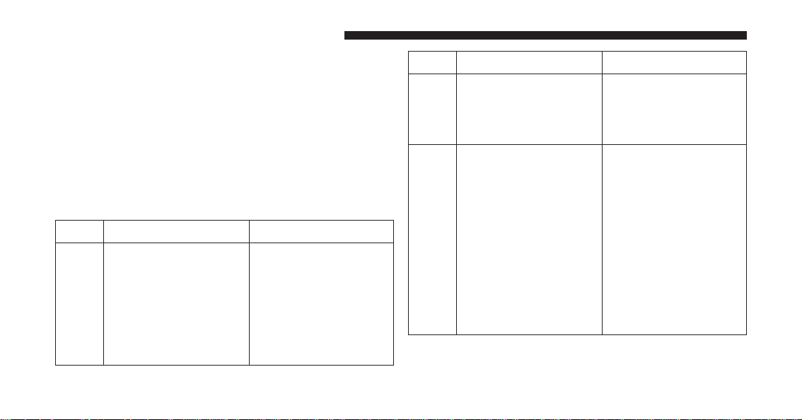
Screen Setup
Push and release the UP or DOWN arrow
button until the Screen Setup display icon is
highlighted in the DID. Push and release the
RIGHT arrow button to enter the Screen Setup
submenu. The Screen Setup feature allows you to change
what information is displayed in the instrument cluster
as well as the location that information is displayed.
Settings Options
1 Upper Left
• None
• Compass
• Outside Temp.
• Time
• Range
• Average MPG
• Current MPG
Settings Options
• Trip A
• Trip B
• Trailer Trip
• Trailer Brake Gain
2 Upper Right
• None
• Compass
• Outside Temp.
• Time
• Range
• Average MPG
• Current MPG
• Trip A
• Trip B
• Trailer Trip
• Trailer Brake Gain
348 UNDERSTANDING YOUR INSTRUMENT PANEL
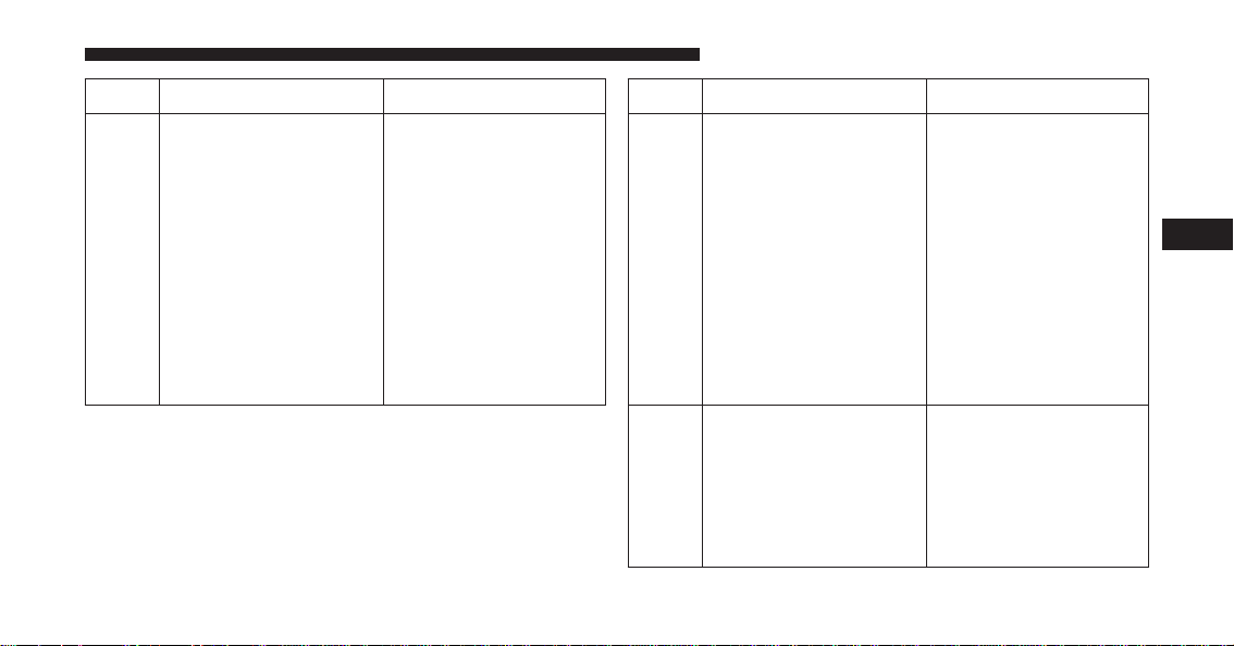
Settings Options
3 Lower Left
• None
• Compass
• Outside Temp.
• Time
• Range
• Average MPG
• Current MPG
• Trip A
• Trip B
• Trailer Trip
• Trailer Brake Gain
Settings Options
4 Lower Right
• None
• Compass
• Outside Temp.
• Time
• Range
• Average MPG
• Current MPG
• Trip A
• Trip B
• Trailer Trip
• Trailer Brake Gain
5 Upper Gauge
• None
• Trans Temp.
• Oil Temp.
• Oil Life
• Current MPG
• Trailer Brake Gain
4
UNDERSTANDING YOUR INSTRUMENT PANEL 349

Settings Options
6 Lower Gauge
• None
• Trans Temp.
• Oil Temp.
• Oil Life
• Current MPG
• Trailer Brake Gain
7 Odometer
• 000
• 000.0
8 Restore Defaults
• Cancel
• OK
Vehicles Settings (Customer-Programmable
Features)
NOTE: This feature is only available on 5.0 and
8.4 Uconnect® Radios
Personal Settings allows the driver to set and
recall features when the transmission is in PARK.
Push and release the UP and DOWN button until Per-
sonal Settings displays in the DID.
Follow the prompts to display and set any of the follow-
ing Personal Settings.
NOTE: Your vehicle may or may not be equipped with
all the following settings.
350 UNDERSTANDING YOUR INSTRUMENT PANEL
Setting Names
Setting Names Abbreviated
(Left Submenu Layer)
Sub-Menus (Right Submenu
Layer)
1 Language Select Language English, Spanish, French, Italian,
German, Dutch
2 Units Units U.S.; Metric
3 ParkSense ParkSense
• Notification — Sound Only;
Sound & Display
• Front Volume — Low; Me-
dium; High
• Rear Volume — Low; Me-
dium; High
4 Tilt Mirror in Reverse Tilt Mirror in R On; Off
5 Rain Sensing Wipers Auto Wipers On; Off
6 Hill Start Assist Hill Start Assist On; Off
7 Headlights Off Delay Lights Off Delay 0 seconds; 30 seconds; 60 sec-
onds; 90 seconds
4
UNDERSTANDING YOUR INSTRUMENT PANEL 351
Setting Names
Setting Names Abbreviated
(Left Submenu Layer)
Sub-Menus (Right Submenu
Layer)
8 Illuminated Approach Lights w/ Unlock 0 seconds; 30 seconds; 60 sec-
onds; 90 seconds
9 Headlights On with Wipers Lights w/ Wipers On; Off
10 Automatic Highbeams Auto Highbeams On; Off
11 Flash Lights with Lock Lights w/ Lock On; Off
12 Auto Lock Doors Auto Lock Doors On; Off
13 Auto Unlock Doors Auto Unlock Doors On; Off
14 Sound Horn with Remote Start Horn w/ Rmt Start On; Off
15 Sound Horn with Remote Lock Horn w/ Rmt Lock On; Off
16 Remote Unlock Sequence Remote Unlock Driver Door; All Doors
17 Key Fob Linked to Memory Key in Memory On; Off
18 Passive Entry Passive Entry On; Off
19 Remote Start Comfort System Rmt Start Comfort On; Off
20 Easy Exit Seat Easy Exit Seat On; Off
352 UNDERSTANDING YOUR INSTRUMENT PANEL
Setting Names
Setting Names Abbreviated
(Left Submenu Layer)
Sub-Menus (Right Submenu
Layer)
21 Key-off Power Delay Power Off Delay Off; 45 seconds; 5 minutes; 10
minutes
22 Commercial Settings Commercial
• Aux Switches
• Power Take-Off
• PIN Setup
23 Air Suspension Display Alerts Air Susp. Alerts All; Warnings Only
24 Aero Ride Height Mode Aero Mode On; Off
25 Tire/Jack Mode Tire/Jack Mode On; Off
26 Transport Mode Transport Mode On; Off
27 Wheel Alignment Mode Wheel Alignment On; Off
28 Horn w/ Remote Lower Horn w/ Rmt Lwr On; Off
4
UNDERSTANDING YOUR INSTRUMENT PANEL 353
Setting Names
Setting Names Abbreviated
(Left Submenu Layer)
Sub-Menus (Right Submenu
Layer)
29 Lights w/ Remote Lower Lights w/ Rmt Lwr On; Off
30 Trailer Select Trailer Select Trailer 1; Trailer 2; Trailer 3;
Trailer 4
31 Brake Type Brake Type Light Electric; Heavy Electric;
Light EOH; Heavy EOH
354 UNDERSTANDING YOUR INSTRUMENT PANEL

Setting Names
Setting Names Abbreviated
(Left Submenu Layer)
Sub-Menus (Right Submenu
Layer)
32 Trailer Name Trailer Name
• Trailer # (# is equal to slot
position)
• Boat
• Car
• Cargo
• Dump
• Equipment
• Flatbed
• Gooseneck
• Horse
• Tag
• Motorcycle
• Snowmobile
• Travel
• Utility
• 5th Wheel
4
UNDERSTANDING YOUR INSTRUMENT PANEL 355
Setting Names
Setting Names Abbreviated
(Left Submenu Layer)
Sub-Menus (Right Submenu
Layer)
33 Compass Variance Compass Var 1-15 increments of 1
34 Calibrate Compass Compass Cal Cancel; Calibrate
35 Fuel Saver Display Fuel Saver On; Off
36 Park Assist Front Chime Vol-
ume
Park Assist Front Chime Vol-
ume
On; Off
37 Park Assist Rear Chime Volume Park Assist Rear Chime Volume On; Off
Uconnect® SETTINGS
The Uconnect® system uses a combination of buttons on
the touchscreen and buttons on the faceplate located on
the center of the instrument panel that allows you to
access and change the customer programmable features.
Many features can vary by vehicle.
356 UNDERSTANDING YOUR INSTRUMENT PANEL

Uconnect® 5.0 Buttons On The Touchscreen And Buttons
On The Faceplate
1 — Uconnect® Buttons On The Touchscreen
2 — Uconnect® Buttons On The Faceplate
Uconnect® 8.4A/8.4AN Buttons On The Touchscreen And
Buttons On The Faceplate
1 — Uconnect® Buttons On The Touchscreen
2 — Uconnect® Buttons On The Faceplate
4
UNDERSTANDING YOUR INSTRUMENT PANEL 357

Buttons On The Faceplate
Buttons on the faceplate are located below the Uconnect®
system in the center of the instrument panel. In addition,
there is a Scroll/Enter control knob located on the right
side of the Climate Controls in the center of the instru-
ment panel. Turn the control knob to scroll through
menus and change settings (i.e., 30, 60, 90), push the
center of the control knob one or more times to select or
change a setting (i.e., ON, OFF).
Your Uconnect® system may also have Screen Off and
Back buttons located below the Uconnect® system.
Push the Screen Off button to turn off the Uconnect®
touchscreen. Push the Screen Off button a second time to
turn the touchscreen on.
Push the Back button to exit out of a Menu or certain
option on the Uconnect® system.
Buttons On The Touchscreen
Buttons on the touchscreen are accessible on the
Uconnect® display.
Customer Programmable Features — Uconnect®
5.0 Personal Settings
Push the Settings button on the faceplate to display the
settings menu screen. In this mode the Uconnect® system
allows you to access programmable features that may be
equipped such as Display, Voice, Clock, Safety & Assis-
tance, Lights, Doors & Locks, Auto-On Comfort (if
equipped), Engine Off Options, Suspension, Trailer
Brake, Audio, Compass Settings, Phone/Bluetooth®,
SiriusXM Setup (if equipped), Restore Settings, Clear
Personal Data and System Information.
NOTE: Only one category may be selected at a time.
358 UNDERSTANDING YOUR INSTRUMENT PANEL

When making a selection, press the button on the touch-
screen to enter the desired mode. Once in the desired
mode, press and release the preferred setting until the
button is highlighted. Once the setting is complete, either
press the back arrow or Done button on the touchscreen
or the Back button on the faceplate to return to the
previous menu. Pressing the Up or Down Arrow buttons
on the touchscreen on the right side of the screen will
allow you to toggle up or down through the list of
available settings.
NOTE: All settings should be changed with the ignition
in the “Run” position.
Display
After pressing the “Display” button on the touchscreen
the following settings will be available.
• Display Mode
When in this display you may select the Auto or Manual
display settings. To change Mode status, press and re-
lease the “Auto” or “Manual” button on the touchscreen.
Press the back arrow/Done button on the touchscreen to
return to the previous menu.
• Set Language
When in this display, you may select one of multiple
languages (English/Français/Español) for all display no-
menclature, including the trip functions and the naviga-
tion system (if equipped). Press the “Language” button
on the touchscreen and select from “English,” “Français,”
or “Español.” Press the back arrow/Done button on the
touchscreen to return to the previous menu.
• Units
When in this display, you may select to have the EVIC/
DID, odometer, and navigation system (if equipped)
4
UNDERSTANDING YOUR INSTRUMENT PANEL 359

changed between US and Metric units of measure. Press
“US” or “Metric” to make your selection. Press the back
arrow/Done button on the touchscreen to return to the
previous menu.
• Touchscreen Beep
When in this display, you may turn on or shut off the
sound heard when a touchscreen button is pressed. To
change the Mode status, press and release the “On” or
“Off” button on the touchscreen. Press the back arrow/
Done button on the touchscreen to return to the previous
menu
• Fuel Saver Display — If Equipped
This feature will allow you to enable fuel saver mode and
will be displayed in the EVIC/DID. Press the “Fuel Saver
Display” button on the touchscreen select from “On” or
“Off.” Press the back arrow/Done button on the touch-
screen to return to the previous menu.
Voice
After pressing the “Voice” button on the touchscreen the
following settings will be available:
• Voice Response Length
When in this display, you may change the Voice Re-
sponse Length settings. To change the Voice Response
Length, press the “Voice Response Length” button on the
touchscreen and select from “Brief” or “Detailed.” Press
the back arrow/Done button on the touchscreen to return
to the previous menu.
• Show Command List
When in this display, you may change the Show Com-
mand List settings. To change the Show Command List
settings, press the “Show Command List” button on the
touchscreen and select from “Always,” “With Help” or
“Never.” Press the back arrow/Done button on the
touchscreen to return to the previous menu.
360 UNDERSTANDING YOUR INSTRUMENT PANEL

Clock & Date
After pressing the “Clock & Date” button on the touch-
screen the following settings will be available:
• Set Time
When in this display, you may set the time and format
manually. Press the “Set Time” button then choose from
a “12 hour” or “24 hour format.” Press the corresponding
arrow above and below the current time to adjust, then
select “AM” or “PM.” Press the back arrow/Done button
on the touchscreen to return to the previous menu.
• Set Date
When in this display, you may set the date manually.
Press the “Set Date” button then press the corresponding
arrows above and below the current date to adjust. Press
the back arrow/Done button on the touchscreen to return
to the previous menu.
Safety/Assistance
After pressing the “Safety/Assistance” button on the
touchscreen the following settings will be available:
• ParkSense®
The ParkSense® system will scan for objects behind the
vehicle when the transmission shift lever/gear selector is
in REVERSE and the vehicle speed is less than 11 mph (18
km/h). It will provide an alert (audible and/or visual) to
indicate the proximity to other objects. The system can be
enabled with Sound Only, or Sound and Display. To
change the ParkSense® status, press and release the
“Sound Only” or “Sounds and Display” button. Then
press the back arrow/Done button on the touchscreen.
Refer to “ParkSense®” in “Understanding The Features
Of Your Vehicle” for system function and operating
information.
4
UNDERSTANDING YOUR INSTRUMENT PANEL 361

• Tilt Mirrors In Reverse — If Equipped
When this feature is selected, the exterior sideview
mirrors will tilt downward when the ignition is in the
RUN position and the transmission shift lever/gear
selector is in the REVERSE position. The mirrors will
move back to their previous position when the transmis-
sion is shifted out of REVERSE. To make your selection,
press the “Tilt Mirrors In Reverse” button on the touch-
screen and make your selection. Press the back arrow/
Done button on the touchscreen to return to the previous
menu.
• ParkView® Backup Camera Active Guidelines
Your vehicle may be equipped with the ParkView® Rear
Back Up Camera Active Guidelines that allows you to see
active guidelines over the ParkView Back up camera
display whenever the shift lever/gear selector is put into
REVERSE. The image will be displayed on the radio
touchscreen display along with a caution note to “check
entire surroundings” across the top of the screen. After
five seconds, this note will disappear. To make your
selection, press the “ParkView® Backup Camera Active
Guidelines” button on the touchscreen and make your
selection. Press arrow button on the touchscreen to return
to the previous menu.
• ParkView® Backup Camera Delay
When the vehicle is shifted out of REVERSE (with camera
delay turned OFF), the rear camera mode is exited and
the navigation or audio screen appears again. When the
vehicle is shifted out of REVERSE (with camera delay
turned ON), the rear view image with dynamic grid lines
will be displayed for up to 10 seconds after shifting out of
“REVERSE” unless the forward vehicle speed exceeds
8 mph (12 km/h), the transmission is shifted into PARK
or the ignition is switched to the OFF position. To set the
ParkView® Backup Camera Delay push the SETTINGS
button on the faceplate, then the “Safety & Driving
362 UNDERSTANDING YOUR INSTRUMENT PANEL

Assistance” button on the touchscreen. Press the
“Parkview Backup camera Delay” button on the touch-
screen to turn the ParkView® Delay ON or OFF.
• Rain Sensing Auto Wipers
When this feature is selected, the system will automati-
cally activate the windshield wipers if it senses moisture
on the windshield. To make your selection, press the
“Rain Sensing” button on the touchscreen and make your
selection. Press the back arrow/Done button on the
touchscreen to return to the previous menu.
• Hill Start Assist — If Equipped
When this feature is selected, the Hill Start Assist (HSA)
system is active. Refer to “Electronic Brake Control
System” in “Starting And Operating” for system function
and operating information. To make your selection, press
the “Hill Start Assist” button on the touchscreen and
make your selection. Press the back arrow/Done button
on the touchscreen to return to the previous menu.
Lights
After pressing the “Lights” button on the touchscreen,
the following settings will be available:
• Headlight Off Delay
When this feature is selected, it allows the adjustment of
the amount of time the headlights remain on after the
engine is shut off. To change the Headlight Off Delay
setting, press the “Headlight Off Delay” button on the
touchscreen and choose either “0,” “30,” “60,” or “90”
buttons on the touchscreen to select your desired time
interval. Press the back arrow/Done button on the touch-
screen to return to the previous menu.
• Headlight Illumination On Approach
When this feature is selected, it allows the adjustment of
the amount of time the headlights remain on when the
doors are unlocked with the Remote Keyless Entry (RKE)
transmitter. To change the Illuminated Approach status,
4
UNDERSTANDING YOUR INSTRUMENT PANEL 363

press the “Illuminated Approach” button on the touch-
screen and choose either “0,” “30,” “60,” or “90” buttons
on the touchscreen to select your desired time interval.
Press the back arrow/Done button on the touchscreen to
return to the previous menu.
• Headlights With Wipers — If Equipped
When this feature is selected, and the headlight switch is
in the AUTO position, the headlights will turn on ap-
proximately 10 seconds after the wipers are turned on.
The headlights will also turn off when the wipers are
turned off, if they were turned on by this feature. To
make your selection, press the “Lights w/Wipers” button
and select from “On” or “Off.” Press the back arrow/
Done button on the touchscreen to return to the previous
menu.
• Auto Dim High Beams — If Equipped
When this feature is selected, the high beam headlights
will activate/deactivate automatically under certain con-
ditions. To make your selection, press the “Auto High
Beams” button on the touchscreen, and select from “On”
or “Off.” Press the back arrow/Done button on the
touchscreen to return to the previous menu. Refer to
”Automatic High Beam — If Equipped” in “Understand-
ing The Features Of Your Vehicle” for further informa-
tion.
• Daytime Running Lights — If Equipped
When this feature is selected, the headlights will turn on
whenever the engine is running. To make your selection,
press the “Daytime Running Lights” button on the touch-
screen, and select from “On” or “Off.” Press the back
arrow/Done button on the touchscreen to return to the
previous menu.
364 UNDERSTANDING YOUR INSTRUMENT PANEL

• Flash Lights With Lock
When this feature is selected, the exterior lights will flash
when the doors are locked or unlocked with the Remote
Keyless Entry (RKE) transmitter. This feature may be
selected with or without the sound horn on lock feature
selected. To make your selection, press the “Flash Lights
w/Lock” button on the touchscreen, and select from
“On” or “Off.” Press the back arrow/Done button on the
touchscreen to return to the previous menu.
Doors & Locks
After pressing the “Doors & Locks” button on the touch-
screen, the following settings will be available:
• Auto Door Locks
When this feature is selected, all doors will lock auto-
matically when the vehicle reaches a speed of 15 mph
(24 km/h). To make your selection, press the “Auto Door
Locks” button on the touchscreen and select from “On”
or “Off.” Press the back arrow/Done button on the
touchscreen to return to the previous menu.
• Auto Unlock On Exit
When this feature is selected, all doors will unlock when
the vehicle is stopped, the transmission is in the PARK or
NEUTRAL position and the driver’s door is opened. To
make your selection, press the “Auto Unlock On Exit”
button on the touchscreen and select from “On” or “Off.”
Press the back arrow/Done button on the touchscreen to
return to the previous menu.
• Sound Horn With Lock
When this feature is selected, the horn will sound when
the door locks are activated. To make your selection,
press the “Horn w/Lock” Button and choose “Off,” “1st
Press” or “2nd Press.” Press the back arrow/Done button
on the touchscreen to return to the previous menu.
4
UNDERSTANDING YOUR INSTRUMENT PANEL 365

• Sound Horn With Remote Start
When this feature is selected, the horn will sound when
the remote start is activated. To make your selection,
press the “Horn w/Remote Start” button on the touch-
screen and select from “On” or “Off.” Press the back
arrow/Done button on the touchscreen to return to the
previous menu.
• Remote Door Unlock
This feature will allow you to program your remote door
locks to open “All doors” or only the “Driver door” with
the first push of the Remote Keyless Entry (RKE) trans-
mitter or grabbing the Passive Entry door handle. To
make your selection, press the “Remote Door Unlock”
button on the touchscreen and choose from “All” or
“Driver.” Press the back arrow/Done button on the
touchscreen to return to the previous menu.
NOTE: If “Driver Door” is selected, the (RKE) transmitter
will have to be pushed two times in order to unlock all
doors.
• Memory Linked to Fob — If Equipped
This feature provides automatic driver seat positioning to
enhance driver mobility when entering and exiting the
vehicle. To make your selection, press the “Memory
Linked to Fob” button on the touchscreen and select from
“On” or “Off.” Press the back arrow/Done button on the
touchscreen to return to the previous menu.
NOTE: The seat will return to the memorized seat
location if “Memory Linked to Fob” is set to (ON) when
the Remote Keyless Entry (RKE) transmitter is used to
unlock the door. Refer to “Driver Memory Seat” in
“Understanding The Features Of Your Vehicle” for fur-
ther information.
366 UNDERSTANDING YOUR INSTRUMENT PANEL

• Passive Entry
This feature allows you to lock and unlock the vehicle’s
door(s) without having to push the Remote Keyless Entry
(RKE) transmitter lock or unlock buttons. It automatically
unlocks the doors when the outside door handle is
grabbed. To make your selection, press the “Passive
Entry” button on the touchscreen and select from “On” or
“Off.” Press the back arrow/Done button on the touch-
screen to return to the previous menu. Refer to “Keyless
Enter-N-Go™” in “Things To Know Before Starting Your
Vehicle” for further information.
• Flash Lights With Lock
When this feature is selected, the exterior lights will flash
when the doors are locked or unlocked with the Remote
Keyless Entry (RKE) transmitter. This feature may be
selected with or without the sound horn on lock feature
selected. To make your selection, press the “Flash Lights
w/Lock” button on the touchscreen, and select from
“On” or “Off.” Press the back arrow/Done button on the
touchscreen to return to the previous menu.
Auto Comfort Systems — If Equipped
After pressing the “Auto-On Comfort” button on the
touchscreen the following settings will be available:
• Auto-On Driver Heated/Ventilated Seat & Steering
Wheel With Vehicle Start — If Equipped
When this feature is selected the driver’s heated seat and
heated steering wheel will automatically turn ON when
temperatures are below 40° F (4.4° C). When tempera-
tures are above 80° F (26.7° C) the driver vented seat will
turn ON. To make your selection, press the “Auto Heated
Seats” button on the touchscreen, then select either “On”
or “Off.” Press the back arrow/Done button on the
touchscreen to return to the previous menu.
4
UNDERSTANDING YOUR INSTRUMENT PANEL 367

Engine Off Options
After pressing the “Engine Off Options” button on the
touchscreen the following settings will be available.
• Easy Exit Seats — If Equipped
When this feature is selected, the Driver’s seat will
automatically move rearward once the engine is shut off.
To make your selection, press the “Easy Exit Seats”
button on the touchscreen and make your selection. Press
the back arrow/Done button on the touchscreen to return
to the previous menu.
• Headlight Off Delay
When this feature is selected, the driver can choose to
have the headlights remain on for 0, 30, 60, or 90 seconds
when exiting the vehicle. Press the “Headlight Off Delay”
button on the touchscreen and choose from “0,” “30,”
“60,” or “90” seconds to select your desired time interval.
Press the back arrow/Done button on the touchscreen to
return to the previous menu.
• Engine Off Power Delay
When this feature is selected, the power window
switches, radio, Uconnect® phone system (if equipped),
DVD video system (if equipped), power sunroof (if
equipped), and power outlets will remain active for up to
10 minutes after the ignition is cycled to OFF. Opening
either front door will cancel this feature. Press the “En-
gine Off Power Delay” button on the touchscreen and
choose from “0 sec,” “45 sec,” “5 min” or “10 min” to
select your desired time interval. Then press the back
arrow/Done button on the touchscreen to return to the
previous menu.
• Auto Entry/Exit — If Equipped
When this feature is selected, it automatically lowers the
vehicle ride height position when shifted into park. Press
the “Auto Entry/Exit” button on the touchscreen and
368 UNDERSTANDING YOUR INSTRUMENT PANEL

choose from “On” or “Off.” Press the back arrow/Done
button on the touchscreen to return to the previous
menu.
Suspension — If Equipped
After pressing the “Suspension” button on the touch-
screen the following settings will be available:
• Sound Horn With Lower
When this feature is selected, a short horn sound will
occur when the RKE transmitter REMOTE LOWER but-
ton is pressed. To make your selection, press the “Horn
w/lower” button on the touchscreen, select “On” or
“Off” followed by pressing the back arrow/Done button
on the touchscreen.
• Flash Lights With Lower
When this feature is selected, the front and rear turn
signals will flash when the RKE transmitter REMOTE
LOWER button is pressed twice. To make your selection,
press the “Light w/Lower” button on the touchscreen,
select “On” or “Off” followed by pressing the back
arrow/Done button on the touchscreen.
• Auto Entry/Exit Suspension
When this feature is selected, the vehicle automatically
lowers from ride height position when vehicle shifted to
park for easy entry/exit. To make your selection, press
the “Auto Entry/Exit” button on the touchscreen, select
“On” or “Off” followed by pressing the back arrow/
Done button on the touchscreen.
• Display Suspension Messages
When “All” is selected, all the Air Suspension Alerts will
be displayed. When “Warning Only” is selected only the
Air Suspension Warnings will be displayed.
• Automatic Aero Mode (1500 Model Only)
When this feature is selected the Ride Height will auto-
matically be adjusted depending on the vehicle speed. To
4
UNDERSTANDING YOUR INSTRUMENT PANEL 369

make your selection, press the “Aero Mode” button on
the touchscreen, select “On” or “Off” followed by press-
ing the back arrow/Done button on the touchscreen.
• Tire Jack Mode
When this feature is selected the air suspension system is
disabled to prevent auto leveling of the suspension, while
the vehicle is on a jack changing a tire. To make your
selection, press the “Tire Jack Mode” button on the
touchscreen, select “On” or “Off” followed by pressing
the back arrow/Done button on the touchscreen.
• Transport Mode
When this feature is selected the air suspension system is
disabled to assist with flat bed towing. To make your
selection, press the “Transport Mode” button on the
touchscreen, select “On” or “Off” followed by pressing
the back arrow/Done button on the touchscreen.
• Wheel Alignment Mode
This feature prevents auto leveling of the air suspension
while performing a wheel alignment service. Before
performing a wheel alignment this mode must be en-
abled. Refer to your authorized dealer for further infor-
mation.
Trailer Brake
After pressing the “Trailer Brake” button on the touch-
screen the following settings will be available:
• Trailer Select
When this feature is selected, the Trailer Type can be
selected between “Trailer 1,” “Trailer 2,” “Trailer 3” and
“Trailer 4.”
• Trailer Brake Type
When this feature is selected, the Trailer Brake Type can
be changed between “Light Electric,” “Heavy Electric,”
370 UNDERSTANDING YOUR INSTRUMENT PANEL

“Light EOH” and “Heavy EOH.” Refer to “Integrated
Trailer Brake Module” in “Starting And Operating.”
Audio
After pressing the “Audio” button on the touchscreen the
following settings will be available:
• Balance/Fade
This feature allows you to adjust the Balance and Fade
settings. Press and drag the speaker icon or use the
arrows to adjust, tap the “C” icon to readjust to the center.
Press the back arrow/Done button on the touchscreen to
return to the previous menu.
• Equalizer
When in this display you may adjust the Bass, Mid and
Treble settings. Adjust the settings with the “+” and “–”
buttons on the touchscreen or by selecting any point on
the scale between the “+” and “–” buttons on the
touchscreen. Press the back arrow/Done button on the
touchscreen to return to the previous menu.
• Speed Adjusted Volume
This feature increases or decreases volume relative to
vehicle speed. To change the Speed Adjusted Volume
press the “Speed Adjusted Volume” button on the touch-
screen and select from “Off,” “1,” “2” or “3” buttons on
the touchscreen. Press the back arrow/Done button on
the touchscreen to return to the previous menu.
• Surround Sound — If Equipped
This feature provides simulated surround sound mode.
To make your selection, press the “Surround Sound”
button on the touchscreen, select “On” or “Off.” Press the
back arrow/Done button on the touchscreen to return to
the previous menu.
4
UNDERSTANDING YOUR INSTRUMENT PANEL 371

• AUX Volume Offset — If Equipped
This feature provides the ability to tune the audio level
for portable devices connected through the AUX input.
To make your selection, press the “AUX Volume Offset”
button on the touchscreen, select “On” or “Off.” Press the
back arrow/Done button on the touchscreen to return to
the previous menu.
• Loudness — If Equipped
This feature improves sound quality at lower volumes.
To make your selection, press the “Loudness” button on
the touchscreen, select “On” or “Off.” Press the back
arrow/Done button on the touchscreen to return to the
previous menu.
Compass Settings — If Equipped
After pressing the “Compass Settings” button on the
touchscreen the following settings will be available:
• Variance
Compass Variance is the difference between Magnetic
North and Geographic North. To compensate for the
differences the variance should be set for the zone where
the vehicle is driven, per the zone map. Once properly
set, the compass will automatically compensate for the
differences, and provide the most accurate compass
heading.
NOTE: Keep magnetic materials away from the top of the
instrument panel, such as iPod’s, Mobile Phones, Lap-
tops and Radar Detectors. This is where the compass
module is located, and it can cause interference with the
compass sensor, and it may give false readings.
372 UNDERSTANDING YOUR INSTRUMENT PANEL

• Perform Compass Calibration
Press the “Calibration” button on the touchscreen to
change this setting. This compass is self-calibrating,
which eliminates the need to manually reset the compass.
When the vehicle is new, the compass may appear erratic
until it is calibrated. You may also calibrate the compass
by pressing the “ON” button on the touchscreen and
completing one or more 360-degree turns (in an area free
from large metal or metallic objects). The compass will
now function normally.
Phone/Bluetooth®
After pressing the “Phone/Bluetooth” button on the
touchscreen the following settings will be available:
• Paired Devices
This feature shows which phones are paired to the
Phone/Bluetooth® system. For further information, refer
to your Uconnect® Supplement Manual.
Compass Variance Map
4
UNDERSTANDING YOUR INSTRUMENT PANEL 373

SiriusXM Setup — If Equipped
After pressing the “SiriusXM Setup” button on the touch-
screen, the following settings will be available:
• Channel Skip
SiriusXM can be programmed to designate a group of
channels that are the most desirable to listen to or to
exclude undesirable channels while scanning. To make
your selection, press the “Channel Skip” button on the
touchscreen, select the channels you would like to skip
followed by pressing the back arrow/Done button on the
touchscreen.
• Subscription Information
New vehicle purchasers or lessees will receive a free
limited time subscription to SiriusXM Satellite Radio
with your radio. Following the expiration of the free
services, it will be necessary to access the information on
the Subscription Information screen to re-subscribe.
Press the “Subscription Info” button on the touchscreen
to access the Subscription Information screen.
Write down the SIRIUS ID numbers for your receiver. To
reactivate your service, either call the number listed on
the screen or visit the provider online.
NOTE: SiriusXM Travel Link is a separate subscription
and is available for U.S. residents only.
Restore Settings
After pressing the “Restore Settings” button on the
touchscreen the following settings will be available:
• Restore Settings
When this feature is selected it will reset the Display,
Clock, Audio, and Radio Settings to their default settings.
To restore the settings to their default setting, press the
“Restore Settings” button and select from “Yes” or “No.”
If “Yes” is selected a pop-up will appear asking ⬙Are you
374 UNDERSTANDING YOUR INSTRUMENT PANEL

sure you want to reset your settings to default?” select
“Yes” to restore, or “Cancel” to exit. Press back arrow/
Done button to return to the previous menu.
Clear Personal Data
After pressing the “Clear Personal Data Settings” button
on the touchscreen the following settings will be avail-
able:
• Clear Personal Data
When this feature is selected it will remove all personal
data including Bluetooth® devices and presets. To re-
move all personal information, press the “Clear Personal
Data” button and select from “Yes” or “No.” If “Yes” is
selected a pop-up will appear asking ⬙Are you sure you
want to clear all personal data?” select “Yes” to Clear, or
“Cancel” to exit. Press the back arrow/Done button on
the touchscreen to return to the previous menu.
System Information
After pressing the “System Information” button on the
touchscreen the following information will be available:
• System Information
When System Information is selected, a System Informa-
tion screen will appear displaying the system software
version.
Customer Programmable Features — Uconnect®
8.4A/8.4AN Personal Settings
Press the “Settings” button on the touchscreen (if
equipped) or press the “Apps” button on the touchscreen
then press the “Settings” button on the touchscreen to
display the settings menu screen. In this mode the
Uconnect® system allows you to access programmable
features that may be equipped such as Display, Voice,
Clock, Safety & Driving Assistance, Lights, Doors &
4
UNDERSTANDING YOUR INSTRUMENT PANEL 375

Locks, Auto-On Comfort (if equipped), Engine Off Op-
tions, Suspension, Trailer Brake, Audio, Phone/
Bluetooth®, SiriusXM Setup (if equipped), Restore Set-
tings, Clear Personal Data and System Information.
NOTE: Only one category may be selected at a time.
When making a selection, press the button on the touch-
screen to enter the desired mode. Once in the desired
mode, press and release the preferred setting until a
check-mark appears next to the setting, showing that
setting has been selected. Once the setting is complete,
either press the back arrow button on the touchscreen or
the Back button on the faceplate to return to the previous
menu or press the “X” button on the touchscreen to close
out of the settings screen. Pressing the Up or Down
Arrow buttons on the touchscreen on the right side of the
screen will allow you to toggle up or down through the
list of available settings.
NOTE: All settings should be changed with the ignition
in the “Run” position.
Display
After pressing the “Display” button on the touchscreen
the following settings will be available.
• Display Mode
When in this display you may select one of the auto
display settings. To change Mode status, select from
“Day,” “Night” or “Auto” until a check-mark appears
next to the setting, showing that setting has been se-
lected. Then press the arrow back button on the touch-
screen.
NOTE: When Day or Night is selected for the Display
Mode, the usage of the Parade Mode feature will cause
the radio to activate the Display Brightness Day control
even though the headlights are on.
376 UNDERSTANDING YOUR INSTRUMENT PANEL

• Display Brightness With Headlights ON
When in this display, you may select the brightness with
the headlights on. Adjust the brightness with the “+” and
“–” setting buttons on the touchscreen or by selecting any
point on the scale between the “+” and “–” buttons on the
touchscreen. Then press the arrow back button on the
touchscreen.
NOTE: To make changes to the ⬙Display Brightness with
Headlights ON⬙ setting, the headlights must be on and
the interior dimmer switch must not be in the ⬙party⬙ or
⬙parade⬙ positions.
• Display Brightness With Headlights OFF
When in this display, you may select the brightness with
the headlights off. Adjust the brightness with the “+” and
“–”setting buttons on the touchscreen or by selecting any
point on the scale between the “+” and “–” buttons on the
touchscreen. Then press the arrow back button on the
touchscreen.
NOTE: To make changes to the ⬙Display Brightness with
Headlights OFF⬙ setting, the headlights must be off and
the interior dimmer switch must not be in the ⬙party⬙ or
⬙parade⬙ positions.
• Set Theme
This feature will allow you to choose a background
theme for the display screen. The theme will change the
background color, highlight color, and button color of the
display screen. Press the “Set Theme” button on the
touchscreen and select one of the pre-configured themes
available.
• Set Language
When in this display, you may select one of multiple
languages (English / Français / Español) for all display
4
UNDERSTANDING YOUR INSTRUMENT PANEL 377

nomenclature, including the trip functions and the navi-
gation system (if equipped). Press the Set Language
button on the touchscreen, then press the desired lan-
guage button on the touchscreen until a check-mark
appears next to the language, showing that setting has
been selected. Press the back arrow button on the touch-
screen to return to the previous menu.
• Units
When in this display, you may select to have the Driver
Information Display (DID), odometer, and navigation
system (if equipped) changed between US and Metric
units of measure. Press “US” or “Metric” until a check-
mark appears next to the setting, showing that setting has
been selected. Press the back arrow button on the touch-
screen to return to the previous menu.
• Touchscreen Beep
When in this display, you may turn on or shut off the
sound heard when a touchscreen button (button on the
touchscreen) is pressed. Press the “Touchscreen Beep”
button on the touchscreen until a check-mark appears
next to the setting, showing that setting has been se-
lected. Press the back arrow button on the touchscreen to
return to the previous menu.
• Navigation Turn-By-Turn In Cluster — If Equipped
When this feature is selected, the turn-by-turn directions
will appear in the display as the vehicle approaches a
designated turn within a programmed route. To make
your selection, press the “Navigation Turn-By-Turn In
Cluster” button on the touchscreen, until a check-mark
appears next to the setting, showing that setting has been
selected. Press the back arrow button on the touchscreen
to return to the previous menu.
• Controls Screen Time-Out — If Equipped
When this feature is selected, the Controls Screen will
stay open for five seconds before the screen times out.
With the feature deselected, the screen will stay open
378 UNDERSTANDING YOUR INSTRUMENT PANEL

until it is manually closed. Press the “Controls Screen
Time-Out” button on the touchscreen, until a check-mark
appears next to the setting, showing that setting has been
selected. Press the back arrow button on the touchscreen
to return to the previous menu.
• Fuel Saver Display — If Equipped
This feature will allow you to enable fuel saver mode and
will be displayed in the DID. Press the “Fuel Saver
Display” button on the touchscreen, until a check-mark
appears next to the setting, showing that setting has been
selected. Press the back arrow button on the touchscreen
to return to the previous menu.
Voice
After pressing the “Voice” button on the touchscreen the
following settings will be available:
• Voice Response Length
When in this display, you may change the Voice Re-
sponse Length settings. To change the Voice Response
Length, select from the “Brief” or “Detailed” buttons on
the touchscreen until a check-mark appears next to the
setting, showing that setting has been selected. Press the
back arrow button on the touchscreen to return to the
previous menu.
• Show Command List
When in this display, you may change the Show Com-
mand List settings. To change the Show Command List
settings, select from the “Always,” “With Help” or
“Never” buttons on the touchscreen until a check-mark
appears next to the setting, showing that setting has been
selected. Press the back arrow button on the touchscreen
to return to the previous menu.
4
UNDERSTANDING YOUR INSTRUMENT PANEL 379

Clock
After pressing the “Clock” button on the touchscreen the
following settings will be available:
• Sync Time With GPS — If Equipped
This feature will allow you to automatically have the
radio set the time. To change the Sync Time setting, press
the “Sync with GPS Time” button on the touchscreen to
turn the feature on or off. Press the back arrow button on
the touchscreen to return to the previous menu.
• Set Time Hours
This feature will allow you to adjust the hours. The “Sync
with GPS Time” button on the touchscreen must not be
selected. To make your selection, press the “+” or “–”
buttons on the touchscreen to adjust the hours up or
down. Press the back arrow button on the touchscreen to
return to the previous menu or press the” X” button on
the touchscreen to close out of the settings screen.
• Set Time Minutes
This feature will allow you to adjust the minutes. The
“Sync with GPS Time” button on the touchscreen must be
unchecked. To make your selection, press the “+” or “–”
buttons on the touchscreen to adjust the minutes up or
down. Press the back arrow button on the touchscreen to
return to the previous menu or press the “X” button on
the touchscreen to close out of the settings screen.
• Time Format
This feature will allow you to select the time format
display setting. Press the “Time Format” button on the
touchscreen and select from “12hrs” or “24hrs.” Press the
back arrow button on the touchscreen to return to the
previous menu.
• Show Time In Status Bar — If Equipped
This feature will allow you to turn on or shut off the
digital clock in the status bar. To change the Show Time
380 UNDERSTANDING YOUR INSTRUMENT PANEL

Status setting press the “Show Time in Status Bar” button
on the touchscreen to turn the feature on or off. Press the
back arrow button on the touchscreen to return to the
previous menu.
Safety & Driving Assistance
After pressing the “Safety & Driving Assistance” button
on the touchscreen the following settings will be avail-
able.
• ParkSense®
The Rear Park Assist system will scan for objects behind
the vehicle when the transmission shift lever is in RE-
VERSE and the vehicle speed is less than 11 mph
(18 km/h). The system can be enabled with Sound Only
or Sound and Display. To change the Park Assist status,
select the “Sound Only” or the “Sound and Display”
button on the touchscreen. Press the back arrow button
on the touchscreen. Refer to “ParkSense® Rear Park
Assist” in “Understanding The Features Of Your Vehicle”
for system function and operating information.
• Front ParkSense® Chime Volume
The Front ParkSense® Chime Volume settings can be
selected from the EVIC/DID or Uconnect® System — if
equipped. The chime volume settings include LOW,
MEDIUM, and HIGH. The factory default volume setting
is MEDIUM. To change the mode status, press the “Front
ParkSense® Volume” button and select the “Low” “Med”
or “High” buttons on the touchscreen. Press the back
arrow button on the touchscreen to return to the previous
menu. ParkSense® will retain its last known configura-
tion state through ignition cycles.
• Rear ParkSense® Chime Volume
The Rear ParkSense® Chime Volume settings can be
selected from the EVIC/DID or Uconnect® System — if
equipped. The chime volume settings include LOW,
MEDIUM, and HIGH. The factory default volume setting
4
UNDERSTANDING YOUR INSTRUMENT PANEL 381

is MEDIUM. To change the mode status, press the “Rear
ParkSense® Volume” button and select the “Low” “Med”
or “High” buttons on the touchscreen. Press the back
arrow button on the touchscreen to return to the previous
menu. ParkSense® will retain its last known configura-
tion state through ignition cycles.
• Tilt Side Mirrors In Reverse
When this feature is selected, the outside sideview mir-
rors will tilt downward when the ignition is in the RUN
position and the transmission shift lever is in the RE-
VERSE position. The mirrors will move back to their
previous position when the transmission is shifted out of
REVERSE. To make your selection, press the “Tilt Side
Mirrors In Reverse” button on the touchscreen to select
from on or off. Press the back arrow button on the
touchscreen to return to the previous menu.
• ParkView® Backup Camera
Your vehicle may be equipped with the ParkView® Rear
Back Up Camera that allows you to see an on-screen
image of the rear surroundings of your vehicle whenever
the shift lever is put into REVERSE. The image will be
displayed on the radio touchscreen display along with a
caution note to “check entire surroundings” across the
top of the screen. After five seconds, this note will
disappear. The ParkView® camera is located on the rear
of the vehicle above the rear License plate. To make your
selection, press the “ParkView® Backup Camera” button
on the touchscreen, until a check-mark appears next to
the setting, indicating that the setting had been selected.
Press the back arrow button on the touchscreen to return
to the previous menu.
382 UNDERSTANDING YOUR INSTRUMENT PANEL

• ParkView® Backup Camera Active Guidelines
Your vehicle may be equipped with the ParkView® Rear
Back Up Camera Active Guidelines that allows you to see
Active (Dynamic) Guidelines which deflect with steering
wheel angle over the ParkView Back up Camera display
whenever the shift lever is put into REVERSE. The image
will be displayed on the radio touchscreen display along
with a caution note to “check entire surroundings” across
the top of the screen. After five seconds, this note will
disappear. To make your selection, press the “ParkView®
Backup Camera Active Guidelines” and select from on or
off. Press the back arrow button on the touchscreen to
return to the previous menu.
• ParkView® Backup Camera Delay
When this feature is enabled, it will allow the ParkView
Backup Camera display to remain on while in drive for
up to 10 seconds, or 8 mph. To make your selection, press
the “ParkView® Backup Camera Delay” button on the
touchscreen to select from on or off. Press the back arrow
button on the touchscreen to return to the previous
menu.
• Rain Sensing Auto Wipers
When this feature is selected, the system will automati-
cally activate the windshield wipers if it senses moisture
on the windshield. To make your selection, press the
“Rain Sensing” button on the touchscreen to select from
on or off. Press the back arrow button on the touchscreen
to return to the previous menu.
• Hill Start Assist — If Equipped
When this feature is selected, the Hill Start Assist (HSA)
system is active. Refer to “Electronic Brake Control
System” in “Starting And Operating” for system function
and operating information. To make your selection, press
the “Hill Start Assist” button on the touchscreen to select
from on or off. Press the back arrow button on the
touchscreen to return to the previous menu.
4
UNDERSTANDING YOUR INSTRUMENT PANEL 383

• Two Or Four Corner Air Suspension Modes — If
Equipped
There are four air suspension modes designed to protect
the system in unique situations. Tire Jack Mode is se-
lected to assist in changing a spare tire. Transport Mode
is selected to assist when the vehicle is being flat bed
towed. Wheel Alignment Mode is selected before per-
forming a wheel alignment, refer to your authorized
dealer for information. Protection Mode will automati-
cally be selected to “protect” the air suspension system
when the payload has been exceeded or load leveling
cannot be achieved.
Lights
After pressing the “Lights” button on the touchscreen the
following settings will be available.
• Headlight Off Delay
When this feature is selected, the driver can choose to
have the headlights remain on for 0, 30, 60, or 90 seconds
when exiting the vehicle. To make your selection, press
the “+” or “–” buttons on the touchscreen to adjust the
seconds up or down. Press the back arrow button on the
touchscreen to return to the previous menu.
• Headlight Illumination On Approach
When this feature is selected, the headlights will activate
and remain on for 0, 30, 60, or 90 seconds when the doors
are unlocked with the Remote Keyless Entry (RKE)
transmitter. To make your selection, press the “+” or “–”
buttons on the touchscreen to adjust the seconds up or
down. Press the back arrow button on the touchscreen to
return to the previous menu.
384 UNDERSTANDING YOUR INSTRUMENT PANEL

• Headlights With Wipers — If Equipped
When this feature is selected, and the headlight switch is
in the AUTO position, the headlights will turn on ap-
proximately 10 seconds after the wipers are turned on.
The headlights will also turn off when the wipers are
turned off if they were turned on by this feature. To make
your selection, press the “Headlights With Wipers” but-
ton on the touchscreen, until a check-mark appears next
to setting, showing that setting has been selected. Press
the back arrow button on the touchscreen to return to the
previous menu.
• Auto Dim High Beams — If Equipped
When this feature is selected, the high beam headlights
will deactivate automatically under certain conditions. To
make your selection, press the “Auto Dim High Beams”
button on the touchscreen, until a check-mark appears
next to setting, showing that setting has been selected.
Press the back arrow button on the touchscreen to return
to the previous menu. Refer to “Lights/ Automatic High
Beam — If Equipped” in “Understanding The Features
Of Your Vehicle” for further information.
• Flash Lights With Lock
When this feature is selected, the exterior lamps will flash
when the doors are locked or unlocked with the Remote
Keyless Entry (RKE) transmitter. This feature may be
selected with or without the sound horn on lock feature
selected. To make your selection, press the “Flash Lights
with Lock” button on the touchscreen, until a check-mark
appears next to setting, showing that setting has been
selected. Press the back arrow button on the touchscreen
to return to the previous menu.
4
UNDERSTANDING YOUR INSTRUMENT PANEL 385

Doors & Locks
After pressing the “Doors & Locks” button on the touch-
screen the following settings will be available:
• Auto Door Locks
When this feature is selected, all doors will lock auto-
matically when the vehicle reaches a speed of 15 mph
(24 km/h). To make your selection, press the “Auto Door
Lock” button on the touchscreen until a check-mark
appears next to setting, showing that setting has been
selected. Press the back arrow button on the touchscreen
to return to the previous menu.
• Auto Unlock On Exit
When this feature is selected, all doors will unlock when
the vehicle is stopped and the transmission is in the
PARK or NEUTRAL position and the driver’s door is
opened. To make your selection, press the “Auto Unlock
On Exit” button on the touchscreen until a check-mark
appears next to setting, showing that setting has been
selected. Press the back arrow button on the touchscreen
to return to the previous menu.
• Flash Lights With Lock
When this feature is selected, the front and rear turn
signals will flash when the doors are locked or unlocked
with the RKE transmitter. This feature may be selected
with or without the sound horn on lock feature selected.
To make your selection, press the “Flash Lights With
Lock” button on the touchscreen until a check-mark
appears next to setting, showing that setting has been
selected. Press the back arrow on the touchscreen to
return to the previous menu.
• Sound Horn With Lock
When this feature is selected, the horn will sound when
the door locks are activated. To make your selection,
386 UNDERSTANDING YOUR INSTRUMENT PANEL

press the “Sound Horn With Lock” button on the touch-
screen and select from “Off”, “1st Press” or “2nd Press”.
Press the back arrow button on the touchscreen to return
to the previous menu.
• Sound Horn With Remote Start
When this feature is selected, the horn will sound when
the remote start is activated. To make your selection,
press the “Sound Horn With Remote Start” button on the
touchscreen until a check-mark appears next to setting,
showing that setting has been selected. Press the back
arrow button on the touchscreen to return to the previous
menu.
• 1st Press Of Key Fob Unlocks
When 1st Press Of Key Fob Unlocks “Driver Door” is
selected, only the driver’s door will unlock on the first
press of the Remote Keyless Entry (RKE) transmitter
UNLOCK button you must push the RKE transmitter
UNLOCK button twice to unlock the passenger’s doors.
When Unlock “All Doors” On 1st Press is selected, all of
the doors will unlock on the first push of the RKE
transmitter UNLOCK button.
NOTE: If the vehicle is programmed 1st Press Of Key Fob
Unlocks “All Doors”, all doors will unlock no matter
which Passive Entry equipped door handle is grasped. If
1st Press Of Key Fob Unlocks “Driver Door” is pro-
grammed, only the driver’s door will unlock when the
driver’s door is grasped. With Passive Entry, if 1st Press
Of Key Fob Unlocks “Driver Door” is programmed
pushing the handle more than once will only result in the
driver’s door opening. If driver door is selected, once the
driver door is opened, the interior door lock/unlock
switch can be used to unlock all doors (or use RKE
transmitter).
• Passive Entry
This feature allows you to lock and unlock the vehicles
door(s) without having to push the Remote Keyless Entry
4
UNDERSTANDING YOUR INSTRUMENT PANEL 387

(RKE) transmitter lock or unlock buttons. To make your
selection, press the “Passive Entry” button on the touch-
screen until a check-mark appears next to setting, show-
ing that setting has been selected. Press the back arrow
button on the touchscreen to return to the previous
menu. Refer to “Keyless Enter-N-Go™” in “Things To
Know Before Starting Your Vehicle”.
• Personal Settings Linked To Key Fob — If Equipped
This feature provides automatic driver seat positioning to
enhance driver mobility when entering and exiting the
vehicle. To make your selection, press the “Personal
Settings Linked To Key Fob” button on the touchscreen
until a check-mark appears next to setting, showing that
setting has been selected. Press the back arrow button on
the touchscreen to return to the previous menu.
NOTE: The seat will return to the memorized seat
location (if Personal Settings Linked To Key Fob is set to
ON) when the Remote Keyless Entry (RKE) transmitter is
used to unlock the door. Refer to “Driver Memory Seat”
in “Understanding The Features Of Your Vehicle” for
further information.
Auto Comfort Systems — If Equipped
After pressing the “Auto-On Comfort” button on the
touchscreen the following settings will be available:
• Auto-On Driver Heated/Ventilated Seat & Steering
Wheel With Vehicle Start — If Equipped
When this feature is selected the driver’s heated seat and
heated steering wheel will automatically turn ON when
temperatures are below 40° F (4.4° C). When tempera-
tures are above 80° F (26.7° C) the driver vented seat will
turn ON. To make your selection, press the “Auto Heated
Seats” button on the touchscreen, then select either “Off,”
“Remote Start” or “All Starts”. Press the back arrow
button on the touchscreen to return to the previous
menu.
388 UNDERSTANDING YOUR INSTRUMENT PANEL

Engine Off Options
After pressing the “Engine Off Options” button on the
touchscreen the following settings will be available.
• Easy Exit Seat
When this feature is selected, the Driver’s seat will
automatically move rearward once the engine is shut off.
To make your selection, press the “Easy Exit Seat” button
on the touchscreen until a check-mark appears next to
setting, showing that setting has been selected. Press the
back arrow button on the touchscreen to return to the
previous menu.
• Engine Off Power Delay
When this feature is selected, the power window
switches, radio, Uconnect® phone system (if equipped),
DVD video system (if equipped), power sunroof (if
equipped), and power outlets will remain active for up to
10 minutes after the ignition is cycled to OFF. Opening
either front door will cancel this feature. To change the
Engine Off Power Delay status press the “+” or “–”
buttons on the touchscreen to adjust the time delay up or
down. Press the back arrow button on the touchscreen to
return to the previous menu.
• Headlight Off Delay
When this feature is selected, the driver can choose to
have the headlights remain on for 0, 30, 60, or 90 seconds
when exiting the vehicle. To make your selection press
the “+” or “–” buttons on the touchscreen to adjust the
seconds up or down. Press the back arrow button on the
touchscreen to return to the previous menu
4
UNDERSTANDING YOUR INSTRUMENT PANEL 389

Air Suspension — If Equipped
After pressing the “Suspension” button on the touch-
screen the following settings will be available.
• Sound Horn With Lower
When this feature is selected, a short horn sound will
occur when the RKE transmitter REMOTE LOWER but-
ton is pressed. Press the box next to your selection and a
check-mark appears next to the feature showing the
system has been activated or the check-mark is removed
showing the system has been deactivated.
• Flash Lights With Lower
When this feature is selected, the front and rear turn
signals will flash when the RKE transmitter REMOTE
LOWER button is pressed twice. This feature may be
selected with or without the Sound Horn on Lower
feature selected. Press the box next to your selection and
a check-mark appears next to the feature showing the
system has been activated or the check-mark is removed
showing the system has been deactivated.
• Suspension Display Messages
When “All” is selected, all the Air Suspension Alerts will
be displayed. When “Warning” is selected only the Air
Suspension Warnings will be displayed.
• Automatic Aero Mode (1500 Model Only)
When this feature is selected the Ride Height will auto-
matically be adjusted depending on the vehicle speed.
Press the box next to your selection and a check-mark
appears next to the feature showing the system has been
activated or the check-mark is removed showing the
system has been deactivated.
• Tire Jack Mode
When this feature is selected the air suspension system is
disabled to assist with changing a spare tire. Press the box
next to your selection and a check-mark appears next to
390 UNDERSTANDING YOUR INSTRUMENT PANEL

the feature showing the system has been activated or the
check-mark is removed showing the system has been
deactivated.
• Transport Mode
When this feature is selected the air suspension system
lowers and then disables to assist with flat bed towing.
Press the box next to your selection and a check-mark
appears next to the feature showing the system has been
activated or the check-mark is removed showing the
system has been deactivated.
• Wheel Alignment Mode
Before performing a wheel alignment this mode must be
enabled. Refer to your authorized dealer for further
information.
Trailer Brake
After pressing the “Trailer Brake” button on the touch-
screen the following settings will be available:
• Trailer Select
When this feature is selected, the Trailer Type can be
selected between “Trailer 1,” “Trailer 2,” “Trailer 3” and
“Trailer 4.” To make your selection, scroll up or down
until the preferred setting is highlighted, then press and
release the SELECT button until a check-mark appears
next to the setting, showing that the setting has been
selected.
• Trailer Brake Type
When this feature is selected, the Trailer Brake Type can
be changed between “Light Electric,” “Heavy Electric,”
“Light EOH” and “Heavy EOH.” To make your selection,
scroll up or down until the preferred setting is high-
lighted, then press and release the SELECT button until a
check-mark appears next to the setting, showing that the
setting has been selected. Refer to “Integrated Trailer
Brake Module” in “Starting And Operating.”
4
UNDERSTANDING YOUR INSTRUMENT PANEL 391

Audio
After pressing the “Audio” button on the touchscreen the
following settings will be available:
• Balance/Fade
This feature allows you to adjust the Balance and Fade
settings. Press and drag the speaker icon or use the
arrows to adjust, tap the “C” icon to readjust to the center.
Press the back arrow button on the touchscreen to return
to the previous menu.
• Equalizer
When in this display you may adjust the Bass, Mid and
Treble settings. Adjust the settings with the “+” and “–”
buttons on the touchscreen or by selecting any point on
the scale between the “+” and “–” buttons on the
touchscreen. Press the back arrow button on the touch-
screen to return to the previous menu.
• Speed Adjusted Volume
This feature increases or decreases volume relative to
vehicle speed. To change the Speed Adjusted Volume
press the “Speed Adjusted Volume” button on the touch-
screen and select from “Off,” “1,” “2” or “3” buttons on
the touchscreen. Press the back arrow button on the
touchscreen to return to the previous menu.
• Surround Sound — If Equipped
This feature provides simulated surround sound mode.
To make your selection, press the “Surround Sound”
button on the touchscreen, select “On” or “Off.” Press the
back arrow button on the touchscreen to return to the
previous menu.
• AUX Volume Offset — If Equipped
This feature provides the ability to tune the audio level
for portable devices connected through the AUX input.
To make your selection, press the “AUX Volume Offset”
392 UNDERSTANDING YOUR INSTRUMENT PANEL

button on the touchscreen, select “On” or “Off.” Press the
back arrow button on the touchscreen to return to the
previous menu.
• Loudness — If Equipped
This feature improves sound quality at lower volumes.
To make your selection, press the “Loudness” button on
the touchscreen, select “On” or “Off.” Press the back
arrow button on the touchscreen to return to the previous
menu.
Phone/Bluetooth®
After pressing the “Phone/Bluetooth®” button on the
touchscreen the following settings will be available:
• Paired Phones
This feature shows which phones are paired to the
Phone/Bluetooth® system. For further information, refer
to the Uconnect® Supplement Manual.
• Paired Audio Sources
This feature shows which audio devices are paired to the
Phone/Bluetooth® system. For further information, refer
to the Uconnect® Supplement Manual.
SiriusXM Setup — If Equipped
After pressing the “SiriusXM Setup” button on the touch-
screen, the following settings will be available:
• Channel Skip
SiriusXM can be programmed to designate a group of
channels that are the most desirable to listen to or to
exclude undesirable channels while scanning. To make
your selection, press the “Channel Skip” button on the
touchscreen, select the channels you would like to skip
followed by pressing the back arrow button on the
touchscreen.
4
UNDERSTANDING YOUR INSTRUMENT PANEL 393

• Subscription Information
New vehicle purchasers or lessees will receive a free
limited time subscription to SiriusXM Satellite Radio
with your radio. Following the expiration of the free
services, it will be necessary to access the information on
the Subscription Information screen to re-subscribe.
Press the “Subscription Info” button on the touchscreen
to access the Subscription Information screen.
Write down the SIRIUS ID numbers for your receiver. To
reactivate your service, either call the number listed on
the screen or visit the provider online.
NOTE: SiriusXM Travel Link is a separate subscription
and is available for U.S. residents only.
Restore Settings
After pressing the “Restore Settings” button on the
touchscreen the following settings will be available:
• Restore Settings
When this feature is selected it will reset the Display,
Clock, Audio, and Radio Settings to their default settings.
To restore the settings to their default setting, press the
“Restore Settings” button on the touchscreen and pop-up
will appear asking ⬙Are you sure you want to reset your
settings to default?” select “OK” to restore, or “Cancel” to
exit. Once the settings are restored, a pop-up appears
stating ⬙settings reset to default.⬙
394 UNDERSTANDING YOUR INSTRUMENT PANEL

Clear Personal Data
After pressing the “Clear Personal Data Settings” button
on the touchscreen the following settings will be avail-
able:
• Clear Personal Data
When this feature is selected it will remove personal data
including Bluetooth® devices and presets. To remove
personal information, press the “Clear Personal Data”
button and a pop-up will appear asking ⬙Are you sure
you want to clear all personal data?” select “OK” to
Clear, or “Cancel” to exit. Once the data has been cleared,
a pop up appears stating ⬙Personal data cleared.”
System Information
After pressing the “System Information” button on the
touchscreen the following settings will be available:
• System Information
When System Information is selected, a System Informa-
tion screen will appear displaying the system software
version.
Uconnect® RADIOS — IF EQUIPPED
For detailed information about your Uconnect® radio,
refer to your Uconnect® Supplement Manual.
iPod®/USB/MP3 CONTROL — IF EQUIPPED
Located inside the center console upper lid, this feature
allows an iPod® or external USB device to be plugged
into the USB port.
iPod® control supports Mini, 4G, Photo, Nano, 5G iPod®
and iPhone® devices. Some iPod® software versions
may not fully support the iPod® control features. Please
visit Apple’s website for software updates.
4
UNDERSTANDING YOUR INSTRUMENT PANEL 395

For further information, refer to the Uconnect® Supple-
ment Manual or visit UconnectPhone.com.
STEERING WHEEL AUDIO CONTROLS — IF
EQUIPPED
The remote sound system controls are located on the back
surface of the steering wheel. Reach behind the wheel to
access the switches.
Center Console USB/AUX SD Card Media Hub
Remote Sound System Controls (Rearview Of Steering
Wheel)
396 UNDERSTANDING YOUR INSTRUMENT PANEL

The right hand control is a rocker type switch with a
push-button in the center. Pushing the top of the switch
will increase the volume, and pushing the bottom of the
switch will decrease the volume.
The button located in the center of the right hand control
will switch modes to Radio, CD or other valid audio
sources.
The left hand control is a rocker type switch with a
push-button in the center. The function of the left hand
control is different depending on which mode you are in.
The following describes the left hand control operation in
each mode.
Radio Operation
Pushing the top of the switch will SEEK up for the next
listenable station and pushing the bottom of the switch
will SEEK down for the next listenable station.
The button located in the center of the left hand control
will tune to the next pre-set station that you have
programmed in the radio pre-set buttons.
CD Player — If Equipped
Pushing the top of the switch once will go to the next
track on the CD. Pressing the bottom of the switch once
will go to the beginning of the current track or to the
beginning of the previous track if it is within eight
seconds after the current track begins to play.
If you push the switch up or down twice it plays the
second track, three times, it will play the third, etc.
CD/DVD DISC MAINTENANCE
To keep a CD/DVD in good condition, take the following
precautions:
1. Handle the disc by its edge; avoid touching the
surface.
4
UNDERSTANDING YOUR INSTRUMENT PANEL 397

2. If the disc is stained, clean the surface with a soft cloth,
wiping from center to edge.
3. Do not apply paper or tape to the disc; avoid scratch-
ing the disc.
4. Do not use solvents such as benzene, thinner, cleaners,
or anti-static sprays.
5. Store the disc in its case after playing.
6. Do not expose the disc to direct sunlight.
7. Do not store the disc where temperatures may become
too high.
NOTE: If you experience difficulty in playing a particular
disc, it may be damaged (e.g., scratched, reflective coat-
ing removed, a hair, moisture or dew on the disc)
oversized, or have protection encoding. Try a known
good disc before considering disc player service.
RADIO OPERATION AND MOBILE PHONES
Under certain conditions, the mobile phone being on in
your vehicle can cause erratic or noisy performance from
your radio. This condition may be lessened or eliminated
by relocating the mobile phone antenna. This condition is
not harmful to the radio. If your radio performance does
not satisfactorily “clear” by the repositioning of the
antenna, it is recommended that the radio volume be
turned down or off during mobile phone operation when
not using Uconnect® (if equipped).
Regulatory And Safety Information
USA/CANADA
Exposure to Radio Frequency Radiation
The radiated output power of the internal wireless radio
is far below the FCC radio frequency exposure limits.
398 UNDERSTANDING YOUR INSTRUMENT PANEL

Nevertheless, the wireless radio will be used in such a
manner that the radio is 20 cm or further from the human
body.
The internal wireless radio operates within guidelines
found in radio frequency safety standards and recom-
mendations, which reflect the consensus of the scientific
community.
The radio manufacturer believes the internal wireless
radio is safe for use by consumers. The level of energy
emitted is far less than the electromagnetic energy emit-
ted by wireless devices such as mobile phones. However,
the use of wireless radios may be restricted in some
situations or environments, such as aboard airplanes. If
you are unsure of restrictions, you are encouraged to ask
for authorization before turning on the wireless radio.
This device complies with Part 15 of the FCC Rules and
with Industry Canada license-exempt RSS standard(s).
Operation is subject to the following two conditions:
1. This device may not cause harmful interference.
2. This device must accept any interference received,
including interference that may cause undesired op-
eration.
Le présent appareil est conforme aux CNR d’Industrie
Canada applicables aux appareils radio exempts de li-
cence. L’exploitation est autorisée aux deux conditions
suivantes: (1) l’appareil ne doit pas produire de brouil-
lage, et (2) l’utilisateur de l’appareil doit accepter tout
brouillage radioélectrique subi, même si le brouillage est
susceptible d’en compromettre le fonctionnement.
4
UNDERSTANDING YOUR INSTRUMENT PANEL 399

NOTE:
• This equipment has been tested and found to comply
with the limits for a Class B digital device, pursuant to
Part 15 of the FCC Rules. These limits are designed to
provide reasonable protection against harmful inter-
ference in a residential installation. This equipment
generates, uses and can radiate radio frequency energy
and, if not installed and used in accordance with the
instructions, may cause harmful interference to radio
communications. However, there is no guarantee that
interference will not occur in a particular installation.
• If this equipment does cause harmful interference to
radio or television reception, which can be determined
by turning the equipment off and on, the user is
encouraged to try to correct the interference by one or
more of the following measures:
• Increase the separation between the equipment and
receiver.
• Consult the dealer or an experienced radio technician
for help.
CLIMATE CONTROLS
The Climate Control System allows you to regulate the
temperature, amount, and direction of air circulating
throughout the vehicle. The controls are located on the
instrument panel below the radio.
Manual Climate Controls Without Touchscreen —
If Equipped
The controls for the manual heating and air conditioning
system in this vehicle consist of a series of outer rotary
dials and inner push knobs. These comfort controls can
be set to obtain desired interior conditions.
400 UNDERSTANDING YOUR INSTRUMENT PANEL

Front Blower Control
There are four blower speeds. Use this
control to regulate the amount of air
forced through the system in any
mode you select. The blower speed
increases as you move the control
clockwise from the OFF position.
Temperature Control
Use this control to regulate the tem-
perature of the air inside the passenger
compartment. Rotating the knob coun-
terclockwise, from top center into the
blue area of the scale, indicates cooler
temperatures. Rotating the knob clock-
wise, into the red area, indicates
warmer temperatures.
Manual Climate Controls
1 — Front Blower 5 — MAX A/C
2 — Temperature Control 6 — Air Conditioning (A/C)
3 — MODE Control 7 — DEFROST Mode
4 — RECIRCULATION Control
4
UNDERSTANDING YOUR INSTRUMENT PANEL 401

Air Conditioning Operation
Push the A/C button to engage the Air
Conditioning (A/C). A LED will illu-
minate when the A/C system is
engaged.
MAX A/C
For maximum cooling, when MAX A/C is selected the
A/C is turned on automatically and the air is
recirculated.
NOTE: A/C cannot be deselected when in MAX A/C
position. The LED will blink three times if the A/C
button is pushed. If your air conditioning performance
seems lower than expected, check the front of the A/C
condenser (located in front of the radiator), for an accu-
mulation of dirt or insects. Clean with a gentle water
spray from behind the radiator and through the con-
denser. Fabric front fascia protectors may reduce airflow
to the condenser, reducing air conditioning performance.
Mode Control (Air Direction)
Mode control allows you to choose
from several patterns of air distribu-
tion. You can select either a primary
mode, as identified by the symbols, or
a blend of two of these modes. The
closer the control is to a particular
mode, the more air distribution you
receive from that mode.
402 UNDERSTANDING YOUR INSTRUMENT PANEL

Panel Mode
Air is directed through the outlets in the instru-
ment panel. These outlets can be adjusted to direct
airflow.
Bi-Level Mode
Air is directed through the panel and floor outlets.
NOTE: There is a difference in temperature (in
any conditions other than full cold or full hot), between
the upper and lower outlets for added comfort. The
warmer air goes to the floor outlets. This feature gives
improved comfort during sunny but cool conditions.
Floor Mode
Air is directed through the floor outlets with a
small amount through the defrost and side win-
dow demist outlets.
Mix Mode
Air is directed through the floor, defrost and side
window demist outlets. This setting works best in
cold or snowy conditions that require extra heat at the
windshield. This setting is good for maintaining comfort,
while reducing moisture on the windshield.
Defrost Mode
Air is directed through the windshield and side
window demist outlets. Use the DEFROST mode
4
UNDERSTANDING YOUR INSTRUMENT PANEL 403

with maximum blower and warm temperature settings
for best windshield and side window defrosting.
NOTE: The air conditioning compressor operates in MIX
and DEFROST, or a blend of these modes even if the A/C
button is not pushed. This dehumidifies the air to help
dry the windshield. To improve fuel economy, use these
modes only when necessary.
Recirculation Control
Push the Recirculation Control button to
choose between outside air intake or recircula-
tion of the air inside the vehicle. A LED will
illuminate when you are in Recirculation
mode. Only use the Recirculation mode to temporarily
block out any outside odors, smoke, or dust, and to cool
the interior rapidly upon initial start-up in very hot or
humid weather.
NOTE:
• If the RECIRCULATION button is pushed when the
system is in Defrost mode, the Recirculation LED
indicator will flash three times and then turn off to
indicate Recirculation mode is not allowed.
• Continuous use of the Recirculation mode may make
the inside air stuffy and window fogging may occur.
Extended use of this mode is not recommended.
• In cold or damp weather, the use of the Recirculation
mode will cause windows to fog on the inside because
of moisture buildup inside the vehicle. For maximum
defogging, select the outside air position.
• The A/C can be deselected manually without disturb-
ing the mode control selection by pushing the A/C
button.
404 UNDERSTANDING YOUR INSTRUMENT PANEL

Air Outlets
The airflow from each of the instrument panel outlets can be
adjusted for direction, and turned on or off to control airflow.
NOTE: For maximum airflow to the rear, the center
instrument panel outlets can be directed toward the rear
seat passengers.
Economy Mode
If ECONOMY mode is desired, push the A/C button to
turn off the LED indicator and the A/C compressor.
Rotate the temperature control knob to the desired tem-
perature. Also, make sure to select only Panel, Bi-Level or
Floor modes.
Stop/Start System — If Equipped
While in an Autostop, the Climate Controls system may
automatically adjust airflow to maintain cabin comfort.
Customer settings will be maintained upon return to an
engine running condition.
Manual Climate Controls With Touchscreen — If
Equipped
Buttons On The Faceplate
The buttons on the faceplate are located below the radio
touchscreen.
Climate Controls — Buttons On The Faceplate
4
UNDERSTANDING YOUR INSTRUMENT PANEL 405

Buttons On The Touchscreen
Buttons on the touchscreen are accessible on the radio.
Button Descriptions (Applies To Both Buttons On The
Faceplate and Buttons On The Touchscreen)
1. MAX A/C Button
Press and release to toggle between MAX A/C and the
prior settings. The button on the touchscreen illuminates
when MAX A/C is ON. In MAX A/C, the blower level
and mode position can be adjusted to desired user
settings. Pressing other settings will cause the MAX A/C
operation to switch to the prior settings and the MAX
A/C indicator will turn off.
2. A/C Button
Press and release to change the current setting, the
indicator illuminates when A/C is ON. Performing this
function again will cause the A/C operation to switch
into manual mode and the A/C indicator will turn off.
Temperature Controls — Buttons On The Touchscreen
406 UNDERSTANDING YOUR INSTRUMENT PANEL
3. Recirculation Button
Press and release to change the current setting; the
indicator illuminates when ON.
4. Front Defrost Button
Press and release to change the current airflow setting to
Defrost mode. The indicator illuminates when this fea-
ture is ON. Air comes from the windshield and side
window demist outlets. When the defrost button is
selected, the blower level will increase. Use Defrost mode
with maximum temperature settings for best windshield
and side window defrosting and defogging. Performing
this function will cause the ATC to switch into manual
mode. If the front defrost mode is turned off the climate
system will return the previous setting.
5. Defrost Button
Press and release this button to turn on the rear window
defroster (if equipped) and the heated outside mirrors (if
equipped). An indicator will illuminate when the rear
window defroster is on. The rear window defroster
automatically turns off after 10 minutes.
CAUTION!
Failure to follow these cautions can cause damage to
the heating elements:
•
Use care when washing the inside of the rear
window. Do not use abrasive window cleaners on
the interior surface of the window. Use a soft cloth
and a mild washing solution, wiping parallel to the
heating elements. Labels can be peeled off after
soaking with warm water.
• Do not use scrapers, sharp instruments, or abrasive
window cleaners on the interior surface of the
window.
• Keep all objects a safe distance from the window.
4
UNDERSTANDING YOUR INSTRUMENT PANEL 407

6. Modes
The airflow distribution mode can be adjusted so air
comes from the instrument panel outlets, floor outlets,
and demist outlets. The Mode settings are as follows:
• Panel Mode
Air comes from the outlets in the instrument
panel. Each of these outlets can be individu-
ally adjusted to direct the flow of air. The air
vanes of the center outlets and outboard outlets can
be moved up and down or side to side to regulate
airflow direction. There is a shut off wheel located
below the air vanes to shut off or adjust the amount
of airflow from these outlets.
• Bi-Level Mode
Air comes from the instrument panel outlets
and floor outlets. A slight amount of air is
directed through the defrost and side window
demister outlets.
NOTE: BI-LEVEL mode is designed under comfort con-
ditions to provide cooler air out of the panel outlets and
warmer air from the floor outlets.
• Floor Mode
Air comes from the floor outlets. A slight
amount of air is directed through the defrost
and side window demister outlets.
• Mix Mode
Air comes from the floor, defrost and side
window demister outlets. This mode works
best in cold or snowy conditions.
NOTE: The air conditioning compressor operates in MIX
and DEFROST modes even if the A/C button is not
pressed. This dehumidifies the air to help dry the wind-
shield. To improve fuel economy, utilize these modes
only when required.
408 UNDERSTANDING YOUR INSTRUMENT PANEL

7. Blower Control
Blower control is used to regulate the amount of air
forced through the climate system. There are seven
blower speeds available. Adjusting the blower will cause
automatic mode to switch to manual operation. The
speeds can be selected using either buttons on the
faceplate or buttons on the touchscreen as follows:
Blower Control Knob On The Faceplate
The blower speed increases as you turn the control
clockwise from the lowest blower setting. The blower
speed decreases as you turn the blower control knob
counterclockwise.
Buttons On The Touchscreen
Use the small blower icon to reduce the blower setting
and the large blower icon to increase the blower setting.
Blower can also be selected by pressing the blower bar
area between the icons.
8. Climate Control OFF Button
Press and release this button to turn the Climate Control
ON/OFF.
9. Temperature Control Down Button
Push the button on the faceplate for cooler temperature
settings. On the touchscreen, slide the temperature bar
towards the blue arrow button for cooler temperature
settings.
10. Temperature Control Up Button
Push the button on the faceplate for warmer temperature
settings. On the touchscreen, slide the temperature bar
towards the blue arrow button for cooler temperature
settings.
4
UNDERSTANDING YOUR INSTRUMENT PANEL 409

Recirculation Control
When outside air contains smoke, odors, or
high humidity, or if rapid cooling is desired,
you may wish to recirculate interior air by
pressing the RECIRCULATION control button.
Recirculation mode should only be used temporarily. The
recirculation LED will illuminate on the blower control
knob when this button is selected. Push the button a
second time to turn off the Recirculation mode LED and
allow outside air into the vehicle.
NOTE: In cold weather, use of Recirculation mode may
lead to excessive window fogging. The Recirculation
mode is not allowed in Defrost mode to improve window
clearing operation. Recirculation will be disabled auto-
matically if these modes are selected.
Automatic Climate Controls With Touchscreen —
If Equipped
Buttons On The Faceplate
The buttons on the faceplate are located below the
Uconnect® screen.
Automatic Climate Controls — Buttons On The
Faceplate
410 UNDERSTANDING YOUR INSTRUMENT PANEL

Buttons On The Touchscreen
Buttons on the touchscreen are accessible on the
Uconnect® system screen.
Button Descriptions (Applies To Both Buttons On The
Faceplate And Buttons On The Touchscreen)
1. MAX A/C Button
Press and release to change the current setting, the
indicator illuminates when MAX A/C is ON. Performing
Uconnect® 5.0 Automatic Temperature Controls —
Buttons On The Touchscreen
Uconnect® 8.4 Automatic Temperature Controls —
Buttons On The Touchscreen
4
UNDERSTANDING YOUR INSTRUMENT PANEL 411

this function again will cause the MAX A/C operation to
switch into manual mode and the MAX A/C indicator
will turn off.
2. A/C Button
Press and release to change the current setting, the
indicator illuminates when A/C is ON. Performing this
function again will cause the A/C operation to switch
into manual mode and the A/C indicator will turn off.
3. Recirculation Button
Press and release to change the current setting, the
indicator illuminates when ON.
4. AUTO Operation Button
Automatically controls the interior cabin temperature by
adjusting airflow distribution and amount. Performing
this function will cause the ATC to switch between
manual mode and automatic modes. Refer to “Automatic
Operation” for more information.
5. Front Defrost Button
Press and release to change the current airflow setting to
Defrost mode. The indicator illuminates when this fea-
ture is ON. Air comes from the windshield and side
window demist outlets. When the defrost button is
selected, the blower level will increase. Use Defrost mode
with maximum temperature settings for best windshield
and side window defrosting and defogging. Performing
this function will cause the ATC to switch into manual
mode. If the front defrost mode is turned off the climate
system will return the previous setting.
6. Defrost Button
Press and release this button to turn on the rear window
defroster (if equipped) and the heated outside mirrors (if
equipped). An indicator will illuminate when the rear
window defroster is on. The rear window defroster
automatically turns off after 10 minutes.
412 UNDERSTANDING YOUR INSTRUMENT PANEL

CAUTION!
Failure to follow these cautions can cause damage to
the heating elements:
•
Use care when washing the inside of the rear
window. Do not use abrasive window cleaners on
the interior surface of the window. Use a soft cloth
and a mild washing solution, wiping parallel to the
heating elements. Labels can be peeled off after
soaking with warm water.
• Do not use scrapers, sharp instruments, or abrasive
window cleaners on the interior surface of the
window.
• Keep all objects a safe distance from the window.
7. Passenger Temperature Control Up Button
(Uconnect® 8.4)
Provides the passenger with independent temperature
control. Push the button on the faceplate for warmer
temperature settings or on the touchscreen, press and
slide the temperature bar towards the red arrow for
warmer temperature settings.
NOTE: Pressing this button while in Sync mode will
automatically exit Sync.
8. Passenger Temperature Control Down Button
(Uconnect® 8.4)
Provides the passenger with independent temperature
control. Push the button on the faceplate for cooler
temperature settings or on the touchscreen, press and
slide the temperature bar towards the blue arrow for
cooler temperature settings.
NOTE: Pressing this button while in Sync mode will
automatically exit Sync.
9. SYNC
Press the Sync button on the touchscreen to toggle the
Sync feature On/Off. The Sync indicator is illuminated
4
UNDERSTANDING YOUR INSTRUMENT PANEL 413

when this feature is enabled. Sync is used to synchronize
the passenger temperature setting with the driver tem-
perature setting. Changing the passenger temperature
setting while in Sync will automatically exit this feature.
10. Blower Control
Blower control is used to regulate the amount of air
forced through the climate system. There are seven
blower speeds available. Adjusting the blower will cause
automatic mode to switch to manual operation. The
speeds can be selected using either Buttons on the
faceplate or buttons on the touchscreen as follows:
Blower Control Knob On The Faceplate
The blower speed increases as you turn the control
clockwise from the lowest blower setting. The blower
speed decreases as you turn the blower control knob
counterclockwise.
Button On The Touchscreen
Use the small blower icon to reduce the blower setting
and the large blower icon to increase the blower setting.
Blower can also be selected by pressing the blower bar
area between the icons.
11. Modes
The airflow distribution mode can be adjusted so air
comes from the instrument panel outlets, floor outlets,
demist outlets and defrost outlets. The Mode settings are
as follows:
• Panel Mode
Air comes from the outlets in the instrument
panel. Each of these outlets can be individu-
ally adjusted to direct the flow of air. The air vanes of
the center outlets and outboard outlets can be moved
up and down or side to side to regulate airflow
414 UNDERSTANDING YOUR INSTRUMENT PANEL

direction. There is a shut off wheel located below the
air vanes to shut off or adjust the amount of airflow
from these outlets.
• Bi-Level Mode
Air comes from the instrument panel outlets
and floor outlets. A slight amount of air is
directed through the defrost and side window demis-
ter outlets.
NOTE: BI-LEVEL mode is designed under comfort con-
ditions to provide cooler air out of the panel outlets and
warmer air from the floor outlets.
• Floor Mode
Air comes from the floor outlets. A slight
amount of air is directed through the defrost
and side window demister outlets.
• Mix Mode
Air comes from the floor, defrost and side
window demist outlets. This mode works best
in cold or snowy conditions.
12. Climate Control OFF Button
Press and release this button to turn the Climate Control
ON/OFF.
13. Driver Temperature Control Down Button
(Uconnect® 8.4)
Provides the driver with independent temperature con-
trol. Push the button on the faceplate for cooler tempera-
ture settings or on the touchscreen, press and slide the
temperature bar towards the blue arrow for cooler tem-
perature settings.
NOTE: In Sync mode, this button will also automatically
adjust the passenger temperature setting at the same
time.
4
UNDERSTANDING YOUR INSTRUMENT PANEL 415

14.
Driver Temperature Control Up Button (Uconnect® 8.4)
Provides the driver with independent temperature con-
trol. Push the button on the faceplate button for warmer
temperature settings or on the touchscreen, press and
slide the temperature bar towards the red arrow for
warmer temperature settings.
NOTE: In Sync mode, this button will also automatically
adjust the passenger temperature setting at the same
time.
15. Temperature Control (Uconnect® 5.0)
Press the temperature button on the touchscreen to
regulate the temperature of the air inside the passenger
compartment. Moving the temperature bar into the red
area, indicates warmer temperatures. Moving the tem-
perature bar into the blue area indicates cooler tempera-
tures.
Climate Control Functions
A/C (Air Conditioning)
The Air Conditioning (A/C) button allows the operator
to manually activate or deactivate the air conditioning
system. When the air conditioning system is turned on,
cool dehumidified air will flow through the outlets into
the cabin. For improved fuel economy, press the A/C
button to turn off the air conditioning and manually
adjust the blower and airflow mode settings. Also, make
sure to select only Panel, Bi-Level or Floor modes.
NOTE:
• For Manual Climate Controls, if the system is in Mix,
Floor or Defrost Mode, the A/C can be turned off, but
the A/C system shall remain active to prevent fogging
of the windows.
416 UNDERSTANDING YOUR INSTRUMENT PANEL

• If fog or mist appears on the windshield or side glass,
select Defrost mode and adjust blower speed if
needed.
• If your air conditioning performance seems lower than
expected, check the front of the A/C condenser (lo-
cated in front of the radiator), for an accumulation of
dirt or insects. Clean with a gentle water spray from
behind the radiator and through the condenser. Fabric
front fascia protectors may reduce airflow to the
condenser, reducing air conditioning performance.
MAX A/C
MAX A/C sets the control for maximum cooling perfor-
mance.
Press and release to toggle between MAX A/C and the
prior settings. The button on the touchscreen illuminates
when MAX A/C is ON.
In MAX A/C, the blower level and mode position can be
adjusted to desired user settings. Pressing other settings
will cause the MAX A/C operation to switch to the prior
settings and the MAX A/C indicator will turn off.
Recirculation Control
When outside air contains smoke, odors, or
high humidity, or if rapid cooling is desired,
you may wish to recirculate interior air by
pressing the RECIRCULATION control button
on the touchscreen or faceplate. Recirculation mode
should only be used temporarily. The recirculation LED
button on the faceplate will illuminate when either
button is selected. Push either button a second time to
turn off the Recirculation mode LED and allow outside
air into the vehicle.
4
UNDERSTANDING YOUR INSTRUMENT PANEL 417

NOTE: In cold weather, use of Recirculation mode may
lead to excessive window fogging. The recirculation
feature may be unavailable (button on the touchscreen
greyed out) if conditions exist that could create fogging
on the inside of the windshield. On systems with Manual
Climate Controls, the recirculation mode is not allowed
in Defrost mode to improve window clearing operation.
Recirculation will be disabled automatically if this mode
is selected. Attempting to use Recirculation while in this
mode will cause the LED in the control button on the
faceplate to blink and then turn off.
Automatic Temperature Control (ATC)
Automatic Operation
1. Push the AUTO button on the faceplate or press the
“AUTO” button on the touchscreen.
2. Next, adjust the temperature you would like the
system to maintain by adjusting the driver and pas-
senger temperature buttons on the faceplate or but-
tons on the touchscreen. Once the desired temperature
is displayed, the system will achieve and automati-
cally maintain that comfort level.
3. When the system is set up for your comfort level, it is
not necessary to change the temperature. You will
experience the greatest efficiency by simply allowing
the system to function automatically.
NOTE:
• It is not necessary to move the temperature settings.
The system automatically adjusts the temperature,
mode, and blower speed to provide comfort as quickly
as possible.
418 UNDERSTANDING YOUR INSTRUMENT PANEL

• The temperature can be displayed in U.S. or Metric
units by selecting the Uconnect® customer-
programmable feature. Refer to the “Uconnect® Sys-
tem Settings” in this section of the manual.
To provide you with maximum comfort in the Automatic
mode, during cold start-ups the blower fan will remain
on low until the engine warms up. The blower will
increase in speed and transition into Auto mode.
Manual Operation Override
The system allows for manual selection of blower speed,
air distribution mode, A/C status and recirculation con-
trol.
The blower fan speed can be set to any fixed speed by
adjusting the blower control. The fan will now operate at
a fixed speed until additional speeds are selected. This
allows the front occupants to control the volume of air
circulated in the vehicle and cancel the Auto mode.
The operator can also select the direction of the airflow
by selecting one of the available mode settings. A/C
operation and Recirculation control can also be manually
selected in Manual operation.
NOTE: Each of these features operates independently
from each other. If any feature is controlled manually,
temperature control will continue to operate automati-
cally.
Operating Tips
NOTE: Refer to the chart at the end of this section for
suggested control settings for various weather condi-
tions.
Summer Operation
The engine cooling system must be protected with a
high-quality antifreeze coolant to provide proper corro-
sion protection and to protect against engine overheating.
4
UNDERSTANDING YOUR INSTRUMENT PANEL 419

OAT coolant (conforming to MS.90032) is recommended.
Refer to “Maintenance Procedures” in “Maintaining Your
Vehicle” for proper coolant selection.
Winter Operation
To ensure the best possible heater and defroster perfor-
mance, make sure the engine cooling system is function-
ing properly and the proper amount, type, and concen-
tration of coolant is used. Refer to “Maintenance
Procedures” in “Maintaining Your Vehicle” for proper
coolant selection. Use of the air Recirculation mode
during Winter months is not recommended because it
may cause window fogging.
Vacation/Storage
Any time you store your vehicle or keep it out of service
(i.e., vacation) for two weeks or more, run the air
conditioning system at idle for about five minutes in
fresh air with the blower setting in high. This will ensure
adequate system lubrication to minimize the possibility
of compressor damage when the system is started again.
420 UNDERSTANDING YOUR INSTRUMENT PANEL

Window Fogging and Frosting
Vehicle windows tend to fog on the inside of the glass in
mild, rainy and/or humid weather. Windows may frost
on the inside of the glass in very cold weather. To clear
the windows, select Defrost or Mix mode and increase
the front blower speed. Do not use the Recirculation
mode without A/C for long periods, as fogging may
occur.
NOTE: Automatic Temperature Controls (ATC) will au-
tomatically adjust the climate control settings to reduce
or eliminate window fogging on the front windshield.
When this occurs, recirculation will be unavailable.
Outside Air Intake
Make sure the air intake, located directly in front of the
windshield, is free of obstructions such as leaves. Leaves
collected in the air intake may reduce airflow, can cause
odor, and if they enter the plenum they could plug the
water drains. In winter months, ensure the air intake is
clear of ice, slush and snow.
4
UNDERSTANDING YOUR INSTRUMENT PANEL 421

Control Setting Suggestions For Various Weather Conditions
Operating Tips Chart
422 UNDERSTANDING YOUR INSTRUMENT PANEL

Uconnect® VOICE RECOGNITION
Introducing Uconnect®
Start using Uconnect® Voice Recognition with these
helpful quick tips. It provides the key Voice Commands
and tips you need to know to control your Uconnect® 5.0
or 8.4A/8.4AN system.
Key Features:
• 5” touchscreen
• Three buttons on either side of the display
Uconnect® 5.0
4
UNDERSTANDING YOUR INSTRUMENT PANEL 423

If you see the
icon on your touchscreen, you have
the Uconnect® 8.4AN system. If not, you have a
Uconnect® 8.4A system.
Get Started
1. Visit UconnectPhone.com to check mobile device and
feature compatibility and to find phone pairing in-
structions.
2. Reduce background noise. Wind and passenger con-
versations are examples of noise that may impact
recognition.
3. Speak clearly at a normal pace and volume while
facing straight ahead. The microphone is positioned
on the rearview mirror and aimed at the driver.
Uconnect® 8.4AN
424 UNDERSTANDING YOUR INSTRUMENT PANEL

4. Each time you give a Voice Command, you must first
push either the VR or Phone button, wait until after
the beep, then say your Voice Command.
5. You can interrupt the help message or system prompts
by pushing the VR or Phone button and saying a Voice
Command from current category.
Two buttons are all you need to control your Uconnect®
system with your voice.
Voice Recognition (VR)/Phone Buttons
1 — Push To Begin Radio, Media, Navigation, Apps And Climate
Functions
2 — Push To Initiate Or To Answer A Phone Call, Send Or Re-
ceive A Text
4
UNDERSTANDING YOUR INSTRUMENT PANEL 425

Basic Voice Commands
The basic Voice Commands below can be given at any
point while using your Uconnect® system.
Push the VR button
. After the beep, sayѧ
• Cancel to stop a current voice session
• Help to hear a list of suggested Voice Commands
• Repeat to listen to the system prompts again
Notice the visual cues that inform you of your voice
recognition system’s status. Cues appear on the touch-
screen.
Uconnect® 5.0
426 UNDERSTANDING YOUR INSTRUMENT PANEL

Radio
Use your voice to quickly get to the AM, FM or SiriusXM
Satellite Radio® stations you would like to hear. (Sub-
scription or included SiriusXM Satellite Radio® trial
required.)
Push the VR button
. After the beep, sayѧ
• Tune to ninety-five-point-five FM
• Tune to Satellite Channel Hits 1
Uconnect® 8.4A/8.4AN
4
UNDERSTANDING YOUR INSTRUMENT PANEL 427

TIP: At any time, if you are not sure of what to say or
want to learn a Voice Command, press the VR button
and say “Help.” The system will provide you with
a list of commands.
Uconnect® 5.0 Radio
Uconnect® 8.4A/8.4AN Radio
428 UNDERSTANDING YOUR INSTRUMENT PANEL

Media
Uconnect® offers connections via USB, SD, Bluetooth®
and auxiliary ports (If Equipped). Voice operation is only
available for connected USB and iPod® devices. (Remote
CD player optional and not available on all vehicles.)
Push the VR button
. After the beep, say one of the
following commands and follow the prompts to
switch your media source or choose an artist.
• Change source to Bluetooth®
• Change source to iPod®
• Change source to USB
• Play artist Beethoven; Play album Greatest Hits; Play
song Moonlight Sonata; Play genre Classical
TIP: Press the Browse button on the touchscreen to see all
of the music on your iPod® or USB device. Your Voice
Command must match exactly how the artist, album,
song and genre information is displayed.
4
UNDERSTANDING YOUR INSTRUMENT PANEL 429

Uconnect® 5.0 Media Uconnect® 8.4A/8.4AN Media
430 UNDERSTANDING YOUR INSTRUMENT PANEL

Climate (8.4A/8.4AN)
Too hot? Too cold? Adjust vehicle temperatures hands-
free and keep everyone comfortable while you keep
moving ahead. (If vehicle is equipped with climate
control.)
Push the VR button
. After the beep, say one of the
following commands:
• Set driver temperature to 70 degrees
• Set passenger temperature to 70 degrees
TIP: Voice Command for Climate may only be used to
adjust the interior temperature of your vehicle. Voice
Command will not work to adjust the heated seats or
steering wheel if equipped.
Uconnect 8.4A/8.4AN Climate
4
UNDERSTANDING YOUR INSTRUMENT PANEL 431

Navigation (8.4A/8.4AN)
The Uconnect® navigation feature helps you save time
and become more productive when you know exactly
how to get to where you want to go. (Navigation is
optional on the Uconnect® 8.4A system. See your dealer
to activate navigation at any time.)
1. To enter a destination, push the VR button
. After
the beep, say:
• For the 8.4A Uconnect® System, say: “Enter state.”
• For the 8.4AN Uconnect® System, say: “Navigate to
800 Chrysler Drive Auburn Hills, Michigan.”
2. Then follow the system prompts.
TIP: To start a POI search, push the VR button
. After
the beep, say: “ Find nearest coffee shop.”
Uconnect® 8.4A/8.4AN Navigation
432 UNDERSTANDING YOUR INSTRUMENT PANEL

Phone
Making and answering hands-free phone calls is easy
with Uconnect®. When the Phonebook button is illumi-
nated on your touchscreen, your system is ready. Check
UconnectPhone.com for mobile phone compatibility and
pairing instructions.
Push the Phone button
. After the beep, say one of
the following commandsѧ
• Call John Smith
• Dial 123-456-7890 and follow the system prompts
• Redial (call previous outgoing phone number)
• Call back (call previous incoming phone number)
TIP: When providing a Voice Command, push the Phone
button
and say “Call,” then pronounce the name
exactly as it appears in your phone book. When a
contact has multiple phone numbers, you can say
“Call John Smith work.”
4
UNDERSTANDING YOUR INSTRUMENT PANEL 433

Voice Text Reply
Uconnect® will announce incoming text messages. Push
the Phone button
and say Listen. (Must have com-
patible mobile phone paired to Uconnect® system.)
Uconnect® 5.0 Phone Uconnect® 8.4A/8.4AN Phone
434 UNDERSTANDING YOUR INSTRUMENT PANEL
1. Once an incoming text message is read to you, push
the Phone button
. After the beep, say: “Reply.”
2. Listen to the Uconnect® prompts. After the beep,
repeat one of the pre-defined messages and follow the
system prompts.
PRE-DEFINED VOICE TEXT REPLY RESPONSES
Yes. Stuck in Traffic. See you later.
No.
Start without
me.
I’ll be Late.
Okay. Where are you? I will be <num-
ber> minutes
late.
Call me.
Are you there
yet?
I’ll call you
later.
I need
directions.
See you in
<number> of
minutes.
I’m on my way.
Can’t talk right
now.
I’m lost. Thanks.
TIP: Your mobile phone must have the full implementa-
tion of the Message Access Profile (MAP) to take advan-
tage of this feature. For details about MAP, visit
UconnectPhone.com. Apple iPhone® iOS6 or later sup-
ports reading incoming text messages only.
Uconnect® Access (8.4A/8.4AN)
An included trial and/or subscription is required to take
advantage of the Uconnect® Access services in the next
section of this guide. To register with Uconnect® Access,
press the Apps button on the 8.4-inch touchscreen to get
started. Detailed registration instructions can be found
on the next page.
4
UNDERSTANDING YOUR INSTRUMENT PANEL 435

NOTE: Uconnect® Access is available only on equipped
vehicles purchased within the continental United States
and Alaska. Services can only be used where coverage is
available; see coverage map for details.
9-1-1 Call
Security Alarm Notification
Remote Door Lock/Unlock
Stolen Vehicle Assistance
Remote Vehicle Start**
Remote Horn and Lights
Yelp® Search
Voice Texting
Roadside Assistance Call
Wi-Fi Hotspot***
**If vehicle is equipped.
***Extra charges apply.
Register (8.4A/8.4AN)
1. Press the Apps button on the bottom of the 8.4-inch
touchscreen.
2. If a pop-up message appears, press Register or go to
the Favorite Apps menu and press Uconnect® Regis-
tration.
3. Read through the registration instructions. Enter and
confirm your personal email address. Then press
Send.
4. Check your personal inbox for an email from
Uconnect® Access.
436 UNDERSTANDING YOUR INSTRUMENT PANEL

5. Click on the link inside the email within 72 hours and
complete the easy online registration process to create
a personal Mopar® Owner Connect account linked to
your vehicle.
Mobile App (8.4A/8.4AN)
Securely link your mobile device to your vehicle with the
Uconnect® Access App. Once you have downloaded the
App, you may start your vehicle or lock it from virtually
any distance. (Vehicle must be properly equipped with
factory-installed Remote Start.)
Uconnect® Registration 8.4A/8.4AN
Mobile App
4
UNDERSTANDING YOUR INSTRUMENT PANEL 437

Download the Uconnect® Access App to a compatible
Apple® or Android® mobile devices. All you need to do
is:
1. After registering with Uconnect® Access, log on to
your Mopar® Owner Connect account at
moparownerconnect.com.
2. On the Dashboard page, enter your mobile phone
number to receive a link to download the App on your
mobile device. Or go to iTunes®, or Google Play, and
search for the Uconnect® Access App.
3. To activate the App, enter your Mopar Owner Connect
user name and password and log in. Your vehicle is
then connected to your mobile device.
Voice Texting (8.4A/8.4AN)
1. To send a message, push the Phone button
. After
the beep, say the following command: “Send mes-
sage to John Smith.”
2. Listen to the prompt. After the beep, dictate the
message you would like to send. Wait for Uconnect®
to process your message.
3. The Uconnect® system will repeat your message and
provide a variety of options to add to, delete, send or
hear the message again. After the beep, tell Uconnect®
what you’d like to do. For instance, if you’re happy
with your message, after the beep, say: “Send.”
You must be registered with Uconnect® Access and have
a compatible MAP – enabled smartphone to use your
voice to send a personalized text message.
TIP:
• Not compatible with iPhone®.
• Messages are limited to 140 characters.
• The Messaging button on the touchscreen must be
illuminated to use the feature.
438 UNDERSTANDING YOUR INSTRUMENT PANEL

Yelp® (8.4A/8.4AN)
Once registered with Uconnect® Access, you can use
your voice to search for the most popular places or things
around you.
1. Press the “Apps” button on the touchscreen.
2. Press the “All Apps” button on the touchscreen.
3. Press the “Yelp” button on the touchscreen.
4. Once the YELP® home screen appears on the touch-
screen, push the VR button
, then say: “YELP
search.”
5. Listen to the system prompts and after the beep, tell
Uconnect® the place or business that you’d like
Uconnect® to find.
TIP: Once you perform a search, you can reorganize the
results by selecting either the Best Match, Rating or
Distance tab on the top of the touchscreen display.
Yelp®
4
UNDERSTANDING YOUR INSTRUMENT PANEL 439

SiriusXM Travel Link™ (8.4A/8.4AN)
Need to find a gas station, view local movie listings,
check a sports score or the 5 - day weather forecast?
SiriusXM Travel Link™ is a suite of services that brings a
wealth of information right to your Uconnect® 8.4AN
system. (Not available for 8.4A system.)
Push the VR button
. After the beep, say one of the
following commands:
• Show fuel prices
• Show 5 - day weather forecast
• Show extended weather
TIP: Traffic alerts are not accessible with Voice Com-
mand.
SiriusXM Travel Link™
440 UNDERSTANDING YOUR INSTRUMENT PANEL

Additional Information
© 2015 FCA US LLC. All rights reserved. Mopar and
Uconnect are registered trademarks and Mopar Owner
Connect is a trademark of FCA US LLC. Android is a
trademark of Google Inc. SiriusXM and all related marks
and logos are trademarks of SiriusXM Radio Inc. Yelp,
Yelp logo, Yelp burst and related marks are registered
trademarks of Yelp.
Uconnect® System Support:
• U.S. residents call 1-877-855-8400 or visit
DriveUconnect.com
• Canadian residents call 1-800-465-2001 (English) or
1-800-387-9983 (French) or visit DriveUconnect.ca
Mon. – Fri., 7:00 am – 12:00 am, ET
Sat., 8:00 am – 10:00 pm, ET
Sun., 9:00 am – 5:00 pm, ET
Uconnect® Access Services Support 1-855-792-4241.
Please have your Uconnect® Security PIN ready when
you call.
4
UNDERSTANDING YOUR INSTRUMENT PANEL 441


STARTING AND OPERATING
CONTENTS
䡵 STARTING PROCEDURES ................450
▫ Normal Starting.......................450
▫ Automatic Transmission ................451
▫ Keyless Enter-N-Go™ ..................451
▫ Normal Starting.......................451
▫ Extreme Cold Weather
(Below –20°F Or −29°C) ................453
▫ If Engine Fails To Start .................453
▫ After Starting ........................455
䡵 STOP/START SYSTEM — IF EQUIPPED ......455
▫ Automatic Mode ......................455
▫ Possible Reasons The Engine Does Not
Autostop ...........................456
▫ To Start The Engine While In Autostop Mode. .457
▫ To Manually Turn Off The Stop Start System . .458
▫ To Manually Turn On The Stop Start System . .459
▫ System Malfunction ....................459
䡵 ENGINE BLOCK HEATER — IF EQUIPPED . . .459
5

䡵 AUTOMATIC TRANSMISSION ............460
▫ Key Ignition Park Interlock...............462
▫ Brake/Transmission Shift Interlock System . . .462
▫ Eight-Speed Automatic Transmission — If
Equipped ...........................463
▫ Six-Speed Automatic Transmission — 1500 Models
Only (If Equipped) ....................472
▫ Six-Speed Automatic Transmission — 2500/3500
Models Only ........................485
䡵 FOUR-WHEEL DRIVE OPERATION — IF
EQUIPPED ...........................496
▫ Manually Shifted Transfer Case — If
Equipped ...........................496
▫ Electronically Shifted Transfer Case
(Four-Position Switch) — If Equipped .......500
▫ Electronically Shifted Transfer Case
(Five-Position Switch) — If Equipped .......506
▫ Four-Position Electronically Shifted Transfer Case
(Eight Speed Transmission Only) — If
Equipped ...........................513
▫ Five-Position Electronically Shifted Transfer Case
(Eight Speed Transmission Only) — If
Equipped ...........................520
䡵 AIR SUSPENSION SYSTEM (1500 MODELS) — IF
EQUIPPED ...........................527
▫ Description ..........................527
▫ Air Suspension Modes ..................531
▫ Electronic Vehicle Information Center
(EVIC)/Driver Information Display (DID)
Display Messages .....................533
▫ Operation ...........................533
444 STARTING AND OPERATING

䡵 AIR SUSPENSION SYSTEM (2500/3500 MODELS)
— IF EQUIPPED .......................535
▫ Description ..........................535
▫ Air Suspension Modes ..................537
▫ Electronic Vehicle Information Center
(EVIC)/Driver Information Display (DID) Display
Messages ...........................539
▫ Operation ...........................539
䡵 AXLE LOCKER SYSTEM — POWER WAGON
MODELS ONLY (IF EQUIPPED) ............539
䡵 STABILIZER/SWAY BAR SYSTEM — POWER
WAGON ONLY ........................542
䡵 SAFE OFF-ROAD DRIVING — POWER WAGON
ONLY...............................544
▫ Off-Road Driving Tips And Vehicle
Characteristics .......................544
▫ Driving In Snow, Mud And Sand ..........547
▫ Crossing Obstacles (Rocks And Other High
Points) .............................548
▫ Hill Climbing ........................551
▫ Driving Through Water .................554
▫ Airing Down For Off-Road Driving .........556
▫ Vehicle Recovery ......................557
▫ After Driving Off-Road .................561
䡵 LIMITED-SLIP DIFFERENTIAL .............562
䡵 DRIVING ON SLIPPERY SURFACES .........563
▫ Acceleration .........................563
▫ Traction ............................564
5
STARTING AND OPERATING 445

䡵 DRIVING THROUGH WATER .............564
▫ Flowing/Rising Water ..................564
▫ Shallow Standing Water .................565
䡵 OFF-ROAD DRIVING TIPS ...............566
▫ After Driving Off-Road .................566
䡵 WINCH USAGE — POWER WAGON ONLY —
(IF EQUIPPED) ........................568
▫ Things To Know Before Using Your Winch. . . .568
▫ Understanding The Features Of Your Winch. . .570
▫ Winch Accessories ....................572
▫ Operating Your Winch ..................573
▫ Rigging Techniques ....................585
䡵 POWER STEERING .....................587
▫ Electric Power Steering — 1500 Models .....587
▫ Hydraulic Power Steering — 2500/3500
Models ............................588
䡵 FUEL SAVER TECHNOLOGY 5.7L/6.4L ENGINES
ONLY — IF EQUIPPED ..................590
䡵 PARKING BRAKE ......................590
䡵 BRAKE SYSTEM .......................592
▫ Hydraulic Brake Assist — 2500/3500 Models Only
(Except Power Wagon) ..................592
䡵 ELECTRONIC BRAKE CONTROL SYSTEM . . . .593
▫ Anti-Lock Brake System (ABS) ............593
▫ Traction Control System (TCS) ............595
▫ Brake Assist System (BAS) ...............595
▫ Hill Start Assist (HSA) ..................596
446 STARTING AND OPERATING

▫ Electronic Stability Control (ESC) ..........598
▫ ESC Activation/Malfunction Indicator Light And
ESC OFF Indicator Light ................602
▫ Trailer Sway Control (TSC) ..............604
▫ Hill Descent Control (HDC) — If Equipped . . .604
䡵 TIRE SAFETY INFORMATION .............608
▫ Tire Markings ........................608
▫ Tire Identification Number (TIN)...........612
▫ Tire Terminology And Definitions ..........614
▫ Tire Loading And Tire Pressure ...........615
䡵 TIRES — GENERAL INFORMATION ........620
▫ Tire Pressure ........................620
▫ Tire Inflation Pressures .................621
▫ Tire Pressures For High Speed Operation . . . .623
▫ Radial Ply Tires ......................623
▫ Tire Types ...........................624
▫ Run Flat Tires — If Equipped .............626
▫ Spare Tires — If Equipped ...............626
▫ Tire Spinning ........................629
▫ Tread Wear Indicators ..................629
▫ Life Of Tire .........................630
▫ Replacement Tires .....................631
䡵 SUPPLEMENTAL TIRE PRESSURE INFORMATION
— IF EQUIPPED .......................632
䡵 TIRE CHAINS (TRACTION DEVICES) .......632
䡵 TIRE ROTATION RECOMMENDATIONS .....635
5
STARTING AND OPERATING 447

▫ Directional Tires — If Equipped ...........636
▫ Dual Rear Wheels — If Equipped ..........636
䡵 TIRE PRESSURE MONITOR SYSTEM (TPMS) . .638
▫ Premium System ......................640
▫ Tire Pressure Information System (TPIS) 3500
Series Trucks .........................645
▫ General Information ...................646
䡵 FUEL REQUIREMENTS ..................647
▫ 3.6L Engine ..........................647
▫ 5.7L/6.4L Engines .....................647
▫ Reformulated Gasoline .................648
▫ Gasoline/Oxygenate Blends ..............648
▫ E-85 Usage In Non-Flex Fuel Vehicles .......649
▫ MMT In Gasoline .....................649
▫ Materials Added To Fuel ................650
▫ Fuel System Cautions...................650
▫ Carbon Monoxide Warnings .............651
䡵 FLEXIBLE FUEL (3.6L ENGINE ONLY) — IF
EQUIPPED ...........................652
▫ E-85 General Information ...............652
▫ Ethanol Fuel (E-85) ....................652
▫ Fuel Requirements ....................653
▫ Selection Of Engine Oil For Flexible Fuel Vehicles
(E-85) And Gasoline Vehicles .............653
▫ Starting ............................654
▫ Cruising Range .......................654
▫ Replacement Parts ....................654
448 STARTING AND OPERATING

▫ Maintenance ........................655
䡵 ADDING FUEL ........................655
▫ Loose Fuel Filler Cap Message ............657
䡵 VEHICLE LOADING ....................658
▫ Certification Label ....................658
䡵 TRAILER TOWING .....................660
▫ Common Towing Definitions .............660
▫ Trailer Hitch Type and Maximum Trailer
Weight .............................668
▫ Trailer Towing Weights (Maximum Trailer Weight
Ratings) ............................669
▫ Trailer And Tongue Weight ..............669
▫ Towing Requirements ..................670
▫ Towing Tips .........................680
䡵 SNOWPLOW .........................682
▫ 1500 Models Only .....................682
▫ 2500/3500 Models Only .................683
䡵 RECREATIONAL TOWING (BEHIND
MOTORHOME, ETC.) ...................686
▫ Towing This Vehicle Behind Another Vehicle . .686
▫ Recreational Towing — Two-Wheel Drive
Models .............................687
▫ Recreational Towing — Four-Wheel Drive
Models .............................688
5
STARTING AND OPERATING 449
STARTING PROCEDURES
Before starting your vehicle, adjust your seat, adjust both
inside and outside mirrors, and fasten your seat belt.
The starter should not be operated for more than 10-
second intervals. Waiting a few seconds between such
intervals will protect the starter from overheating.
WARNING!
• Never leave children alone in a vehicle, or with
access to an unlocked vehicle. Leaving children in
a vehicle unattended is dangerous for a number of
reasons. A child or others could be seriously or
fatally injured. Children should be warned not to
touch the parking brake, brake pedal or the gear
selector.
(Continued)
WARNING! (Continued)
• Do not leave the Key Fob in or near the vehicle, or
in a location accessible to children, and do not
leave the ignition of a vehicle equipped with
Keyless Enter-N-Go in the ACC or ON/RUN mode.
A child could operate power windows, other con-
trols, or move the vehicle.
Normal Starting
Normal starting of either a warm or cold engine is
obtained without pumping or pressing the accelerator
pedal. Cycle the ignition to the START position and
release when the engine starts. If the engine fails to start
within 10 seconds, cycle the ignition to the OFF position,
wait five seconds, then repeat the “Normal Starting”
procedure.
450 STARTING AND OPERATING

Automatic Transmission
Start the engine with the transmission in PARK position.
Apply the brake before shifting into any driving range.
NOTE:
• This vehicle is equipped with a transmission shift
interlocking system. The brake pedal must be pressed
to shift out of PARK.
• If equipped with an 8 speed transmission starting the
vehicle in NEUTRAL is not possible unless the Manual
Park Release has been activated. For the Manual Park
Release operation refer to Manual Park Release in
“What To Do In Emergencies”.
Tip Start Feature
Do not press the accelerator. Cycle the ignition switch
briefly to the START position and release it. The starter
motor will continue to run but will automatically disen-
gage when the engine is running.
Keyless Enter-N-Go™
This feature allows the driver to oper-
ate the ignition switch with the push
of a button, as long as the Remote
Start/Keyless Enter-N-Go™ Key Fob
is in the passenger compartment.
Normal Starting
Using The ENGINE START/STOP Button
1. The transmission must be in PARK or NEUTRAL.
2. Press and hold the brake pedal while pushing the
ENGINE START/STOP button once.
3. The system takes over and attempts to start the
vehicle. If the vehicle fails to start, the starter will
disengage automatically after 10 seconds.
5
STARTING AND OPERATING 451

4. If you wish to stop the cranking of the engine prior to
the engine starting, push the button again.
NOTE: Normal starting of either a cold or a warm engine
is obtained without pumping or pressing the accelerator
pedal.
To Turn Off The Engine Using ENGINE
START/STOP Button
1. Place the shift lever/gear selector in PARK, then push
and release the ENGINE START/STOP button.
2. The ignition switch will return to the OFF position.
3. If the shift lever/gear selector is not in PARK, the
ENGINE START/STOP button must be held for two
seconds or three short pushes in a row with the vehicle
speed above 5 mph (8 km/h) before the engine will
shut off. The ignition switch position will remain in
the ACC position until the shift lever/gear selector is
in PARK and the button is pushed twice to the OFF
position. If the shift lever/gear selector is not in PARK
and the ENGINE START/STOP button is pushed
once, the EVIC/DID will display a “Vehicle Not In
Park” message and the engine will remain running.
Never leave a vehicle out of the PARK position, or it
could roll.
NOTE: If the ignition switch is left in the ACC or RUN
(engine not running) position and the transmission is in
PARK, the system will automatically time out after 30
minutes of inactivity and the ignition will switch to the
OFF position.
452 STARTING AND OPERATING

ENGINE START/STOP Button Functions — With
Driver’s Foot OFF The Brake Pedal (In PARK Or
NEUTRAL Position)
The ENGINE START/STOP button operates similar to an
ignition switch. It has three positions, OFF, ACC, RUN.
To change the ignition switch positions without starting
the vehicle and use the accessories follow these steps:
1. Starting with the ignition in the OFF position:
2. Push the ENGINE START/STOP button once to
change the ignition to the ACC position.
3. Push the ENGINE START/STOP button a second time
to change the ignition to the RUN position.
4. Push the ENGINE START/STOP button a third time to
return the ignition to the OFF position.
Extreme Cold Weather (Below –20°F Or −29°C)
To ensure reliable starting at these temperatures, use of
an externally powered electric engine block heater (avail-
able from your authorized dealer) is recommended.
If Engine Fails To Start
If the engine fails to start after you have followed the
“Normal Starting” procedure, it may be flooded. Push
the accelerator pedal all the way to the floor and hold it
there while the engine is cranking. This should clear any
excess fuel in case the engine is flooded.
The starter motor will engage automatically, run for 10
seconds, and then disengage. Once this occurs, release
the accelerator pedal and the brake pedal, wait 10 to 15
seconds, then repeat the “Normal Starting” procedure.
5
STARTING AND OPERATING 453
CAUTION!
To prevent damage to the starter, do not crank the
engine for more than 10 seconds at a time. Wait 10 to
15 seconds before trying again.
WARNING!
• Never pour fuel or other flammable liquids into
the throttle body air inlet opening in an attempt to
start the vehicle. This could result in a flash fire
causing serious personal injury.
• Do not attempt to push or tow your vehicle to get it
started. Vehicles equipped with an automatic trans-
mission cannot be started this way. Unburned fuel
could enter the catalytic converter and once the
engine has started, ignite and damage the converter
and vehicle.
(Continued)
WARNING! (Continued)
• If the vehicle has a discharged battery, booster
cables may be used to obtain a start from a booster
battery or the battery in another vehicle. This type
of start can be dangerous if done improperly. Refer
to “Jump Starting” in “What To Do In Emergen-
cies” for further information.
If the engine has been flooded, it may start to run, but not
have enough power to continue running when the igni-
tion button/key is released. If this occurs, continue
cranking with the accelerator pedal pushed all the way to
the floor. Release the accelerator pedal and the ignition
button/key once the engine is running smoothly.
If the engine shows no sign of starting after a 10 second
period of engine cranking with the accelerator pedal held
to the floor, wait 10 to 15 seconds, then repeat the
“Normal Starting” procedure.
454 STARTING AND OPERATING

After Starting
The idle speed is controlled automatically and it will
decrease as the engine warms up.
STOP/START SYSTEM — IF EQUIPPED
The Stop/Start function is developed to save fuel and
reduce emissions. The system will stop the engine auto-
matically during a vehicle stop if the required conditions
are met. Releasing the brake pedal will automatically
re-start the vehicle.
Automatic Mode
The Stop/Start feature is enabled after every normal
customer engine start. It will remain in STOP/START
NOT READY until you drive forward with a vehicle
speed greater than 5 mph (8 km/h). At that time, the
system will go into STOP/START READY and if all other
conditions are met, can go into an STOP/START AUTO
STOP ACTIVE “Autostop” mode.
To Activate The Autostop Mode, The Following Must
Occur:
1. The system must be in STOP/START READY state. A
STOP/START READY message will be displayed in
the Electronic Vehicle Information Center (EVIC)/
Driver Information Display (DID) within the Stop/
Start section. Refer to “Electronic Vehicle Information
Center (EVIC) or Driver Information Display (DID)”
in “Understanding Your Instrument Panel” for further
information.
2. The vehicle must be completely stopped.
3. The transmission Gear Selector must be in DRIVE and
the brake pedal depressed.
The engine will shut down, the tachometer will move to
the zero position and the stop/start telltale will illumi-
nate indicating you are in an Autostop. While in an
5
STARTING AND OPERATING 455

Autostop, the Climate Controls system may automati-
cally adjust airflow to maintain cabin comfort. Customer
settings will be maintained upon return to an engine
running condition.
Possible Reasons The Engine Does Not Autostop
Prior to engine shut down, the system will check many
safety and comfort conditions to see if they are fulfilled.
In following situations the engine will not stop:
• Driver’s seat belt is not buckled
• Driver’s door is not closed
• Outside temperature is less than 1°F (–17°C) or greater
than 104°F (40°C)
• Battery temperature too warm or cold
• The vehicle is on a steep grade
• Cabin heating or cooling is in process and an accept-
able cabin temperature has not been achieved
• HVAC is set to full defrost mode at a high blower
speed
• Engine has not reached normal operating temperature
• Battery discharged
• The transmission is not in DRIVE
• Hood is open
• Vehicle is in 4LO transfer case mode
Other factors which can inhibit AutoStop include: fuel
level, accelerator pedal input, engine temp too high and
steering angle.
It may be possible for the vehicle to be driven several
times without the STOP/START system going into a
STOP/START READY state under more extreme condi-
tions of the items listed above.
456 STARTING AND OPERATING

To Start The Engine While In Autostop Mode
While in DRIVE the engine will start when the brake
pedal is released or the throttle pedal is depressed. The
transmission will automatically reengage upon engine
restart. During this transition the brakes will hold the
vehicle to avoid undesired vehicle movement.
Conditions that will cause the engine to start automati-
cally while in Autostop mode.
The Engine Will Start Automatically When:
• The transmission selector is moved from DRIVE to
REVERSE or NEUTRAL
• To maintain cabin temperature near the HVAC settings
• HVAC is set to full defrost mode
• Autostop time exceeds 5 minutes
• Battery voltage drops too low
• Low brake vacuum (e.g. after several brake pedal
applications)
• STOP/START OFF switch is pressed
• 4WD system is put into 4LO mode
• The emissions system requires it
• A STOP/START system error occurs
Conditions that force an automatic shift to PARK while
in Autostop mode.
The Engine Will Not Start Automatically and the Trans-
mission will be placed in PARK if:
• The driver door is open and brake pedal released
• The driver door is open and the driver seat belt is
unbuckled
• The engine hood has been opened
• A STOP/START system error occurs
5
STARTING AND OPERATING 457

The engine may then be restarted by moving the trans-
mission shift selector out of PARK (e.g. to DRIVE) or, in
some cases, only by a KEY START. The Electronic Vehicle
Information Center (EVIC)/Driver Information Display
(DID) will display a SHIFT OUT OF PARK message, or a
STOP/START KEY START REQUIRED message, to indi-
cate which action is required. Refer to “Electronic Vehicle
Information Center (EVIC) or Driver Information Display
(DID)” in “Understanding Your Instrument Panel” for
further information.
To Manually Turn Off The Stop Start System
1. Press the STOP/START Off switch (located on the
switch bank). The light on the switch will illuminate.
2. The STOP/START OFF message will appear in Elec-
tronic Vehicle Information Center (EVIC)/Driver In-
formation Display (DID). Refer to “Electronic Vehicle
Information Center (EVIC) or Driver Information Dis-
play (DID)” in “Understanding Your Instrument
Panel” for further information.
STOP/START OFF Switch
458 STARTING AND OPERATING

3. At the next vehicle stop (after turning off the STOP/
START system) the engine will not be stopped.
4. If the STOP/START system is manually turned off, the
engine can only be started and stopped by cycling the
ignition switch.
5. The STOP/START system will reset itself back to an
ON condition every time the key is turned off and
back on.
To Manually Turn On The Stop Start System
1. Press the STOP/START Off switch (located on the
switch bank).
2. The light on the switch will turn off.
System Malfunction
If there is a malfunction in the STOP/START system, the
system will not shut down the engine. A SERVICE
STOP/START SYSTEM message will appear in the Elec-
tronic Vehicle Information Center (EVIC)/Driver Infor-
mation Display (DID). Refer to “Electronic Vehicle Infor-
mation Center (EVIC) or Driver Information Display
(DID)” in “Understanding Your Instrument Panel” for
further information.
The system will need to be checked by your authorized
dealer.
ENGINE BLOCK HEATER — IF EQUIPPED
The engine block heater warms the engine, and permits
quicker starts in cold weather. Connect the cord to a
standard 110-115 Volt AC electrical outlet with a
grounded, three-wire extension cord.
5
STARTING AND OPERATING 459
1500 Models
The engine block heater cord is routed under the hood on
the passenger side of the vehicle near the right head lamp
assembly. It is located between the front grill and the
radiator, but underneath the black upper seal.
2500/3500 Models
The engine block heater cord is routed through the grille
by the right front tow hook.
It includes a removable cap that is secured by a tethered
strap. It also has a c-clip that is used for storage when not
in use for the winter months. During winter months,
remove the heater cord wiring assembly from itself on
the c-clip.
The engine block heater must be plugged in at least one
hour to have an adequate warming effect on the engine.
WARNING!
Remember to disconnect the engine block heater
cord before driving. Damage to the 110-115 Volt
electrical cord could cause electrocution.
AUTOMATIC TRANSMISSION
CAUTION!
Damage to the transmission may occur if the follow-
ing precautions are not observed:
• Shift into or out of PARK or REVERSE only after
the vehicle has come to a complete stop.
• Do not shift between PARK, REVERSE, NEU-
TRAL, or DRIVE when the engine is above idle
speed.
• Before shifting into any gear, make sure your foot
is firmly pressing the brake pedal.
460 STARTING AND OPERATING
NOTE: You must press and hold the brake pedal while
shifting out of PARK.
WARNING!
• It is dangerous to shift out of PARK or NEUTRAL
if the engine speed is higher than idle speed. If
your foot is not firmly pressing the brake pedal, the
vehicle could accelerate quickly forward or in re-
verse. You could lose control of the vehicle and hit
someone or something. Only shift into gear when
the engine is idling normally and your foot is
firmly pressing the brake pedal.
• Unintended movement of a vehicle could injure
those in or near the vehicle. As with all vehicles,
you should never exit a vehicle while the engine is
running. Before exiting a vehicle, always apply the
parking brake, shift the transmission into PARK,
(Continued)
WARNING! (Continued)
turn the engine OFF, and remove the Key Fob.
When the ignition is in the LOCK/OFF (key re-
moval) position, the transmission is locked in
PARK, securing the vehicle against unwanted
movement.
• Never use the PARK position as a substitute for the
parking brake. Always apply the parking brake
fully when parked to guard against vehicle move-
ment and possible injury or damage.
• Never leave children alone in a vehicle, or with
access to an unlocked vehicle. Allowing children to
be in a vehicle unattended is dangerous for a
number of reasons. A child or others could be
seriously or fatally injured. Children should be
warned not to touch the parking brake, brake pedal
or the transmission gear selector.
(Continued)
5
STARTING AND OPERATING 461
WARNING! (Continued)
• Do not leave the Key Fob in or near the vehicle (or
in a location accessible to children), and do not
leave the ignition (in a vehicle equipped with
Keyless Enter-N-Go) in the ACC or ON/RUN posi-
tion. A child could operate power windows, other
controls, or move the vehicle.
• Do not leave the Key Fob in or near the vehicle (or
in a location accessible to children), and do not
leave the ignition of a vehicle equipped with
Keyless Enter-N-Go in the ON/RUN mode. A child
could operate power windows, other controls, or
move the vehicle.
Key Ignition Park Interlock
This vehicle is equipped with a Key Ignition Park Inter-
lock which requires the transmission to be in PARK
before the ignition switch can be turned to the LOCK/
OFF (key removal) position. The Key Fob can only be
removed from the ignition when the ignition is in the
LOCK/OFF position, and the transmission is locked in
PARK whenever the ignition switch is in the LOCK/OFF
position.
NOTE: If a malfunction occurs, the system will trap the
Key Fob in the ignition switch to warn you that this
safety feature is inoperable. The engine can be started
and stopped but the Key Fob cannot be removed until
you obtain service.
Brake/Transmission Shift Interlock System
This vehicle is equipped with a Brake Transmission Shift
Interlock System (BTSI) that holds the transmission gear
selector in PARK unless the brakes are applied. To shift
the transmission out of PARK, the ignition switch must
be turned to the ON/RUN position (engine running, for
vehicles with eight-speed transmission) and the brake
pedal must be pressed.
462 STARTING AND OPERATING

In 8-speed vehicles, the brake pedal must also be pressed
to shift from NEUTRAL into DRIVE or REVERSE when
the vehicle is stopped or moving at low speeds.
Eight-Speed Automatic Transmission — If
Equipped
The transmission is controlled using a rotary electronic
gear selector located on the instrument panel. The trans-
mission gear range (PRND) is displayed both above the
gear selector and in the Electronic Vehicle Information
Center (EVIC)/Driver Information Display (DID). To
select a gear range, simply rotate the gear selector. You
must press the brake pedal to shift the transmission out
of PARK, or to shift from NEUTRAL into DRIVE or
REVERSE, when the vehicle is stopped or moving at low
speeds (refer to “Brake/Transmission Shift Interlock Sys-
tem” in this section). To shift past multiple gear ranges at
once (such as Park to Drive), simply rotate the gear
selector to the appropriate detent. Select the DRIVE range
for normal driving.
The electronically-controlled transmission provides a
precise shift schedule. The transmission electronics are
self-calibrating; therefore, the first few shifts on a new
vehicle may be somewhat abrupt. This is a normal
condition, and precision shifts will develop within a few
hundred miles (kilometers).
Only shift from DRIVE to PARK or REVERSE when the
accelerator pedal is released and the vehicle is stopped.
Be sure to keep your foot on the brake pedal when
shifting between these gears.
5
STARTING AND OPERATING 463

The transmission gear selector has only PARK, RE-
VERSE, NEUTRAL, and DRIVE positions. Manual down-
shifts can be made using the Electronic Range Select
(ERS) shift control (refer to ⬙Electronic Range Select (ERS)
Operation⬙ in this section for further information). Press-
ing the GEAR-/GEAR+ switches (on the steering wheel)
while in the DRIVE position will select the highest
available transmission gear, and will display that gear
limit in the instrument cluster as 1, 2, 3, etc. Models with
the Driver Information Display (DID) will display both
the selected gear limit, and the actual current gear, while
in ERS mode.
Electronic Transmission Gear Selector
464 STARTING AND OPERATING
Gear Ranges
DO NOT race the engine when shifting from PARK or
NEUTRAL into another gear range.
NOTE: After selecting any gear range, wait a moment to
allow the selected gear to engage before accelerating.
This is especially important when the engine is cold.
PARK (P)
This range supplements the parking brake by locking the
transmission. The engine can be started in this range.
Never attempt to use PARK while the vehicle is in
motion. Apply the parking brake when leaving the
vehicle in this range.
When parking on a level surface, you may shift the
transmission into PARK first, and then apply the parking
brake.
When parking on a hill, apply the parking brake before
shifting the transmission to PARK. As an added precau-
tion, turn the front wheels toward the curb on a downhill
grade and away from the curb on an uphill grade.
NOTE: On four-wheel drive vehicles be sure that the
transfer case is in a drive position.
WARNING!
• Never use the PARK position as a substitute for the
parking brake. Always apply the parking brake
fully when parked to guard against vehicle move-
ment and possible injury or damage.
• Your vehicle could move and injure you and others
if it is not in PARK. Make sure the transmission is
in PARK before leaving the vehicle.
• It is dangerous to shift out of PARK or NEUTRAL
if the engine speed is higher than idle speed. If
(Continued)
5
STARTING AND OPERATING 465
WARNING! (Continued)
your foot is not firmly pressing the brake pedal, the
vehicle could accelerate quickly forward or in re-
verse. You could lose control of the vehicle and hit
someone or something. Only shift into gear when
the engine is idling normally and your foot is
firmly pressing the brake pedal.
• Unintended movement of a vehicle could injure
those in or near the vehicle. As with all vehicles,
you should never exit a vehicle while the engine is
running. Before exiting a vehicle, always apply the
parking brake, shift the transmission into PARK,
turn the engine OFF, and remove the key fob. When
the ignition is in the LOCK/OFF (key removal)
position, the transmission is locked in PARK, se-
curing the vehicle against unwanted movement.
(Continued)
WARNING! (Continued)
• When leaving the vehicle, always make sure the
ignition is in the OFF position, remove the key fob
from the vehicle, and lock the vehicle.
• Never leave children alone in a vehicle, or with
access to an unlocked vehicle. Allowing children to
be in a vehicle unattended is dangerous for a
number of reasons. A child or others could be
seriously or fatally injured. Children should be
warned not to touch the parking brake, brake pedal
or the transmission gear selector.
• Do not leave the key fob in or near the vehicle (or
in a location accessible to children), and do not
leave the ignition (in a vehicle equipped with
Keyless Enter-N-Go™) in the ACC or ON/ RUN
position. A child could operate power windows,
other controls, or move the vehicle.
466 STARTING AND OPERATING
CAUTION!
• DO NOT race the engine when shifting from
PARK or NEUTRAL into another gear range, as this
can damage the drivetrain.
• Before moving the transmission gear selector out of
PARK, you must start the engine, and also press the
brake pedal. Otherwise, damage to the gear selector
could result.
The following indicator should be used to ensure that
you have engaged the transmission into PARK:
• With brake pedal released, look at the transmission
gear position display and verify that it indicates the
PARK position (P).
REVERSE (R)
This range is for moving the vehicle backward. Shift into
REVERSE only after the vehicle has come to a complete
stop.
NEUTRAL (N)
Use this range when the vehicle is standing for prolonged
periods with the engine running. Apply the parking
brake and shift the transmission into PARK if you must
leave the vehicle.
WARNING!
Do not coast in NEUTRAL and never turn off the
ignition to coast down a hill. These are unsafe
practices that limit your response to changing traffic
or road conditions. You might lose control of the
vehicle and have a collision.
5
STARTING AND OPERATING 467
CAUTION!
Towing the vehicle, coasting, or driving for any other
reason with the transmission in NEUTRAL can cause
severe transmission damage. Refer to “Recreational
Towing” in “Starting And Operating” and “Towing A
Disabled Vehicle” in “What To Do In Emergencies”
for further information.
DRIVE (D)
This range should be used for most city and highway
driving. It provides the smoothest upshifts and down-
shifts, and the best fuel economy. The transmission
automatically upshifts through all forward gears. The
DRIVE position provides optimum driving characteris-
tics under all normal operating conditions.
When frequent transmission shifting occurs (such as
when operating the vehicle under heavy loading condi-
tions, in hilly terrain, traveling into strong head winds, or
while towing heavy trailers), select TOW/HAUL mode
or use the Electronic Range Select (ERS) shift control
(refer to ⬙Electronic Range Select (ERS) Operation⬙ in this
section for further information) to select a lower gear
range. Under these conditions, using a lower gear range
will improve performance and extend transmission life
by reducing excessive shifting and heat buildup.
During extremely cold temperatures (-22°F [-30°C] or
below), transmission operation may be modified depend-
ing on engine and transmission temperature as well as
vehicle speed. Normal operation will resume once the
transmission temperature has risen to a suitable level.
468 STARTING AND OPERATING

Transmission Limp Home Mode
Transmission function is monitored electronically for
abnormal conditions. If a condition is detected that could
result in transmission damage, Transmission Limp Home
Mode is activated. In this mode, the transmission may
operate only in certain gears, or may not shift at all.
Vehicle performance may be severely degraded and the
engine may stall. In some situations, the transmission
may not re-engage if the engine is turned off and
restarted. The Malfunction Indicator Light (MIL) may be
illuminated. A message in the instrument cluster will
inform the driver of the more serious conditions, and
indicate what actions may be necessary.
In the event of a momentary problem, the transmission
can be reset to regain all forward gears by performing the
following steps:
NOTE: In cases where the instrument cluster message
indicates the transmission may not re-engage after en-
gine shutdown, perform this procedure only in a desired
location (preferably, at your authorized dealer).
1. Stop the vehicle.
2. Shift the transmission into PARK, if possible. If not,
shift the transmission to NEUTRAL.
3. Turn the ignition switch to the OFF position. On
vehicles with Keyless Enter-N-Go™, push and hold
the ignition switch until the engine turns OFF.
4. Wait approximately 30 seconds.
5. Restart the engine.
6. Shift into the desired gear range. If the problem is no
longer detected, the transmission will return to normal
operation.
5
STARTING AND OPERATING 469

NOTE: Even if the transmission can be reset, we recom-
mend that you visit your authorized dealer at your
earliest possible convenience. Your authorized dealer has
diagnostic equipment to determine if the problem could
recur.
If the transmission cannot be reset, authorized dealer
service is required.
Electronic Range Select (ERS) Operation —
Eight-Speed Transmission
The Electronic Range Select (ERS) shift control allows the
driver to limit the highest available gear when the
transmission is in DRIVE. For example, if you set the
transmission gear limit to 4 (fourth gear), the transmis-
sion will not shift above fourth gear (except to prevent
engine overspeed), but will shift through the lower gears
normally.
You can switch between DRIVE and ERS mode at any
vehicle speed. When the transmission gear selector is in
DRIVE, the transmission will operate automatically, shift-
ing between all available gears. Tapping the GEAR-
switch (on the steering wheel) will activate ERS mode,
display the current gear in the instrument cluster, and set
that gear as the top available gear. Once in ERS mode,
tapping the GEAR- or GEAR+ switch will change the top
available gear.
470 STARTING AND OPERATING
To exit ERS mode, simply push and hold the GEAR+
switch until the gear limit display disappears from the
instrument cluster.
WARNING!
Do not downshift for additional engine braking on a
slippery surface. The drive wheels could lose their
grip and the vehicle could skid, causing a collision or
personal injury.
When to Use TOW/HAUL Mode
When driving in hilly areas, towing a trailer, carrying a
heavy load, etc., and frequent transmission shifting oc-
curs, press the TOW/HAUL switch to activate TOW/
HAUL mode. This will improve performance and reduce
the potential for transmission overheating or failure due
to excessive shifting.
1 — ERS (-) Switch 2 — ERS (+) Switch
5
STARTING AND OPERATING 471

The “TOW/HAUL Indicator Light” will illuminate in the
instrument cluster to indicate that TOW/HAUL mode
has been activated. Pushing the switch a second time
restores normal operation. Normal operation is always
the default at engine start-up. If TOW/HAUL mode is
desired, the switch must be pushed each time the engine
is started.
Six-Speed Automatic Transmission — 1500
Models Only (If Equipped)
The transmission gear position display (located in the
instrument cluster) indicates the transmission gear range.
The shift lever is mounted either on the right side of the
steering column (if equipped) or on the console (if
equipped). You must press the brake pedal to move the
shift lever out of PARK (refer to “Brake/Transmission
Shift Interlock System” in this section). To drive, move
the shift lever from PARK or NEUTRAL to the DRIVE
position. Pull the shift lever toward you when shifting
into REVERSE or PARK, or when shifting out of PARK
(column shift only).
TOW/HAUL Switch
472 STARTING AND OPERATING

The electronically-controlled transmission provides a
precise shift schedule. The transmission electronics are
self-calibrating; therefore, the first few shifts on a new
vehicle may be somewhat abrupt. This is a normal
condition, and precision shifts will develop within a few
hundred miles (kilometers).
Only shift from DRIVE to PARK or REVERSE when the
accelerator pedal is released and the vehicle is stopped.
Be sure to keep your foot on the brake pedal when
shifting between these gears.
The transmission shift lever has only PARK, REVERSE,
NEUTRAL, and DRIVE shift positions. Manual down-
shifts can be made using the Electronic Range Select
(ERS) shift control (refer to “Electronic Range Select (ERS)
Operation” in this section for further information). Press-
ing the ERS (-/+) switches (column shift) or moving the
shift lever to the left or right (-/+) (console shift) while in
the DRIVE position will select the highest available
transmission gear, and will display that gear in the
instrument cluster as 1, 2, 3, etc.
Gear Ranges
DO NOT race the engine when shifting from PARK or
NEUTRAL into another gear range.
NOTE: After selecting any gear range, wait a moment to
allow the selected gear to engage before accelerating.
This is especially important when the engine is cold.
PARK (P)
This range supplements the parking brake by locking the
transmission. The engine can be started in this range.
Never attempt to use PARK while the vehicle is in
motion. Apply the parking brake when leaving the
vehicle in this range.
5
STARTING AND OPERATING 473
When parking on a level surface, you may shift the
transmission into PARK first, and then apply the parking
brake.
When parking on a hill, apply the parking brake before
shifting the transmission to PARK, otherwise the load on
the transmission locking mechanism may make it diffi-
cult to move the shift lever out of PARK. As an added
precaution, turn the front wheels toward the curb on a
downhill grade and away from the curb on an uphill
grade.
WARNING!
• Never use the PARK position as a substitute for the
parking brake. Always apply the parking brake
fully when parked to guard against vehicle move-
ment and possible injury or damage.
(Continued)
WARNING! (Continued)
• Your vehicle could move and injure you and others
if it is not completely in PARK. Check by trying to
move the shift lever out of PARK with the brake
pedal released. Make sure the transmission is in
PARK before leaving the vehicle.
• It is dangerous to shift out of PARK or NEUTRAL
if the engine speed is higher than idle speed. If
your foot is not firmly pressing the brake pedal, the
vehicle could accelerate quickly forward or in re-
verse. You could lose control of the vehicle and hit
someone or something. Only shift into gear when
the engine is idling normally and your foot is
firmly pressing the brake pedal.
• Unintended movement of a vehicle could injure
those in or near the vehicle. As with all vehicles,
you should never exit a vehicle while the engine is
(Continued)
474 STARTING AND OPERATING
WARNING! (Continued)
running. Before exiting a vehicle, always apply the
parking brake, shift the transmission into PARK,
turn the engine OFF, and remove the Key Fob.
When the ignition is in the LOCK/OFF (key re-
moval) position, the transmission is locked in
PARK, securing the vehicle against unwanted
movement.
• When leaving the vehicle, always make sure the
ignition is in the OFF position, remove the Key Fob
from the vehicle, and lock the vehicle.
• Never leave children alone in a vehicle, or with
access to an unlocked vehicle. Allowing children to
be in a vehicle unattended is dangerous for a
number of reasons. A child or others could be
seriously or fatally injured. Children should be
(Continued)
WARNING! (Continued)
warned not to touch the parking brake, brake pedal
or the shift lever.
• Do not leave the Key Fob in or near the vehicle (or
in a location accessible to children), and do not
leave the ignition (in a vehicle equipped with
Keyless Enter-N-Go™) in the ACC or ON/RUN
position. A child could operate power windows,
other controls, or move the vehicle.
CAUTION!
• Before moving the shift lever out of PARK, you
must turn the ignition switch from the LOCK/OFF
position to the ON/RUN position, and also press
the brake pedal. Otherwise, damage to the shift
lever could result.
(Continued)
5
STARTING AND OPERATING 475

CAUTION! (Continued)
• DO NOT race the engine when shifting from
PARK or NEUTRAL into another gear range, as this
can damage the drivetrain.
The following indicators should be used to ensure that
you have engaged the transmission into the PARK posi-
tion:
• When shifting into PARK, pull the column-mounted
shift lever toward you and move it all the way
counterclockwise until it stops. For console-mounted
shifter, firmly move the shift lever all the way forward
and to the left until it stops.
• Release the shift lever and make sure it is fully seated
in the PARK gate.
• Look at the transmission gear position display and
verify that it indicates the PARK position (P).
• With brake pedal released, verify that the shift lever
will not move out of PARK.
REVERSE (R)
This range is for moving the vehicle backward. Shift into
Reverse only after the vehicle has come to a complete
stop.
NEUTRAL (N)
Use this range when the vehicle is standing for prolonged
periods with the engine running. The engine may be
started in this range. Apply the parking brake and shift
the transmission into PARK if you must leave the vehicle.
WARNING!
Do not coast in NEUTRAL and never turn off the
ignition to coast down a hill. These are unsafe
(Continued)
476 STARTING AND OPERATING
WARNING! (Continued)
practices that limit your response to changing traffic
or road conditions. You might lose control of the
vehicle and have a collision.
CAUTION!
Towing the vehicle, coasting, or driving for any other
reason with the transmission in NEUTRAL can cause
severe transmission damage. Refer to “Recreational
Towing” in “Starting And Operating” and “Towing A
Disabled Vehicle” in “What To Do In Emergencies”
for further information.
DRIVE (D)
This range should be used for most city and highway
driving. It provides the smoothest upshifts and down-
shifts, and the best fuel economy. The transmission
automatically upshifts through underdrive first and sec-
ond gears, direct third gear and overdrive fourth and
fifth gears. The DRIVE position provides optimum driv-
ing characteristics under all normal operating conditions.
To access all six available gears, you must use the
Electronic Range Select (ERS) shift control, described
below.
When frequent transmission shifting occurs (such as
when operating the vehicle under heavy loading condi-
tions, in hilly terrain, traveling into strong head winds, or
while towing heavy trailers), use the Electronic Range
Select (ERS) shift control (refer to “Electronic Range
Select (ERS) Operation” in this section for further infor-
mation) to select a lower gear range. Under these condi-
tions, using a lower gear range will improve performance
and extend transmission life by reducing excessive shift-
ing and heat buildup.
5
STARTING AND OPERATING 477

If the transmission temperature exceeds normal operat-
ing limits, the powertrain controller will modify the
transmission shift schedule and expand the range of
torque converter clutch engagement. This is done to
prevent transmission damage due to overheating.
If the transmission becomes extremely hot or is in danger
of overheating, the “Transmission Temperature Warning
Light” may illuminate and the transmission may operate
differently until the transmission cools down.
NOTE: Use caution when operating a heavily loaded
vehicle at low speeds (such as towing a trailer up a steep
grade, or in stop-and-go traffic) during hot weather. In
these conditions, torque converter slip can impose a
significant additional heat load on the cooling system.
Downshifting the transmission to the lowest possible
gear (when climbing a grade), or shifting to NEUTRAL
(when stopped in heavy traffic) can help to reduce this
excess heat generation.
During cold temperatures, transmission operation may
be modified depending on engine and transmission
temperature as well as vehicle speed. This feature im-
proves warm up time of the engine and transmission to
achieve maximum efficiency. Engagement of both the
torque converter clutch and the top overdrive gear are
inhibited until the transmission fluid is warm (refer to the
“Note” under “Torque Converter Clutch” in this section).
During extremely cold temperatures (-16°F [-27°C] or
below), operation may briefly be limited to first and
direct gears only. Normal operation will resume once the
transmission temperature has risen to a suitable level.
Transmission Limp Home Mode
Transmission function is monitored electronically for
abnormal conditions. If a condition is detected that could
result in transmission damage, Transmission Limp Home
Mode is activated. In this mode, the transmission remains
478 STARTING AND OPERATING

in direct gear regardless of which forward gear is se-
lected. PARK, REVERSE, and NEUTRAL will continue to
operate. The Malfunction Indicator Light (MIL) may be
illuminated. Limp Home Mode allows the vehicle to be
driven to an authorized dealer for service without dam-
aging the transmission.
In the event of a momentary problem, the transmission
can be reset to regain all forward gears by performing the
following steps:
1. Stop the vehicle.
2. Shift the transmission into PARK.
3. Turn the ignition switch to the OFF position.
4. Wait approximately 10 seconds.
5. Restart the engine.
6. Shift into the desired gear range. If the problem is no
longer detected, the transmission will return to normal
operation.
NOTE: Even if the transmission can be reset, we recom-
mend that you visit your authorized dealer at your
earliest possible convenience. Your authorized dealer has
diagnostic equipment to determine if the problem could
recur.
If the transmission cannot be reset, authorized dealer
service is required.
5
STARTING AND OPERATING 479

Electronic Range Select (ERS) Operation —
Six-Speed Transmission (1500 Models Only)
The Electronic Range Select (ERS) shift control allows the
driver to limit the highest available gear when the
transmission is in DRIVE. For example, if you set the
transmission gear limit to 4 (fourth gear), the transmis-
sion will not shift above fourth gear, but will shift
through the lower gears normally.
Use of ERS (or TOW/HAUL mode) also enables an
additional underdrive gear which is not normally used
during through-gear accelerations. This additional gear
can improve vehicle performance and cooling capability
when towing a trailer on certain grades. In ERS mode,
gears 1 though 3 are underdrive gears, and ERS 4 is direct
drive. ERS 5 and 6 (Overdrive gears) are the same as the
normal fourth and fifth gears.
You can switch between DRIVE and ERS mode at any
vehicle speed. When the shift lever is in the DRIVE
position, the transmission will operate automatically,
shifting between all available gears. Tapping the ERS (-)
switch (column shift) or tapping the shift lever to the left
(-) (console shift) will activate ERS mode, display the
current gear in the instrument cluster, and set that gear as
the top available gear. For example, if you are in DRIVE
and are in third (direct) gear, when you tap the shift
lever/switch one time in the (-) direction, the display will
show 4 (ERS 4 is direct gear). Another tap down (-) will
shift the transmission down to ERS 3 (the added under-
drive gear). Once in ERS mode, tapping (-) or (+) will
change the top available gear.
480 STARTING AND OPERATING

To exit ERS mode, simply hold the shift lever to the right
(+) (console shift) or press and hold the ERS (+) switch
(column shift) until the gear limit display disappears
from the instrument cluster.
Column Shift Lever Console Shift Lever
5
STARTING AND OPERATING 481
WARNING!
Do not downshift for additional engine braking on a
slippery surface. The drive wheels could lose their
grip and the vehicle could skid, causing a collision or
personal injury.
NOTE: To select the proper gear position for maximum
deceleration (engine braking), simply press and hold the
shift lever to the left (-) (console shift) or the ERS (-)
switch down (column shift). The transmission will shift
to the range from which the vehicle can best be slowed
down.
CAUTION!
When using ERS for engine braking while descend-
ing steep grades, be careful not to overspeed the
(Continued)
CAUTION! (Continued)
engine. Apply the brakes as needed to prevent en-
gine overspeed.
Overdrive Operation
The automatic transmission includes an electronically
controlled Overdrive (fourth and fifth gears). The trans-
mission will automatically shift into Overdrive if the
following conditions are present:
• the shift lever is in the DRIVE position,
• the transmission fluid has reached an adequate tem-
perature,
• the engine coolant (antifreeze) has reached an ad-
equate temperature,
• vehicle speed is sufficiently high,
482 STARTING AND OPERATING

• the TOW/HAUL switch has not been activated, and
• the driver is not heavily pressing the accelerator.
When To Use TOW/HAUL Mode
When driving in hilly areas, towing a trailer, carrying a
heavy load, etc., and frequent transmission shifting oc-
curs, push the TOW/HAUL switch to activate TOW/
HAUL mode. This will improve performance and reduce
the potential for transmission overheating or failure due
to excessive shifting. When operating in TOW/HAUL
mode, transmission upshifts are delayed, and the trans-
mission will automatically downshift (for engine brak-
ing) when the throttle is closed and/or during steady
braking maneuvers.
The “TOW/HAUL Indicator Light” will illuminate in the
instrument cluster to indicate that TOW/HAUL mode
has been activated. Pushing the switch a second time
restores normal operation. Normal operation is always
the default at engine start-up. If TOW/HAUL mode is
TOW/HAUL Switch
5
STARTING AND OPERATING 483
desired, the switch must be pushed each time the engine
is started.
WARNING!
Do not use the “TOW/HAUL” feature when driving
in icy or slippery conditions. The increased engine
braking can cause the rear wheels to slide, and the
vehicle to swing around with the possible loss of
vehicle control, which may cause an accident possi-
bly resulting in personal injury or death.
Torque Converter Clutch
A feature designed to improve fuel economy has been
included in the automatic transmission on your vehicle.
A clutch within the torque converter engages automati-
cally at calibrated speeds. This may result in a slightly
different feeling or response during normal operation in
the upper gears. When the vehicle speed drops or during
some accelerations, the clutch automatically disengages.
NOTE:
• The torque converter clutch will not engage, and the
transmission will not shift into the top overdrive gear,
until the transmission fluid and engine coolant are
warm [usually after 1 to 3 miles (2 to 5 km) of driving].
Because top gear is disabled, and the engine speed is
higher when the torque converter clutch is not en-
gaged, it may seem as if the transmission is not shifting
properly when cold. This is normal. Using the Elec-
tronic Range Select (ERS) shift control, when the
transmission is sufficiently warm, will demonstrate
that the transmission is able to shift into and out of
Overdrive.
• If the vehicle has not been driven for several days, the
first few seconds of operation after shifting the trans-
mission into gear may seem sluggish. This is due to the
484 STARTING AND OPERATING

fluid partially draining from the torque converter into
the transmission. This condition is normal and will not
cause damage to the transmission. The torque con-
verter will refill within five seconds after starting the
engine.
Six-Speed Automatic Transmission — 2500/3500
Models Only
The transmission gear position display (located in the
instrument cluster) indicates the transmission gear range.
The shift lever is mounted on the right side of the steering
column. You must press the brake pedal to move the shift
lever out of PARK (refer to “Brake/Transmission Shift
Interlock System” in this section for further information).
To drive, move the shift lever from PARK or NEUTRAL
to the DRIVE position. Pull the shift lever toward you
when shifting into REVERSE or PARK, or when shifting
out of PARK.
The electronically-controlled transmission provides a
precise shift schedule. The transmission electronics are
self-calibrating; therefore, the first few shifts on a new
vehicle may be somewhat abrupt. This is a normal
condition, and precision shifts will develop within a few
hundred miles (kilometers).
Only shift from DRIVE to PARK or REVERSE when the
accelerator pedal is released and the vehicle is stopped.
Be sure to keep your foot on the brake pedal when
shifting between these gears.
The transmission shift lever has only PARK, REVERSE,
NEUTRAL, and DRIVE shift positions. Manual down-
shifts can be made using the Electronic Range Select
(ERS) shift control (refer to “Electronic Range Select (ERS)
Operation” in this section for further information). Press-
ing the ERS (-/+) switches (on the shift lever) while in the
DRIVE position will select the highest available transmis-
sion gear, and will display that gear in the instrument
cluster as 1, 2, 3, etc.
5
STARTING AND OPERATING 485
Gear Ranges
DO NOT race the engine when shifting from PARK or
NEUTRAL into another gear range.
NOTE: After selecting any gear range, wait a moment to
allow the selected gear to engage before accelerating.
This is especially important when the engine is cold.
PARK (P)
This range supplements the parking brake by locking the
transmission. The engine can be started in this range.
Never attempt to use PARK while the vehicle is in
motion. Apply the parking brake when leaving the
vehicle in this range.
When parking on a level surface, you may shift the
transmission into PARK first, and then apply the parking
brake.
When parking on a hill, apply the parking brake before
shifting the transmission to PARK, otherwise the load on
the transmission locking mechanism may make it diffi-
cult to move the shift lever out of PARK. As an added
precaution, turn the front wheels toward the curb on a
downhill grade and away from the curb on an uphill
grade.
On four-wheel drive vehicles be sure that the transfer
case is in a drive position.
WARNING!
• Never use the PARK position as a substitute for the
parking brake. Always apply the parking brake
fully when parked to guard against vehicle move-
ment and possible injury or damage.
• Your vehicle could move and injure you and others
if it is not completely in PARK. Check by trying to
(Continued)
486 STARTING AND OPERATING
WARNING! (Continued)
move the shift lever out of PARK with the brake
pedal released. Make sure the transmission is in
PARK before leaving the vehicle.
• It is dangerous to shift out of PARK or NEUTRAL
if the engine speed is higher than idle speed. If
your foot is not firmly pressing the brake pedal, the
vehicle could accelerate quickly forward or in re-
verse. You could lose control of the vehicle and hit
someone or something. Only shift into gear when
the engine is idling normally and your foot is
firmly pressing the brake pedal.
• Unintended movement of a vehicle could injure
those in or near the vehicle. As with all vehicles,
you should never exit a vehicle while the engine is
running. Before exiting a vehicle, always apply the
parking brake, shift the transmission into PARK,
(Continued)
WARNING! (Continued)
turn the engine OFF, and remove the Key Fob.
When the ignition is in the LOCK/OFF (key re-
moval) position, the transmission is locked in
PARK, securing the vehicle against unwanted
movement.
• When leaving the vehicle, always make sure the
ignition is in the OFF position, remove the Key Fob
from the vehicle, and lock the vehicle.
• Never leave children alone in a vehicle, or with
access to an unlocked vehicle. Allowing children to
be in a vehicle unattended is dangerous for a
number of reasons. A child or others could be
seriously or fatally injured. Children should be
warned not to touch the parking brake, brake pedal
or the shift lever.
(Continued)
5
STARTING AND OPERATING 487
WARNING! (Continued)
• Do not leave the Key Fob in or near the vehicle (or
in a location accessible to children), and do not
leave the ignition (in a vehicle equipped with
Keyless Enter-N-Go™) in the ACC or ON/RUN
position. A child could operate power windows,
other controls, or move the vehicle.
CAUTION!
• Before moving the shift lever out of PARK, you
must turn the ignition switch from the LOCK/OFF
position to the ON/RUN position, and also press
the brake pedal. Otherwise, damage to the shift
lever could result.
• DO NOT race the engine when shifting from
PARK or NEUTRAL into another gear range, as this
can damage the drivetrain.
The following indicators should be used to ensure that
you have engaged the transmission into the PARK posi-
tion:
• When shifting into PARK, pull the shift lever toward
you and move it all the way counterclockwise until it
stops.
• Release the shift lever and make sure it is fully seated
in the PARK gate.
• Look at the transmission gear position display and
verify that it indicates the PARK position (P).
• With brake pedal released, verify that the shift lever
will not move out of PARK.
REVERSE (R)
This range is for moving the vehicle backward. Shift into
REVERSE only after the vehicle has come to a complete
stop.
488 STARTING AND OPERATING
NEUTRAL (N)
Use this range when the vehicle is standing for prolonged
periods with the engine running. The engine may be
started in this range. Apply the parking brake and shift
the transmission into PARK if you must leave the vehicle.
WARNING!
Do not coast in NEUTRAL and never turn off the
ignition to coast down a hill. These are unsafe
practices that limit your response to changing traffic
or road conditions. You might lose control of the
vehicle and have a collision.
CAUTION!
Towing the vehicle, coasting, or driving for any other
reason with the transmission in NEUTRAL can cause
(Continued)
CAUTION! (Continued)
severe transmission damage. Refer to “Recreational
Towing” in “Starting And Operating” and “Towing A
Disabled Vehicle” in “What To Do In Emergencies”
for further information.
DRIVE (D)
This range should be used for most city and highway
driving. It provides the smoothest upshifts and down-
shifts, and the best fuel economy. The transmission
automatically upshifts through underdrive first, second,
and third gears, direct fourth gear and overdrive fifth and
sixth gears. The DRIVE position provides optimum driv-
ing characteristics under all normal operating conditions.
When frequent transmission shifting occurs (such as
when operating the vehicle under heavy loading condi-
tions, in hilly terrain, traveling into strong head winds, or
while towing heavy trailers), use the Electronic Range
5
STARTING AND OPERATING 489

Select (ERS) shift control (refer to “Electronic Range
Select (ERS) Operation” in this section for further infor-
mation) to select a lower gear range. Under these condi-
tions, using a lower gear range will improve performance
and extend transmission life by reducing excessive shift-
ing and heat buildup.
If the transmission temperature exceeds normal operat-
ing limits, the powertrain controller will modify the
transmission shift schedule and expand the range of
torque converter clutch engagement. This is done to
prevent transmission damage due to overheating.
If the transmission becomes extremely hot or is in danger
of overheating, the “Transmission Temperature Warning
Light” may illuminate and the transmission may operate
differently until the transmission cools down.
NOTE: Use caution when operating a heavily loaded
vehicle at low speeds (such as towing a trailer up a steep
grade, or in stop-and-go traffic) during hot weather. In
these conditions, torque converter slip can impose a
significant additional heat load on the cooling system.
Downshifting the transmission to the lowest possible
gear (when climbing a grade), or shifting to NEUTRAL
(when stopped in heavy traffic) can help to reduce this
excess heat generation.
During cold temperatures, transmission operation may
be modified depending on engine and transmission
temperature as well as vehicle speed. This feature im-
proves warm up time of the engine and transmission to
achieve maximum efficiency. Engagement of both the
torque converter clutch and the top overdrive gear are
inhibited until the transmission fluid is warm (refer to the
“Note” under “Torque Converter Clutch” in this section).
During extremely cold temperatures (-16°F [-27°C] or
below), operation may briefly be limited to first and
490 STARTING AND OPERATING

direct gears only. Normal operation will resume once the
transmission temperature has risen to a suitable level.
Transmission Limp Home Mode
Transmission function is monitored electronically for
abnormal conditions. If a condition is detected that could
result in transmission damage, Transmission Limp Home
Mode is activated. In this mode, the transmission remains
in fourth gear regardless of which forward gear is
selected. PARK, REVERSE, and NEUTRAL will continue
to operate. The Malfunction Indicator Light (MIL) may be
illuminated. Limp Home Mode allows the vehicle to be
driven to an authorized dealer for service without dam-
aging the transmission.
In the event of a momentary problem, the transmission
can be reset to regain all forward gears by performing the
following steps:
1. Stop the vehicle.
2. Shift the transmission into PARK.
3. Turn the ignition switch to the OFF position.
4. Wait approximately 10 seconds.
5. Restart the engine.
6. Shift into the desired gear range. If the problem is no
longer detected, the transmission will return to normal
operation.
NOTE: Even if the transmission can be reset, we recom-
mend that you visit your authorized dealer at your
earliest possible convenience. Your authorized dealer has
diagnostic equipment to determine if the problem could
recur.
If the transmission cannot be reset, authorized dealer
service is required.
5
STARTING AND OPERATING 491

Electronic Range Select (ERS) Operation
The Electronic Range Select (ERS) shift control allows the
driver to limit the highest available gear when the
transmission is in DRIVE. For example, if you set the
transmission gear limit to 4 (fourth gear), the transmis-
sion will not shift above fourth gear, but will shift
through the lower gears normally.
You can switch between DRIVE and ERS mode at any
vehicle speed. When the shift lever is in the DRIVE
position, the transmission will operate automatically,
shifting between all available gears. Tapping the ERS (-)
switch will activate ERS mode, display the current gear in
the instrument cluster, and set that gear as the top
available gear. Once in ERS mode, tapping (-) or (+) will
change the top available gear.
To exit ERS mode, simply push and hold the ERS (+)
switch until the gear limit display disappears from the
instrument cluster.
Column Shift Lever
492 STARTING AND OPERATING

WARNING!
Do not downshift for additional engine braking on a
slippery surface. The drive wheels could lose their
grip and the vehicle could skid, causing a collision or
personal injury.
NOTE: To select the proper gear position for maximum
deceleration (engine braking), simply push and hold the
ERS (-) switch. The transmission will shift to the range
from which the vehicle can best be slowed down.
CAUTION!
When using ERS for engine braking while descend-
ing steep grades, be careful not to overspeed the
engine. Apply the brakes as needed to prevent en-
gine overspeed.
Overdrive Operation
The automatic transmission includes an electronically
controlled Overdrive (fifth and sixth gears). The trans-
mission will automatically shift into Overdrive if the
following conditions are present:
• The shift lever is in the DRIVE position.
• The transmission fluid has reached an adequate tem-
perature.
• The engine coolant has reached an adequate tempera-
ture.
• Vehicle speed is sufficiently high.
• The TOW/HAUL switch has not been activated.
• The driver is not heavily pressing the accelerator.
5
STARTING AND OPERATING 493

When To Use TOW/HAUL Mode
When driving in hilly areas, towing a trailer, carrying a
heavy load, etc., and frequent transmission shifting oc-
curs, push the TOW/HAUL switch to activate TOW/
HAUL mode. This will improve performance and reduce
the potential for transmission overheating or failure due
to excessive shifting. When operating in TOW/HAUL
mode, transmission upshifts are delayed, and the trans-
mission will automatically downshift (for engine brak-
ing) during steady braking maneuvers.
The “TOW/HAUL Indicator Light” will illuminate in the
instrument cluster to indicate that TOW/HAUL mode
has been activated. Pushing the switch a second time
restores normal operation. Normal operation is always
the default at engine start-up. If TOW/HAUL mode is
TOW/HAUL Switch
494 STARTING AND OPERATING
desired, the switch must be pushed each time the engine
is started.
WARNING!
Do not use the “TOW/HAUL” feature when driving
in icy or slippery conditions. The increased engine
braking can cause the rear wheels to slide, and the
vehicle to swing around with the possible loss of
vehicle control, which may cause an accident possi-
bly resulting in personal injury or death.
Torque Converter Clutch
A feature designed to improve fuel economy has been
included in the automatic transmission on your vehicle.
A clutch within the torque converter engages automati-
cally at calibrated speeds. This may result in a slightly
different feeling or response during normal operation in
the upper gears. When the vehicle speed drops or during
some accelerations, the clutch automatically disengages.
NOTE:
• The torque converter clutch will not engage, until the
transmission fluid and engine coolant are warm [usu-
ally after 1 to 3 miles (2 to 5 km) of driving]. Because
the engine speed is higher when the torque converter
clutch is not engaged, it may seem as if the transmis-
sion is not shifting into Overdrive when cold. This is
normal. Using the Electronic Range Select (ERS) shift
control, when the transmission is sufficiently warm,
will demonstrate that the transmission is able to shift
into and out of Overdrive.
• If the vehicle has not been driven for several days, the
first few seconds of operation after shifting the trans-
mission into gear may seem sluggish. This is due to the
fluid partially draining from the torque converter into
the transmission. This condition is normal and will not
5
STARTING AND OPERATING 495

cause damage to the transmission. The torque con-
verter will refill within five seconds after starting the
engine.
FOUR-WHEEL DRIVE OPERATION — IF
EQUIPPED
Four-wheel drive trucks are equipped with either a
manually shifted transfer case or an electronically shifted
transfer case. Refer to the operating instructions for your
transfer case, located in this section for further informa-
tion.
Manually Shifted Transfer Case — If Equipped
The transfer case provides four mode positions:
• Two-Wheel Drive High Range (2H)
• Four-Wheel Drive Lock High Range (4H)
• Neutral (N)
• Four-Wheel Drive Low Range (4L)
For additional information on the appropriate use of each
transfer case mode position, see the information below:
2H
Two-Wheel Drive High Range — This range is for normal
street and highway driving on dry, hard surfaced roads.
4H
Four-Wheel Drive Lock High Range — This range locks
the front and rear driveshafts together forcing the front
and rear wheels to rotate at the same speed. Additional
traction for loose, slippery road surfaces only.
NEUTRAL (N)
Neutral — This range disengages both the front and rear
driveshafts from the powertrain. To be used for flat
496 STARTING AND OPERATING

towing behind another vehicle. Refer to “Recreational
Towing” in “Starting And Operating” for further infor-
mation.
4L
Four-Wheel Drive Low Range — This range locks the
front and rear driveshafts together forcing the front and
rear wheels to rotate at the same speed. Additional
traction and maximum pulling power for loose, slippery
road surfaces only. Do not exceed 25 mph (40 km/h).
This transfer case is intended to be driven in the 2H
position for normal street and highway conditions such
as dry, hard surfaced roads.
When additional traction is required, the 4H and 4L
positions can be used to lock the front and rear drive-
shafts together and force the front and rear wheels to
rotate at the same speed. This is accomplished by simply
moving the gear selector to the desired positions once the
appropriate speed and gear requirements are met, refer
to “Shifting Procedure – Manually Shifted Transfer Case”
in this section for further information.
The 4H and 4L positions are intended for loose, slippery
road surfaces only. Driving in the 4H and 4L positions on
dry, hard surfaced roads may cause increased tire wear
and damage to the driveline components.
The “Transfer Case Position Indicator Light” in the
instrument cluster will alert the driver that the vehicle is
in four-wheel drive and that the front and rear drive-
shafts are locked together. This light will illuminate when
the transfer case is shifted into either the 4H or 4L
position. There is no light for the 2H or NEUTRAL
positions on some models.
When operating your vehicle in 4L, the engine speed is
approximately three times that of the 2H or 4H positions
at a given road speed. Take care not to overspeed the
engine and do not exceed 25 mph (40 km/h).
5
STARTING AND OPERATING 497
Proper operation of four-wheel drive vehicles depends
on tires of equal size, type and circumference on each
wheel. Any difference will adversely affect shifting and
can cause damage to the drivetrain.
NOTE: Do not attempt to make a shift while only the
front or rear wheels are spinning, as this can cause
damage to driveline components.
Because four-wheel drive provides improved traction,
there is a tendency to exceed safe turning and stopping
speeds. Do not go faster than road conditions permit.
NOTE: Delayed shifts out of four-wheel drive may be
experienced due to uneven tire wear, low or uneven tire
pressures, excessive vehicle loading, or cold tempera-
tures.
WARNING!
You or others could be injured or killed if you leave
the vehicle unattended with the transfer case in the
NEUTRAL position without first fully engaging the
parking brake. The transfer case NEUTRAL position
disengages both the front and rear drive shafts from
the powertrain and will allow the vehicle to roll,
even if the transmission is in PARK. The parking
brake should always be applied when the driver is
not in the vehicle.
Shifting Procedure — Manually Shifted Transfer
Case
2H To 4H
Shifting between 2H and 4H can be made with the
vehicle stopped or in motion. If the vehicle is in motion,
shifts can be made up to 55 mph (88 km/h). With the
vehicle in motion, the transfer case will engage/
498 STARTING AND OPERATING

disengage faster if you momentarily release the accelera-
tor pedal after completing the shift. Apply a constant
force when shifting the transfer case lever.
2H Or 4H To 4L
With the vehicle rolling at 2 to 3 mph (3 to 5 km/h), shift
the transmission into NEUTRAL. While the vehicle is
coasting at 2 to 3 mph (3 to 5 km/h), shift the transfer
case lever firmly to the desired position. Do not pause in
transfer case NEUTRAL.
NOTE:
• Pausing in transfer case NEUTRAL in vehicles
equipped with an automatic transmission may require
shutting the engine OFF to avoid gear clash while
completing the shift. If difficulty occurs, shift the
transmission into NEUTRAL, hold foot on brake, and
turn the engine OFF. Make shift to the desired mode.
• Shifting into or out of 4L is possible with the vehicle
completely stopped, however difficulty may occur due
to the mating clutch teeth not being properly aligned.
Several attempts may be required for clutch teeth
alignment and shift completion to occur. The preferred
method is with the vehicle rolling 2 to 3 mph (3 to
5 km/h). Avoid attempting to engage or disengage 4L
with the vehicle moving faster than 2 to 3 mph (3 to
5 km/h).
• Do not attempt to shift into or from 4L while the
transmission is in gear.
Transfer Case Position Indicator Light
The “Transfer Case Position Indicator Light” in the
instrument cluster is used to alert the driver that the front
axle is fully engaged and all four wheels are driving.
5
STARTING AND OPERATING 499

Electronically Shifted Transfer Case
(Four-Position Switch) — If Equipped
The electronic shift transfer case is operated by the 4WD
Control Switch (Transfer Case Switch), which is located
on the instrument panel.
This electronically shifted transfer case provides four
mode positions:
• Two-Wheel Drive High Range (2WD)
• Four-Wheel Drive Lock High Range (4WD LOCK)
• Four-Wheel Drive Low Range (4WD LOW)
• Neutral (NEUTRAL)
For additional information on the appropriate use of each
transfer case mode position, see the information below:
2WD
Rear Wheel Drive High Range — This range is for normal
street and highway driving on dry, hard surfaced roads.
4WD LOCK
Four-Wheel Drive Lock High Range — This range maxi-
mizes torque to the front driveshaft, forcing the front and
Transfer Case Switch (Four-Position)
500 STARTING AND OPERATING

rear wheels to rotate at the same speed. This range
provides additional traction for loose, slippery road
surfaces only.
4WD LOW
Four-Wheel Drive Low Range — This range provides low
speed four-wheel drive. It maximizes torque to the front
driveshaft, forcing the front and rear wheels to rotate at
the same speed. This range provides additional traction
and maximum pulling power for loose, slippery road
surfaces only. Do not exceed 25 mph (40 km/h).
NEUTRAL (N)
Neutral — This range disengages both the front and rear
driveshafts from the powertrain. To be used for flat
towing behind another vehicle. Refer to “Recreational
Towing” in “Starting And Operating” for further infor-
mation.
This electronically shifted transfer case is designed to be
driven in the two-wheel drive position (2WD) for normal
street and highway conditions on dry, hard surfaced
roads.
When additional traction is required, the transfer case
4WD LOCK and 4WD LOW positions can be used to
maximize torque to the front driveshaft, forcing the front
and rear wheels to rotate at the same speed. This is
accomplished by rotating the 4WD Control Switch to the
desired position.
Refer to “Shifting Procedure” in this section for specific
shifting instructions.
The 4WD LOCK and 4WD LOW positions are designed
for loose, slippery road surfaces only. Driving in the 4WD
LOCK and 4WD LOW positions on dry hard surfaced
roads may cause increased tire wear and damage to the
driveline components.
5
STARTING AND OPERATING 501

NOTE: The transfer case NEUTRAL button is located on
the lower left hand corner of the 4WD Control Switch.
The transfer case NEUTRAL position is to be used for
recreational towing only. Refer to “Recreational Towing”
in “Starting And Operating” for further information.
Transfer Case Position Indicator Lights
The Transfer Case Position Indicator Lights (4WD and
4LOW) are located in the instrument cluster and indicate
the current and desired transfer case selection. When you
select a different transfer case position, the indicator
lights will do the following:
If All Of The Following Shift Conditions Are Met:
1. The current position indicator light will turn OFF.
2. The selected position indicator light will flash until the
transfer case completes the shift.
3. When the shift is complete, the indicator light for the
selected position will stop flashing and remain ON.
If One Or More Of The Following Shift Conditions Are
Not Met:
1. The indicator light for the current position will remain
ON.
2. The newly selected position indicator light will con-
tinue to flash.
3. The transfer case will not shift.
NOTE: Before retrying a selection, make certain that all
the necessary requirements for selecting a new transfer
case position have been met. To retry the selection, turn
the control switch back to the current position, wait five
seconds, and retry selection. To find the shift require-
ments, refer to the ⬙Shifting Procedure⬙ for your transfer
case, located in this section.
The “SVC 4WD Warning Light” monitors the electronic
shift four-wheel drive system. If this light remains on
after engine start up or illuminates during driving, it
502 STARTING AND OPERATING
means that the four-wheel drive system is not function-
ing properly and that service is required.
WARNING!
Always engage the parking brake when powering
down the vehicle if the “SVC 4WD Warning Light” is
illuminated. Not engaging the parking brake may
allow the vehicle to roll, which may cause personal
injury.
NOTE: Do not attempt to make a shift while only the
front or rear wheels are spinning, as this can cause
damage to driveline components.
When operating your vehicle in 4WD LOW, the engine
speed is approximately three times that of the 2WD or
4WD LOCK positions at a given road speed. Take care
not to overspeed the engine and do not exceed 25 mph
(40 km/h).
Proper operation of four-wheel drive vehicles depends
on tires of equal size, type and circumference on each
wheel. Any difference in tire size can cause damage to the
drivetrain.
Because four-wheel drive provides improved traction,
there is a tendency to exceed safe turning and stopping
speeds. Do not go faster than road conditions permit.
WARNING!
You or others could be injured or killed if you leave
the vehicle unattended with the transfer case in the
NEUTRAL position without first fully engaging the
parking brake. The transfer case NEUTRAL position
disengages both the front and rear drive shafts from
the powertrain and will allow the vehicle to roll,
even if the transmission is in PARK. The parking
brake should always be applied when the driver is
not in the vehicle.
5
STARTING AND OPERATING 503

Shifting Procedure
NOTE:
• If any of the requirements to select a new transfer case
position have not been met, the transfer case will not
shift. The position indicator light for the previous
position will remain ON and the newly selected posi-
tion indicator light will continue to flash until all the
requirements for the selected position have been met.
To retry a shift: return the control switch back to the
original position, make certain all shift requirements
have been met, wait five seconds and try the shift
again.
•
If all the requirements to select a new transfer case
position have been met, the current position indicator
light will turn OFF, the selected position indicator light
will flash until the transfer case completes the shift. When
the shift is complete, the position indicator light for the
selected position will stop flashing and remain ON.
2WD To 4WD LOCK
Rotate the 4WD control switch to the desired position.
Shifts between 2WD and 4WD LOCK can be done with
the vehicle stopped or in motion. With the vehicle in
motion, the transfer case will engage/disengage faster if
you momentarily release the accelerator pedal after turn-
ing the control switch. If the vehicle is stopped, the
ignition switch must be in the ON position with the
engine either running or off. This shift cannot be com-
pleted if the ignition switch is in the ACC position.
NOTE: The four-wheel drive system will not allow shifts
between 2WD/4WD LOCK if the front and/or rear
wheels are spinning (no traction). In this situation, the
selected position indicator light will flash and the origi-
nal position indicator light will remain ON. At this time,
reduce speed and stop spinning the wheels to complete
the shift.
504 STARTING AND OPERATING

2WD Or 4WD LOCK To 4WD LOW
NOTE: When shifting into or out of 4WD LOW some
gear noise may be heard. This noise is normal and is not
detrimental to the vehicle or occupants.
Shifting can be performed with the vehicle rolling 2 to
3 mph (3 to 5 km/h) or completely stopped. You can use
either of the following procedures:
Preferred Procedure
1. With the engine running, slow the vehicle to 2 to
3 mph (3 to 5 km/h).
2. Shift the transmission into NEUTRAL.
3. While still rolling, rotate the transfer case control
switch to the desired position.
4. After the desired position indicator light is ON (not
flashing), shift the transmission back into gear.
Alternate Procedure
1. Bring the vehicle to a complete stop.
2. With the ignition switch in the ON position and the
engine running, shift the transmission into NEUTRAL.
3. Rotate the transfer case control switch to the desired
position.
4. After the desired position indicator light is ON (not
flashing), shift the transmission back into gear.
NOTE:
• If Steps 1 or 2 of either the Preferred or Alternate
Procedure are not satisfied prior to attempting the
shift, then the desired position indicator light will flash
continuously while the original position indicator light
is ON, until all requirements have been met.
5
STARTING AND OPERATING 505

• The ignition switch must be in the ON position for a
shift to take place and for the position indicator lights
to be operable. If the ignition switch is not in the ON
position, the shift will not take place and no position
indicator lights will be on or flashing.
Electronically Shifted Transfer Case
(Five-Position Switch) — If Equipped
This is an electronic shift transfer case and is operated by
the 4WD Control Switch (Transfer Case Switch), which is
located on the instrument panel.
This electronically shifted transfer case provides five
mode positions:
• Two-Wheel Drive High Range (2WD)
•
Four-Wheel Drive Automatic High Range (4WD AUTO)
Transfer Case Switch (Five–Position)
506 STARTING AND OPERATING

• Four-Wheel Drive Lock High Range (4WD LOCK)
• Four-Wheel Drive Low Range (4WD LOW)
• Neutral (NEUTRAL)
For additional information on the appropriate use of each
transfer case mode position, see the information below:
2WD
Rear-Wheel Drive High Range — This range is for
normal street and highway driving on dry hard surfaced
roads.
4WD AUTO
Four-Wheel Drive Auto High Range — This range sends
power to the front wheels. The four – wheel drive system
will be automatically engaged when the vehicle senses a
loss of traction. Additional traction for varying road
conditions.
4WD LOCK
Four-Wheel Drive Lock High Range — This range maxi-
mizes torque to the front driveshaft, forcing the front and
rear wheels to rotate at the same speed. Additional
traction for loose, slippery road surfaces only.
4WD LOW
Four-Wheel Drive Low Range — This range provides low
speed four-wheel drive. It maximizes torque to the front
driveshaft, forcing the front and rear wheels to rotate at
the same speed. This range provides additional traction
and maximum pulling power for loose, slippery road
surfaces only. Do not exceed 25 mph (40 km/h).
NEUTRAL (N)
Neutral — This range disengages both the front and rear
driveshafts from the powertrain. To be used for flat towing
behind another vehicle. Refer to “Recreational Towing” in
“Starting And Operating” for further information.
5
STARTING AND OPERATING 507

This electronically shifted transfer case is designed to be
driven in the two-wheel drive position (2WD) or four-
wheel drive position (4WD AUTO) for normal street and
highway conditions on dry hard surfaced roads). Driving
the vehicle in 2WD will have greater fuel economy
benefits as the front axle is not engaged in 2WD.
For variable driving conditions, the 4WD AUTO mode
can be used. In this mode, the front axle is engaged, but
the vehicle’s power is sent to the rear wheels. Four-wheel
drive will be automatically engaged when the vehicle
senses a loss of traction. Because the front axle is en-
gaged, this mode will result in lower fuel economy than
the 2WD mode.
When additional traction is required, the transfer case
4WD LOCK and 4WD LOW positions can be used to
maximize torque to the front driveshaft, forcing the front
and rear wheels to rotate at the same speed. This is
accomplished by rotating the 4WD Control Switch to the
desired position.
Refer to “Shifting Procedure” in this section for specific
shifting instructions.
The 4WD LOCK and 4WD LOW positions are designed
for loose, slippery road surfaces only. Driving in the 4WD
LOCK and 4WD LOW positions on dry hard surfaced
roads may cause increased tire wear and damage to the
driveline components.
NOTE: The transfer case NEUTRAL button is located on
the lower left hand corner of the 4WD Control Switch.
The transfer case NEUTRAL position is to be used for
recreational towing only. Refer to “Recreational Towing”
in “Starting And Operating” for further information.
508 STARTING AND OPERATING

Transfer Case Position Indicator Lights
The Transfer Case Position Indicator Lights (4WD,
4LOW, and 4WD AUTO) are located in the instrument
cluster and indicate the current and desired transfer case
selection. When you select a different transfer case posi-
tion, the indicator lights will do the following:
If All Of The Following Shift Conditions Are Met:
1. The current position indicator light will turn OFF.
2. The selected position indicator light will flash until the
transfer case completes the shift.
3. When the shift is complete, the indicator light for the
selected position will stop flashing and remain ON.
If One Or More Of The Following Shift Conditions Are
Not Met:
1. The indicator light for the current position will remain
ON.
2. The newly selected position indicator light will con-
tinue to flash.
3. The transfer case will not shift.
NOTE: Before retrying a selection, make certain that all
the necessary requirements for selecting a new transfer
case position have been met. To retry the selection, turn
the control switch back to the current position, wait five
seconds, and retry selection. To find the shift require-
ments, refer to the ⬙Shifting Procedure⬙ for your transfer
case, located in this section.
The “SVC 4WD Warning Light” monitors the electronic
shift four-wheel drive system. If this light remains on
after engine start up or illuminates during driving, it
means that the four-wheel drive system is not function-
ing properly and that service is required.
5
STARTING AND OPERATING 509
WARNING!
Always engage the parking brake when powering
down the vehicle if the “SVC 4WD Warning Light” is
illuminated. Not engaging the parking brake may
allow the vehicle to roll which may cause personal
injury or death.
NOTE: Do not attempt to make a shift while only the
front or rear wheels are spinning. This could cause
damage to driveline components.
When operating your vehicle in 4WD LOW, the engine
speed is approximately three times that of the 2WD, 4WD
AUTO or 4WD LOCK positions at a given road speed.
Take care not to overspeed the engine and do not exceed
25 mph (40 km/h).
Proper operation of four-wheel drive vehicles depends
on tires of equal size, type and circumference on each
wheel. Any difference in tire size can cause damage to the
drivetrain.
Because four-wheel drive provides improved traction,
there is a tendency to exceed safe turning and stopping
speeds. Do not go faster than road conditions permit.
WARNING!
You or others could be injured or killed if you leave
the vehicle unattended with the transfer case in the
NEUTRAL position without first fully engaging the
parking brake. The transfer case NEUTRAL position
disengages both the front and rear drive shafts from
the powertrain and will allow the vehicle to roll,
even if the transmission is in PARK. The parking
brake should always be applied when the driver is
not in the vehicle.
510 STARTING AND OPERATING

Shifting Procedure
NOTE:
• If any of the requirements to select a new transfer case
position have not been met, the transfer case will not
shift. The position indicator light for the previous
position will remain ON and the newly selected posi-
tion indicator light will continue to flash until all the
requirements for the selected position have been met.
To retry a shift: return the control switch back to the
original position, make certain all shift requirements
have been met, wait five seconds and try the shift
again.
• If all the requirements to select a new transfer case
position have been met, the current position indicator
light will turn OFF, the selected position indicator light
will flash until the transfer case completes the shift.
When the shift is complete, the position indicator light
for the selected position will stop flashing and remain
ON.
2WD To 4WD AUTO Or 4WD LOCK
Rotate the 4WD Control Switch to the desired position.
Shifts between 2WD and 4WD AUTO and 4WD LOCK
can be done with the vehicle stopped or in motion. With
the vehicle in motion, the transfer case will engage/
disengage faster if you momentarily release the accelera-
tor pedal after turning the control switch. If the vehicle is
stopped, the ignition switch must be in the ON position
with the engine either running or OFF. This shift cannot
be completed if the ignition switch is in the ACC position.
5
STARTING AND OPERATING 511

NOTE: The four-wheel drive system will not allow shifts
between 2WD and 4WD AUTO/4WD LOCK if the front
and/or rear wheels are spinning (no traction). In this
situation, the selected position indicator light will flash
and the original position indicator light will remain ON.
At this time, reduce speed and stop spinning the wheels
to complete the shift.
2WD Or 4WD AUTO Or 4WD LOCK To 4WD LOW
NOTE: When shifting into or out of 4WD LOW some
gear noise may be heard. This noise is normal and is not
detrimental to the vehicle or occupants.
Shifting can be performed with the vehicle rolling 2 to
3 mph (3 to 5 km/h) or completely stopped. Use either of
the following procedures:
Preferred Procedure
1. With the engine running, slow the vehicle to 2 to
3 mph (3 to 5 km/h).
2. Shift the transmission into NEUTRAL.
3. While still rolling, rotate the 4WD control switch to the
desired position.
4. After the desired position indicator light is ON (not
flashing), shift the transmission back into gear.
Alternate Procedure
1. Bring the vehicle to complete stop.
2. With the ignition switch in the ON position and the
engine running, shift the transmission into NEUTRAL.
3. Rotate the 4WD control switch to the desired position.
4. After the desired position indicator light is ON (not
flashing), shift the transmission back into gear.
512 STARTING AND OPERATING

NOTE:
• If Steps 1 or 2 of either the Preferred or Alternate
Procedure are not satisfied prior to attempting the shift
or if they no longer are being met while the shift
attempt is in process, the desired position indicator
light will flash continuously while the original position
indicator light is ON, until all requirements have been
met.
• The ignition switch must be in the ON position for a
shift to take place and for the position indicator lights
to be operable. If the ignition switch is not in the ON
position, then the shift will not take place and no
position indicator lights will be on or flashing.
Four-Position Electronically Shifted Transfer Case
(Eight Speed Transmission Only) — If Equipped
This is an electronic shift transfer case and is operated by
the 4WD Control Switch (Transfer Case Switch), which is
located on the instrument panel.
Transfer Case Switch (Four–Position) — Eight Speed
Transmission Only
5
STARTING AND OPERATING 513

This electronically shifted transfer case provides four
mode positions:
• Two-Wheel Drive High Range (2WD)
• Four-Wheel Drive Lock High Range (4WD LOCK)
• Four-Wheel Drive Low Range (4WD LOW)
• Neutral (NEUTRAL)
For additional information on the appropriate use of each
transfer case mode position, see the information below:
2WD
Rear-Wheel Drive High Range — This range is for
normal street and highway driving on dry hard surfaced
roads.
4WD LOCK
Four-Wheel Drive Lock High Range — This range maxi-
mizes torque to the front driveshaft, forcing the front and
rear wheels to rotate at the same speed. Additional
traction for loose, slippery road surfaces only.
4WD LOW
Four-Wheel Drive Low Range — This range provides low
speed four-wheel drive. It maximizes torque to the front
driveshaft, forcing the front and rear wheels to rotate at
the same speed. This range provides additional traction
and maximum pulling power for loose, slippery road
surfaces only. Do not exceed 25 mph (40 km/h).
NEUTRAL (N)
Neutral — This range disengages both the front and rear
driveshafts from the powertrain. To be used for flat
towing behind another vehicle. Refer to “Recreational
Towing” in “Starting And Operating” for further infor-
mation.
This electronically shifted transfer case is designed to be
driven in the two–wheel drive position (2WD) for normal
514 STARTING AND OPERATING

street and highway conditions on dry hard surfaced
roads). Driving the vehicle in 2WD will have greater fuel
economy benefits as the front axle is not engaged in
2WD.
When additional traction is required, the transfer case
4WD LOCK and 4WD LOW positions can be used to
maximize torque to the front driveshaft, forcing the front
and rear wheels to rotate at the same speed. This is
accomplished by pushing the desired position on the
4WD control switch.
Refer to “Shifting Procedure” in this section for specific
shifting instructions.
The 4WD LOCK and 4WD LOW positions are designed
for loose, slippery road surfaces only. Driving in the 4WD
LOCK and 4WD LOW positions on dry hard surfaced
roads may cause increased tire wear and damage to the
driveline components.
NOTE: The transfer case NEUTRAL button is located in
the center of the 4WD Control Switch and is pushed by
using a ballpoint pen or similar object. The transfer case
NEUTRAL position is to be used for recreational towing
only. Refer to “Recreational Towing” in “Starting And
Operating” for further information.
Transfer Case Position Indicator Lights
The Transfer Case Position Indicator Lights (4WD and
4LOW) are located in the instrument cluster and indicate
the current and desired transfer case selection. When you
select a different transfer case position, the indicator
lights will do the following:
If All Of The Following Shift Conditions Are Met:
1. The current position indicator light will turn OFF.
2. The selected position indicator light will flash until the
transfer case completes the shift.
5
STARTING AND OPERATING 515
3. When the shift is complete, the indicator light for the
selected position will stop flashing and remain ON.
If One Or More Of The Following Shift Conditions Are
Not Met:
1. The indicator light for the current position will remain
ON.
2. The newly selected position indicator light will con-
tinue to flash.
3. The transfer case will not shift.
NOTE: Before retrying a selection, make certain that all
the necessary requirements for selecting a new transfer
case position have been met. To retry the selection, push
the current position, wait five seconds, and retry selec-
tion. To find the shift requirements, refer to the ⬙Shifting
Procedure⬙ for your transfer case, located in this section.
The “SVC 4WD Warning Light” monitors the electronic
shift four-wheel drive system. If this light remains on
after engine start up or illuminates during driving, it
means that the four-wheel drive system is not function-
ing properly and that service is required.
WARNING!
Always engage the parking brake when powering
down the vehicle if the “SVC 4WD Warning Light” is
illuminated. Not engaging the parking brake may
allow the vehicle to roll which may cause personal
injury or death.
NOTE: Do not attempt to make a shift while only the
front or rear wheels are spinning. This could cause
damage to driveline components.
When operating your vehicle in 4WD LOW, the engine
speed is approximately three times that of the 2WD, 4WD
516 STARTING AND OPERATING
or 4WD LOCK positions at a given road speed. Take care
not to overspeed the engine and do not exceed 25 mph
(40 km/h).
Proper operation of four-wheel drive vehicles depends
on tires of equal size, type and circumference on each
wheel. Any difference in tire size can cause damage to the
drivetrain.
Because four-wheel drive provides improved traction,
there is a tendency to exceed safe turning and stopping
speeds. Do not go faster than road conditions permit.
WARNING!
You or others could be injured or killed if you leave
the vehicle unattended with the transfer case in the
NEUTRAL position without first fully engaging the
parking brake. The transfer case NEUTRAL position
(Continued)
WARNING! (Continued)
disengages both the front and rear drive shafts from
the powertrain and will allow the vehicle to roll,
even if the transmission is in PARK. The parking
brake should always be applied when the driver is
not in the vehicle.
Shifting Procedure
NOTE:
• If any of the requirements to select a new transfer case
position have not been met, the transfer case will not
shift. The position indicator light for the previous
position will remain ON and the newly selected posi-
tion indicator light will continue to flash until all the
requirements for the selected position have been met.
• If all the requirements to select a new transfer case
position have been met, the current position indicator
5
STARTING AND OPERATING 517

light will turn OFF, the selected position indicator light
will flash until the transfer case completes the shift.
When the shift is complete, the position indicator light
for the selected position will stop flashing and remain
ON.
2WD To 4WD LOCK
Push the desired position on the 4WD control switch to
shift the transfercase. Shifts between 2WD and 4WD
LOCK can be done with the vehicle stopped or in motion.
With the vehicle in motion, the transfer case will engage/
disengage faster if you momentarily release the accelera-
tor pedal after selecting the desired position on the
control switch. If the vehicle is stopped, the ignition must
be in the ON position with the engine either running or
off. This shift cannot be completed if the ignition switch
is in the ACC position.
NOTE: The four-wheel drive system will not allow shifts
between 2WD/4WD LOCK if the front and/or rear
wheels are spinning (no traction). In this situation, the
selected position indicator light will flash and the origi-
nal position indicator light will remain ON. At this time,
reduce speed and stop spinning the wheels to complete
the shift.
2WD Or 4WD LOCK To 4WD LOW
NOTE: When shifting into or out of 4WD LOW some
gear noise may be heard. This noise is normal and is not
detrimental to the vehicle or occupants.
518 STARTING AND OPERATING

Shifting can be performed with the vehicle rolling 2 to
3 mph (3 to 5 km/h) or completely stopped. Use either of
the following procedures:
Preferred Procedure
1. With the engine running, slow the vehicle to 2 to
3 mph (3 to 5 km/h).
2. Shift the transmission into NEUTRAL.
3. While still rolling, push the desired position on the
transfer case control switch.
4. After the desired position indicator light is ON (not
flashing), shift the transmission back into gear.
Alternate Procedure
1. Bring the vehicle to complete stop.
2. With the ignition switch in the ON position and the
engine running, shift the transmission into NEUTRAL.
3. Push the desired position on the transfer case control
switch.
4. After the desired position indicator light is ON (not
flashing), shift the transmission back into gear.
NOTE:
• If Steps 1 or 2 of either the Preferred or Alternate
Procedure are not satisfied prior to attempting the shift
or if they no longer are being met while the shift
attempt is in process, the desired position indicator
light will flash continuously while the original position
indicator light is ON, until all requirements have been
met.
• The ignition switch must be in the ON position for a
shift to take place and for the position indicator lights
to be operable. If the ignition switch is not in the ON
position, then the shift will not take place and no
position indicator lights will be on or flashing.
5
STARTING AND OPERATING 519

Five-Position Electronically Shifted Transfer Case
(Eight Speed Transmission Only) — If Equipped
This is an electronic shift transfer case and is operated by
the 4WD Control Switch (Transfer Case Switch), which is
located on the instrument panel.
This electronically shifted transfer case provides five
mode positions:
• Two-Wheel Drive High Range (2WD)
• Four-Wheel Drive Automatic High Range (4WD
AUTO)
• Four-Wheel Drive Lock High Range (4WD LOCK)
• Four-Wheel Drive Low Range (4WD LOW)
• Neutral (NEUTRAL)
For additional information on the appropriate use of each
transfer case mode position, see the information below:
2WD
Rear-Wheel Drive High Range — This range is for
normal street and highway driving on dry hard surfaced
roads.
Transfer Case Switch (Five–Position) — Eight Speed
Transmission Only
520 STARTING AND OPERATING

4WD AUTO
Four-Wheel Drive Auto High Range — This range sends
power to the front wheels. The four–wheel drive system
will be automatically engaged when the vehicle senses a
loss of traction. Additional traction for varying road
conditions.
4WD LOCK
Four-Wheel Drive Lock High Range — This range maxi-
mizes torque to the front driveshaft, forcing the front and
rear wheels to rotate at the same speed. Additional
traction for loose, slippery road surfaces only.
4WD LOW
Four-Wheel Drive Low Range — This range provides low
speed four-wheel drive. It maximizes torque to the front
driveshaft, forcing the front and rear wheels to rotate at
the same speed. This range provides additional traction
and maximum pulling power for loose, slippery road
surfaces only. Do not exceed 25 mph (40 km/h).
NEUTRAL (N)
Neutral — This range disengages both the front and rear
driveshafts from the powertrain. To be used for flat
towing behind another vehicle. Refer to “Recreational
Towing” in “Starting And Operating” for further infor-
mation.
This electronically shifted transfer case is designed to be
driven in the two–wheel drive position (2WD) or four-
wheel drive position (4WD AUTO) for normal street and
highway conditions on dry hard surfaced roads). Driving
the vehicle in 2WD will have greater fuel economy
benefits as the front axle is not engaged in 2WD.
For variable driving conditions, the 4WD AUTO mode
can be used. In this mode, the front axle is engaged, but
the vehicle’s power is sent to the rear wheels. Four-wheel
drive will be automatically engaged when the vehicle
5
STARTING AND OPERATING 521

senses a loss of traction. Because the front axle is en-
gaged, this mode will result in lower fuel economy than
the 2WD mode.
When additional traction is required, the transfer case
4WD LOCK and 4WD LOW positions can be used to
maximize torque to the front driveshaft, forcing the front
and rear wheels to rotate at the same speed. This is
accomplished pushing the desired position on the 4WD
Control Switch.
Refer to “Shifting Procedure” in this section for specific
shifting instructions.
The 4WD LOCK and 4WD LOW positions are designed
for loose, slippery road surfaces only. Driving in the 4WD
LOCK and 4WD LOW positions on dry hard surfaced
roads may cause increased tire wear and damage to the
driveline components.
NOTE: The transfer case NEUTRAL button is located in
the center of the 4WD Control Switch and is pushed by
using a ballpoint pen or similar object. The transfer case
NEUTRAL position is to be used for recreational towing
only. Refer to “Recreational Towing” in “Starting And
Operating” for further information.
Transfer Case Position Indicator Lights
The Transfer Case Position Indicator Lights (4WD,
4LOW, and 4WD AUTO) are located in the instrument
cluster and indicate the current and desired transfer case
selection. When you select a different transfer case posi-
tion, the indicator lights will do the following:
If All Of The Following Shift Conditions Are Met:
1. The current position indicator light will turn OFF.
2. The selected position indicator light will flash until the
transfer case completes the shift.
522 STARTING AND OPERATING
3. When the shift is complete, the indicator light for the
selected position will stop flashing and remain ON.
If One Or More Of The Following Shift Conditions Are
Not Met:
1. The indicator light for the current position will remain
ON.
2. The newly selected position indicator light will con-
tinue to flash.
3. The transfer case will not shift.
NOTE: Before retrying a selection, make certain that all
the necessary requirements for selecting a new transfer
case position have been met. To retry the selection, push
the current position, wait five seconds, and retry selec-
tion. To find the shift requirements, refer to the ⬙Shifting
Procedure⬙ for your transfer case, located in this section.
The “SVC 4WD Warning Light” monitors the electronic
shift four-wheel drive system. If this light remains on
after engine start up or illuminates during driving, it
means that the four-wheel drive system is not function-
ing properly and that service is required.
WARNING!
Always engage the parking brake when powering
down the vehicle if the “SVC 4WD Warning Light” is
illuminated. Not engaging the parking brake may
allow the vehicle to roll which may cause personal
injury or death.
NOTE: Do not attempt to make a shift while only the
front or rear wheels are spinning. This could cause
damage to driveline components.
5
STARTING AND OPERATING 523
When operating your vehicle in 4WD LOW, the engine
speed is approximately three times that of the 2WD, 4WD
AUTO or 4WD LOCK positions at a given road speed.
Take care not to overspeed the engine and do not exceed
25 mph (40 km/h).
Proper operation of four-wheel drive vehicles depends
on tires of equal size, type and circumference on each
wheel. Any difference in tire size can cause damage to the
drivetrain.
Because four-wheel drive provides improved traction,
there is a tendency to exceed safe turning and stopping
speeds. Do not go faster than road conditions permit.
WARNING!
You or others could be injured or killed if you leave
the vehicle unattended with the transfer case in the
(Continued)
WARNING! (Continued)
NEUTRAL position without first fully engaging the
parking brake. The transfer case NEUTRAL position
disengages both the front and rear drive shafts from
the powertrain and will allow the vehicle to roll,
even if the transmission is in PARK. The parking
brake should always be applied when the driver is
not in the vehicle.
Shifting Procedure
NOTE:
• If any of the requirements to select a new transfer case
position have not been met, the transfer case will not
shift. The position indicator light for the previous
position will remain ON and the newly selected posi-
tion indicator light will continue to flash until all the
requirements for the selected position have been met.
524 STARTING AND OPERATING

• If all the requirements to select a new transfer case
position have been met, the current position indicator
light will turn OFF, the selected position indicator light
will flash until the transfer case completes the shift.
When the shift is complete, the position indicator light
for the selected position will stop flashing and remain
ON.
2WD To 4WD AUTO Or 4WD LOCK
Push the desired position on the 4WD Control Switch to
shift the transfer case. Shifts between 2WD and 4WD
AUTO and 4WD LOCK can be done with the vehicle
stopped or in motion. With the vehicle in motion, the
transfer case will engage/disengage faster if you momen-
tarily release the accelerator pedal after selecting the
desired position on the control switch. If the vehicle is
stopped, the ignition switch must be in the ON position
with the engine either running or OFF. This shift cannot
be completed if the ignition switch is in the ACC position.
NOTE: The four-wheel drive system will not allow shifts
between 2WD and 4WD AUTO/4WD LOCK if the front
and/or rear wheels are spinning (no traction). In this
situation, the selected position indicator light will flash
and the original position indicator light will remain ON.
At this time, reduce speed and stop spinning the wheels
to complete the shift.
2WD Or 4WD AUTO Or 4WD LOCK To 4WD LOW
NOTE: When shifting into or out of 4WD LOW some
gear noise may be heard. This noise is normal and is not
detrimental to the vehicle or occupants.
5
STARTING AND OPERATING 525

Shifting can be performed with the vehicle rolling 2 to
3 mph (3 to 5 km/h) or completely stopped. Use either of
the following procedures:
Preferred Procedure
1. With the engine running, slow the vehicle to 2 to
3 mph (3 to 5 km/h).
2. Shift the transmission into NEUTRAL.
3. While still rolling, push the desired position on the
transfer case control switch.
4. After the desired position indicator light is ON (not
flashing), shift the transmission back into gear.
Alternate Procedure
1. Bring the vehicle to complete stop.
2. With the ignition switch in the ON position and the
engine running, shift the transmission into NEUTRAL.
3. Push the desired position on the transfer case control
switch.
4. After the desired position indicator light is ON (not
flashing), shift the transmission back into gear.
NOTE:
• If Steps 1 or 2 of either the Preferred or Alternate
Procedure are not satisfied prior to attempting the shift
or if they no longer are being met while the shift
attempt is in process, the desired position indicator
light will flash continuously while the original position
indicator light is ON, until all requirements have been
met.
• The ignition switch must be in the ON position for a
shift to take place and for the position indicator lights
to be operable. If the ignition switch is not in the ON
position, then the shift will not take place and no
position indicator lights will be on or flashing.
526 STARTING AND OPERATING

AIR SUSPENSION SYSTEM (1500 MODELS) — IF
EQUIPPED
Description
The air suspension system provides full time load level-
ing capability along with the benefit of being able to
adjust vehicle height by the push of a button.
1 — Up Button
2 — Down Button
3 — Entry/Exit Mode Indicator (Customer selectable)
4 — Normal Ride Height Indicator (Customer selectable)
5 — Off-Road 1 Indicator (Customer selectable)
6 — Off-Road 2 Indicator (Customer selectable)
Air Suspension Switch
5
STARTING AND OPERATING 527

NOTE: The vehicle will automatically enter Aero Mode
when the vehicle speed remains between 62 mph
(100 km/h) and 66 mph (106 km/h) for greater than 20
seconds or if the vehicle speed exceeds 66 mph
(106 km/h).
• Normal Ride Height (NRH) – This is the standard
position of the suspension and is meant for normal
driving.
• Off-Road 1 (OR1) (Raises the vehicle approximately
1 in [26 mm]) – This position should be the primary
position for all off-road driving until Off Road 2 (OR2)
is needed. A smoother and more comfortable ride will
result. To enter OR1, push the “Up” button once from
the NRH position while the vehicle speed is below
35 mph (56 km/h). When in the OR1 position, if the
vehicle speed remains between 40 mph (64 km/h) and
50 mph (80 km/h) for greater than 20 seconds or if the
vehicle speed exceeds 50 mph (80 km/h), the vehicle
will be automatically lowered to NRH. Off-Road 1
may not be available due to vehicle payload, an
EVIC/DID message will be displayed when this oc-
curs. Refer to “Electronic Vehicle Information Center
(EVIC) or Driver Information Display (DID)” in “Un-
derstanding Your Instrument Panel” for further infor-
mation.
• Off-Road 2 (OR2) (Raises the vehicle approximately
2 in [51 mm]) – This position is intended for off-
roading use only where maximum ground clearance is
required. To enter OR2, push the “Up” button twice
from the NRH position or once from the OR1 position
while vehicle speed is below 20 mph (32 km/h). While
in OR2, if the vehicle speed exceeds 25 mph (40 km/h)
the vehicle height will be automatically lowered to
OR1. Off-Road 2 may not be available due to vehicle
payload, an EVIC/DID message will be displayed
528 STARTING AND OPERATING

when this occurs. Refer to “Electronic Vehicle Informa-
tion Center (EVIC) or Driver Information Display
(DID)” in “Understanding Your Instrument Panel” for
further information.
• If the vehicle is in OFFROAD1 or OFFROAD2 setting,
be aware of your surroundings, you may not have the
clearance required for certain areas and vehicle dam-
age may occur.
• Aero Mode (Lowers the vehicle approximately .6 in
[15 mm]) – This position provides improved aerody-
namics by lowering the vehicle. The vehicle will
automatically enter Aero Mode when the vehicle
speed remains between 62 mph (100 km/h) and
66 mph (106 km/h) for greater than 20 seconds or if the
vehicle speed exceeds 66 mph (106 km/h). The vehicle
will return to NRH from Aero Mode if the vehicle
speed remains between 30 mph (48 km/h) and 35 mph
(56 km/h) for greater than 20 seconds or if the vehicle
speed falls below 30 mph (48 km/h).
NOTE: Automatic Aero Mode may be disabled through
vehicle settings in the Electronic Vehicle Information
Center (EVIC)/Driver Information Display (DID) when
equipped with Uconnect 3.0, or your Uconnect® Radio
when equipped with UConnect® 5.0, 8.4A, or 8.4AN.
Refer to “Electronic Vehicle Information Center (EVIC) or
Driver Information Display (DID)” in “Understanding
Your Instrument Panel” or “Uconnect® Settings” in “Un-
derstanding Your Instrument Panel” for further informa-
tion.
•
Entry/Exit Mode (Lowers the vehicle approximately 2 in
[51 mm])
– This position lowers the vehicle for easier
passenger entry and exit as well as lowering the rear of
the vehicle for easier loading and unloading of cargo.
To enter Entry/Exit Mode, push the “Down” button
5
STARTING AND OPERATING 529

once from the NRH while the vehicle speed is below
33 mph (53 km/h). Once the vehicle speed goes below
15 mph (24 km/h) the vehicle height will begin to
lower. If the vehicle speed remains between 15 mph
(24 km/h) and 25 mph (40 km/h) for greater than 60
seconds, or the vehicle speed exceeds 25 mph
(40 km/h) the Entry/Exit change will be cancelled. To
return to Normal Height Mode, push the “Up” button
once while in Entry/Exit or drive the vehicle over
15 mph (24 km/h). Entry/Exit mode may not be
available due to vehicle payload, an EVIC/DID mes-
sage will be displayed when this occurs. Refer to
“Electronic Vehicle Information Center (EVIC) or
Driver Information Display (DID)” in “Understanding
Your Instrument Panel” for further information.
NOTE: Entry/Exit mode may be achieved using your
key fob for easier entry/loading. Refer to “A Word About
Your Keys” in “Things To Know Before Starting Your
Vehicle” for further information.
• When in ENTRY/EXIT setting, be aware of your
surroundings, you may not have the clearance re-
quired for certain areas and vehicle damage may
occur.
The system requires that the ignition be in ON/RUN
position or the engine running for all user requested
changes. When lowering the vehicle all of the doors,
must be closed. If a door is opened at any time while the
vehicle is lowering the change will not be completed
until the open door(s) is closed.
This system uses a lifting and lowering pattern which
keeps the headlights from incorrectly shining into on-
coming traffic. When raising the vehicle, the rear of the
vehicle will move up first and then the front. When
lowering the vehicle, the front will move down first and
then the rear.
530 STARTING AND OPERATING
After the engine is turned off, it may be noticed that the
air suspension system operates briefly, this is normal. The
system is correcting the position of the vehicle to ensure
a proper appearance.
To assist with changing a spare tire, the air suspension
system has a feature which allows the automatic leveling
to be disabled. Refer to “Electronic Vehicle Information
Center (EVIC) or Driver Information Display (DID)” in
“Understanding Your Instrument Panel” for further in-
formation.
NOTE: If equipped with a touch screen radio all
enabling/disabling of air suspension features must be
done through the radio. Refer to “Uconnect® Settings” in
“Understanding Your Instrument Panel” for further in-
formation.
WARNING!
The air suspension system uses a high pressure
volume of air to operate the system. To avoid per-
sonal injury or damage to the system, see your
authorized dealer for service.
Air Suspension Modes
The Air Suspension system has multiple modes to protect
the system in unique situations:
Tire/Jack Mode
To assist with changing a spare tire, the air suspension
system has a feature which allows the automatic leveling
to be disabled. Refer to “Electronic Vehicle Information
Center (EVIC) or Driver Information Display (DID)” in
“Understanding Your Instrument Panel” or “Uconnect®
5
STARTING AND OPERATING 531

Settings” in “Understanding Your Instrument Panel” if
equipped with a touch screen radio for further informa-
tion.
NOTE: This mode is intended to be enabled with engine
running.
Transport Mode
To assist with flat bed towing, the air suspension system
has a feature which will put the vehicle into Entry/Exit
height and disable the automatic load leveling system.
Refer to “Electronic Vehicle Information Center (EVIC) or
Driver Information Display (DID)” in “Understanding
Your Instrument Panel” or “Uconnect® Settings” in “Un-
derstanding Your Instrument Panel” if equipped with a
touch screen radio for further information.
NOTE: This mode is intended to be enabled with engine
running.
Wheel Alignment Mode
Before performing a wheel alignment this mode must be
enabled. Refer to “Electronic Vehicle Information Center
(EVIC) or Driver Information Display (DID)” in “Under-
standing Your Instrument Panel” or “Uconnect® Set-
tings” in “Understanding Your Instrument Panel” if
equipped with a touch screen radio for further informa-
tion.
NOTE: This mode is intended to be enabled with engine
running.
Protection Mode
In order to “protect” the air suspension system, the
vehicle will enter Protection Mode when load leveling
cannot be achieved. Some driving may be required to
clear the protection mode telltale in the EVIC/DID. Refer
to “Electronic Vehicle Information Center (EVIC) or
Driver Information Display (DID)” in “Understanding
532 STARTING AND OPERATING

Your Instrument Panel” or “Uconnect® Settings” in “Un-
derstanding Your Instrument Panel” if equipped with a
touch screen radio for further information.
NOTE: If equipped with a touch screen radio all
enabling/disabling of air suspension features must be
done through the radio. Refer to “Uconnect® Settings” in
“Understanding Your Instrument Panel” for further in-
formation.
Electronic Vehicle Information Center
(EVIC)/Driver Information Display (DID) Display
Messages
When the appropriate conditions exist, a message will
appear in the EVIC/DID display. Refer to “Electronic
Vehicle Information Center (EVIC) or Driver Information
Display (DID)” in “Understanding Your Instrument
Panel” for further information.
An audible chime will be heard whenever a system error
has been detected.
Operation
1 — Up Button
2 — Down Button
3 — Entry/Exit Mode Indicator (Customer selectable)
4 — Normal Ride Height Indicator (Customer selectable)
5 — Off-Road 1 Indicator (Customer selectable)
6 — Off-Road 2 Indicator (Customer selectable)
Air Suspension Switch
5
STARTING AND OPERATING 533

The indicator lamps 3 through 6 will illuminate to show
the current position of the vehicle. Flashing indicator
lamps will show a position which the system is working
to achieve. When raising, if multiple indicator lamps are
flashing, the highest flashing indicator lamp is the posi-
tion the system is working to achieve. When lowering, if
multiple indicators are flashing, the lowest solid indica-
tor lamp is the position the system is working to achieve.
Pushing the “UP” button once will move the suspension
one position higher from the current position, assuming
all conditions are met (i.e. key in ON/RUN position,
engine running, speed below threshold, etc). The “UP”
button can be pushed multiple times, each push will raise
the requested level by one position up to a maximum
position of OR2 or the highest position allowed based on
current conditions (i.e. vehicle speed, etc).
Pushing the “DOWN” button once will move the suspen-
sion one position lower from the current level, assuming
all conditions are met (i.e. key in ON/RUN position,
engine running, doors closed, speed below threshold,
etc). The “DOWN” button can be pushed multiple times,
each push will lower the requested level by one position
down to a minimum of Entry/Exit Mode or the lowest
position allowed based on current conditions (i.e. vehicle
speed, etc.)
Automatic height changes will occur based on vehicle
speed and the current vehicle height. The indicator lamps
and EVIC/DID messages will operate the same for
automatic changes and user requested changes.
• Off-Road 2 (OR2) – Indicator lamps 3, 4, 5 and 6 will be
illuminated when the vehicle is in OR2.
• Off-Road 1 (OR1) – Indicator lamps 3, 4 and 5 will be
illuminated when the vehicle is in OR1.
534 STARTING AND OPERATING

• Normal Ride Height (NRH)/Aero Mode – Indicator
lamps 3 and 4 will be illuminated when the vehicle is
in this position.
• Entry/Exit Mode – Indicator lamp 3 will be illumi-
nated when the vehicle is in Entry Exit Mode. Entry/
Exit mode can be requested up to 33 mph (53 km/h).
If vehicle speed is reduced to, and kept below, 15 mph
(24 km/h) indicator lamp 4 will flash and indicator
lamp 3 will remain solid until Entry/Exit Mode is
achieved at which point indicator lamp 4 will turn off.
• Transport Mode – No indicator lamps will be illumi-
nated. Transport Mode is disabled by driving the
vehicle.
• Tire/Jack Mode – Indicator lamps 3 and 6 will be
illuminated. Tire/Jack Mode is disabled by driving the
vehicle.
• Wheel Alignment Mode – Indicator lamps 3 and 4 will
be illuminated. Wheel Alignment Mode is disabled by
driving the vehicle.
AIR SUSPENSION SYSTEM (2500/3500 MODELS)
— IF EQUIPPED
Description
The air suspension system is a rear leveling ride height
system. The main purpose of this system is to maintain
the truck’s rear ride height level.
5
STARTING AND OPERATING 535

Normal Ride Height (NRH) – This is the standard
position of the suspension and is meant for normal
driving.
Trailer Mode (Lowers the vehicle approximately 1 in
(25 mm) – This position will lower the rear suspension
and provide load leveling for all loading conditions
including towing a trailer. After the “ALT TRAILER
HEIGHT” button has been pushed, it will blink continu-
ously until the trailer height has been achieved.
The system requires that the ignition be in ON/RUN
position or the engine running with zero vehicle speed
for all user requested changes.
After the engine is turned off, it may be noticed that the
air suspension system operates briefly, this is normal. The
system is correcting the position of the vehicle to ensure
a proper appearance.
Rear Leveling Ride Height Switch
536 STARTING AND OPERATING
NOTE: If equipped with a touch screen radio all
enabling/disabling of air suspension features must be
done through the radio. Refer to “Uconnect® Settings” in
“Understanding Your Instrument Panel” for further in-
formation.
WARNING!
The air suspension system uses a high pressure
volume of air to operate the system. To avoid per-
sonal injury or damage to the system, see your
authorized dealer for service.
Air Suspension Modes
The Air Suspension system has multiple modes to protect
the system in unique situations:
Tire/Jack Mode
To assist with changing a spare tire, the air suspension
system has a feature which allows the automatic leveling
to be disabled. This mode is intended to be used with
engine running. Refer to “Electronic Vehicle Information
Center (EVIC) or Driver Information Display (DID)” in
“Understanding Your Instrument Panel” or “Uconnect®
Settings” in “Understanding Your Instrument Panel” if
equipped with a touch screen radio for further informa-
tion.
NOTE: This mode is intended to be enabled with engine
running.
Transport Mode
To assist with flat bed towing, the air suspension system
has a feature which will put the vehicle below Normal
Ride Height (NRH) and disable the automatic load
leveling system. This mode is intended to be used with
engine running. Refer to “Electronic Vehicle Information
Center (EVIC) or Driver Information Display (DID)” in
“Understanding Your Instrument Panel” or “Uconnect®
5
STARTING AND OPERATING 537

Settings” in “Understanding Your Instrument Panel” if
equipped with a touch screen radio for further informa-
tion.
NOTE: This mode is intended to be enabled with engine
running.
Wheel Alignment Mode
Before performing a wheel alignment this mode must be
enabled. Refer to “Electronic Vehicle Information Center
(EVIC) or Driver Information Display (DID)” in “Under-
standing Your Instrument Panel” or “Uconnect® Set-
tings” in “Understanding Your Instrument Panel” if
equipped with a touch screen radio for further informa-
tion.
NOTE: This mode is intended to be enabled with engine
running.
Protection Mode
In order to “protect” the air suspension system, the
vehicle will enter Protection Mode when load leveling
cannot be achieved. Some driving may be required to
clear the protection mode telltale in the EVIC/DID. Refer
to “Electronic Vehicle Information Center (EVIC) or
Driver Information Display (DID)” in “Understanding
Your Instrument Panel” or “Uconnect® Settings” in “Un-
derstanding Your Instrument Panel” if equipped with a
touch screen radio for further information.
NOTE: If equipped with a touch screen radio all
enabling/disabling of air suspension features must be
done through the radio. Refer to “Uconnect® Settings” in
“Understanding Your Instrument Panel” for further in-
formation.
538 STARTING AND OPERATING

Electronic Vehicle Information Center
(EVIC)/Driver Information Display (DID) Display
Messages
When the appropriate conditions exist, a message will
appear in the EVIC/DID display. Refer to “Electronic
Vehicle Information Center (EVIC) or Driver Information
Display (DID)” in “Understanding Your Instrument
Panel” for further information.
An audible chime will be heard whenever a system error
has been detected.
Operation
Pushing the Trailer Mode button once, while at Normal
Ride Height (NRH) will lower the vehicle to trailer level.
NOTE: The LED will continuously blink until vehicle
trailer level that been achieved.
Pushing the Trailer Mode again will raise the vehicle to
Normal Ride Height (NRH).
NOTE: The LED will continuously blink until Normal
Ride Height (NRH) has been achieved.
• Transport Mode – No indicator lamps will be illumi-
nated. Transport Mode is disabled by driving the
vehicle.
• Tire/Jack Mode – No indicator lamps will be illumi-
nated. Tire/Jack Mode is disabled by driving the
vehicle.
• Wheel Alignment Mode – No indicator lamps will be
illuminated. Wheel Alignment Mode is disabled by
driving the vehicle.
AXLE LOCKER SYSTEM — POWER WAGON
MODELS ONLY (IF EQUIPPED)
This vehicle is equipped with electronically locking front
and rear differentials. These differentials, when engaged,
mechanically lock together the axle shafts forcing the
wheels to spin at an equal rate. This allows the vehicle to
5
STARTING AND OPERATING 539

maintain its momentum and prevents it from becoming
stuck. The locking front and rear differentials should only
be engaged during low-speed, extreme off-road situa-
tions where one wheel is likely to not be in contact with
the ground. It is not recommended to drive the vehicle
with the differentials locked on pavement due to the
reduced ability to turn and speed limitations.
CAUTION!
• Do not lock the front or rear axle on hard surfaced
roads. The ability to steer the vehicle is reduced
and damage to the drivetrain may occur when the
axles are locked on hard surfaced roads.
• Do not try to lock the rear axle if the vehicle is
stuck and the tires are spinning. You can damage
drivetrain components. Lock the rear axle before
attempting situations or navigating terrain, which
could possibly cause the vehicle to become stuck.
The locking axles are controlled by the axle locker switch.
The switch has three positions, AXLE UNLOCK, REAR
LOCK, and FRONT/REAR LOCK. Under normal driv-
ing conditions, the switch should be left in the AXLE
UNLOCK position. In the AXLE UNLOCK position, the
front and rear axles are unlocked. In the REAR LOCK
position, the rear axle is locked. In the FRONT/REAR
LOCK position, the front and rear axles are locked.
NOTE: Even when the axles are in the AXLE UNLOCK
position, the limited slip differential in the rear axle still
provides torque biasing capability for moderate low
traction environments.
During the command to lock the axle, the indicator light
will flash until the axle is locked. After the lock command
has been successfully executed, the light will remain on
solid.
540 STARTING AND OPERATING
To lock the rear axle, place the vehicle in 4LO. Refer to
“Four Wheel Drive Operation” in “Starting And Operat-
ing” for further information. Move the axle locker switch
position to REAR LOCK while traveling less than 3 mph
(5 km/h). The RR indicator light will remain on when the
rear axle is locked.
NOTE: Left to right wheel speed difference may be
necessary to allow the axle to fully lock. If the indicator
light is flashing after placing the switch in the REAR
LOCK or FRONT/REAR LOCK position, drive the ve-
hicle in a turn or on loose gravel to expedite the locking
action.
WARNING!
Do not use the locked axle position for normal
driving. A locked front axle is intended for off-road
driving only. Locking the front axle during on-road
(Continued)
WARNING! (Continued)
driving will reduce the steering ability. This could
cause a collision and you may be seriously injured.
To lock the front axle; move the axle locker switch to
FRONT/REAR LOCK while traveling less than 3 mph
(5 km/h). The indicator light will be solid when the front
axle is locked.
NOTE: The rear axle must be locked before the front axle
will lock.
To unlock the front axle; move the axle locker switch to
REAR LOCK. The FRONT/REAR LOCK indicator light
will go out when the axle is unlocked.
5
STARTING AND OPERATING 541

NOTE: The axle lockers could be torque locked due to
side to side loads on the axle. Driving slowly while
turning the steering wheel from a left hand turn to a right
hand turn or driving in REVERSE for a short distance
may be required to release the torque lock and unlock the
axles.
To unlock the rear axle; move the axle locker switch to
AXLE UNLOCK. The REAR LOCK indicator light will go
out when the rear axle is unlocked.
STABILIZER/SWAY BAR SYSTEM — POWER
WAGON ONLY
Your vehicle is equipped with an electronic disconnecting
stabilizer/sway bar. This system allows greater front
suspension travel in off-road situations.
Due to the use of taller springs, this vehicle has an
increased ride height of approximately 1.9 in (48.3 mm)
in the front and 1.5 in (38.1 mm) in the rear. A major
advantage to increasing ride height is the positive effect
it has on approach/departure and break over angles.
This system is controlled by the electronic control sway
bar switch located on the instrument panel.
1 — On Road
2 — Off Road
542 STARTING AND OPERATING

The switch has two positions; On-Road and Off-Road. The
system is normally in the On-Road mode, indicated by a
solid green light. The stabilizer/sway bar should remain in
the On-Road mode during normal driving conditions.
WARNING!
Do not disconnect the stabilizer bar and drive on
hard surfaced roads or at speeds above 18 mph
(29 km/h), you may lose control of the vehicle, which
could result in serious injury or death. The front
stabilizer bar enhances vehicle stability and is nec-
essary for maintaining control of the vehicle. The
system monitors vehicle speed and will attempt to
reconnect the stabilizer bar at speeds over 18 mph
(29 km/h). This is indicated by a flashing off road
light and solid on road light. Once vehicle speed is
reduced below 14 mph (22 km/h), the system will
attempt to return to the Off-Road mode.
To disconnect the stabilizer/sway bar, shift to either 4HI
or 4LO as shown in “Four Wheel Drive Operation” and
press the right hand Off Road stabilizer/sway bar button
to obtain the Off-Road position. The amber indicator
light will flash until the stabilizer/sway bar has been
fully disconnected.
NOTE: The stabilizer/sway bar may be torque locked
due to left and right suspension height differences. This
condition is due to driving surface differences or vehicle
loading. In order for the stabilizer/sway bar to
disconnect/reconnect, the right and left halves of the bar
must be aligned. This alignment may require that the
vehicle be driven onto level ground or rocked from side
to side.
To return to the On-Road mode; press the left hand On
Road stabilizer/sway bar button.
5
STARTING AND OPERATING 543
WARNING!
If the stabilizer/sway bar will not return to On-Road
mode, vehicle stability is greatly reduced. Do not
attempt to drive the vehicle over 18 mph (29 km/h).
Driving faster than 18 mph (29 km/h) may cause loss
of control of the vehicle, which could result in
serious injury or death. Contact your local service
center for assistance.
SAFE OFF-ROAD DRIVING — POWER WAGON
ONLY
Off-Road Driving Tips And Vehicle Characteristics
Your vehicle has excellent on and off-road capabilities.
These off-road capabilities will allow you to explore
those wilderness trails where few travel, providing a
source of exciting and satisfying recreation. Before you
venture out, you should contact your local governmental
agency to determine the designated off-road vehicle
(ORV) trails or recreation areas. You should always tread
lightly and only use established roads, trails or ORV
recreational areas. The National Forest Service, Bureau of
Land Management or local Department of Natural Re-
sources are a wealth of information and usually have
maps with marked trails.
Skid Plates And Underbody Protection
Steel skid plates protect the major driveline components
of the truck including the fuel tank, transfer case and
steering damper. In addition, this vehicle is equipped
with boxed cross members and fore/aft rails. This addi-
tional protection allows the vehicle to be utilized in
severe off-road situations that would be considered im-
passable by a normal truck.
544 STARTING AND OPERATING
Ramp Travel Index (RTI)
The ramp travel index is the distance, in inches, that you
can drive your vehicle with one wheel on a 20-degree
ramp without lifting any other wheel off the ground. This
distance up the ramp divided by the wheelbase of the
vehicle and multiplied by 1,000 is the RTI. This vehicle
has an RTI of 510, which means you can articulate one
front wheel 26 inches (66 cm) in the air while the other
three wheels remain in contact with the ground.
Water Fording Characteristics
Water fording characteristic is the vehicle’s ability to cross a
body of still water, where the powertrain and drivetrain are
safe from water ingestion. This vehicle has high water
fording characteristics with the ability to cross a pool of
water, without stopping, 24 inches (60 cm) deep at a
maximum speed of 10 mph (16 km/h) and a pool of water 30
inches (76 cm) deep at a maximum speed of 5 mph (8 km/h),
both with an entrance ramp angle of 1.3 degrees.
CAUTION!
The door sill height is 25 inches. Water may intrude
into the interior of the vehicle at greater depths.
Simultaneous Brake And Throttle Operation
Many off-road driving conditions require the simultane-
ous use of the brake and throttle (two footed driving).
When climbing rocks, logs, or other stepped objects,
using light brake pressure with light throttle will keep the
vehicle from jerking or lurching. This technique is also
used when you need to stop and restart a vehicle on a
steep incline.
The Basics Of Off-Road Driving
You will encounter many types of terrain driving off-
road. You should be familiar with the terrain and area
before proceeding. There are many types of surface
conditions: hard packed dirt, gravel, rocks, grass, sand,
5
STARTING AND OPERATING 545
mud, snow and ice. Every surface has a different effect on
your vehicle’s steering, handling and traction. Control-
ling your vehicle is one of the keys to successful off-road
driving, so always keep a firm grip on the steering wheel
and maintain a good driving posture. Avoid sudden
accelerations, turns or braking. In most cases there are no
road signs, posted speed limits or signal lights. Therefore
you will need to use your own good judgment on what is
safe and what isn’t. When on a trail you should always be
looking ahead for surface obstacles and changes in
terrain. The key is to plan your future driving route while
remembering what you are currently driving over.
CAUTION!
Never park your vehicle over dry grass or other
combustible materials. The heat from your vehicle
exhaust system could cause a fire.
WARNING!
Always wear your seat belt and firmly tie down
cargo. Unsecured cargo can become projectiles in an
off-road situation.
When To Use Low Range
When driving off-road, shift into 4L (Low Range) for
additional traction or to improve handling and control on
slippery or difficult terrain. Due to the lower gearing, low
range will allow the engine to operate in a higher power
range. This will allow you to idle over obstacles and
down hills, with improved control and less effort. Also,
use 4L (Low Range) in rain, ice, snow, mud, sand, to get
heavy loads rolling, improve traction, or whenever 4H
(High Range) traction will not do the job.
546 STARTING AND OPERATING
Driving In Snow, Mud And Sand
There is a drastic reduction in traction when driving in
snow, mud or sand. The vehicle will be less responsive to
steering, acceleration and braking inputs. Therefore you
should accelerate slowly, leave greater stopping distances
and avoid abrupt vehicle maneuvers. You want to keep a
slow constant steady pace. The key is to maintain the
vehicle’s momentum.
• Snow – In heavy snow or for additional control and
traction at slower speeds, shift the transmission to a
low gear and shift the transfer case to 4L (Low Range)
if necessary. Do not shift to a lower gear than necessary
to maintain headway. Over-revving the engine can
spin the wheels and traction will be lost. If you start to
slow to a stop, try turning your steering wheel no more
than a ¼ turn quickly back and forth, while still
applying throttle. This will allow the tires to get a fresh
⬙bite⬙ and help maintain your momentum.
CAUTION!
On icy or slippery roads, do not downshift at high
engine RPMs or vehicle speeds because engine brak-
ing may cause skidding and loss of control.
• Mud – Deep mud creates a great deal of suction
around the tires and is very difficult to get through.
You should use 4L (Low Range) with a gear low
enough to maintain your momentum without shifting.
If you start to slow to a stop, try turning your steering
wheel no more than a ¼ turn quickly back and forth
for additional traction. Mud holes pose an increased
threat of vehicle damage and getting stuck. They are
normally full of debris from previous vehicles getting
stuck. As a good practice before entering any mud
hole, get out and determine how deep it is, if there are
any hidden obstacles and if the vehicle can be safely
recovered if stuck.
5
STARTING AND OPERATING 547
• Sand – Soft sand is very difficult to travel through with
full tire pressure. When crossing soft sandy spots in a
trail maintain your vehicle’s momentum and do not
stop. The key to driving in soft sand using the appro-
priate tire pressure, accelerating slowly, avoiding
abrupt maneuvers and maintaining the vehicle’s mo-
mentum. If you are going to be driving on large soft
sandy areas or dunes, reduce your tire pressure to a
minimum of 15 psi (103 kPa) to allow for a greater tire
surface area. Reduced tire pressure will drastically
improve your traction and handling, while driving on
the soft sand, but you must return the tires to normal
air pressure before driving on pavement or other hard
surfaces. Be sure you have a way to air the tires back
up prior to reducing the pressure.
CAUTION!
Reduced tire pressures may cause tire unseating and
total loss of air pressure. To reduce the risk of tire
unseating, while at a reduced tire pressure, reduce
your speed and avoid sharp turns or abrupt maneu-
vers.
Crossing Obstacles (Rocks And Other High
Points)
While driving off road, you will encounter many types of
terrain. These varying types of terrain bring different
types of obstacles. Before proceeding review the path
ahead to determine the correct approach and your ability
to safely recover the vehicle if something goes wrong.
Keeping a firm grip on the steering wheel, bring the
vehicle to a complete stop and then inch the vehicle
forward until it makes contact with the object. Apply the
548 STARTING AND OPERATING
throttle lightly while holding a light brake pressure and
ease the vehicle up and over the object.
WARNING!
Crossing obstacles can cause abrupt steering system
loading which could cause you to loose control of
your vehicle.
Using A Spotter
There are many times where it is hard to see the obstacle
or determine the correct path. Determining the correct
path can be extremely difficult when you are confronting
many obstacles. In these cases have someone guide you
over, through, or around the obstacle. Have the person
stand a safe distance in front of you where they can see
the obstacle, watch your tires and undercarriage, and
guide you through.
Crossing Large Rocks
When approaching large rocks, choose a path which
ensures you drive over the largest with your tires. This
will lift your undercarriage over the obstacle. The tread of
the tire is tougher and thicker than the side wall and is
designed to take the abuse. Always look ahead and make
every effort to cross the large rocks with your tires.
CAUTION!
• Never attempt to straddle a rock that is large
enough to strike your axles or undercarriage.
• Never attempt to drive over a rock which is large
enough to contact the door sills.
Crossing A Ravine, Gully, Ditch, Washout Or Rut
When crossing a ravine, gully, ditch, washout or a large
rut, the angled approach is the key to maintaining your
5
STARTING AND OPERATING 549
vehicle’s mobility. Approach these obstacles at a 45-
degree angle and let each tire go through the obstacle
independently. You need to use caution when crossing
large obstacles with steep sides. Do not attempt to cross
any large obstacle with steep sides at an angle great
enough to put the vehicle at risk of a rollover. If you get
caught in a rut, dig a small trench to the right or left at a
45-degree angle ahead of the front tires. Use the removed
dirt to fill the rut ahead of the turnout you just created.
You should now be able to drive out following the trench
you just created at a 45-degree angle.
WARNING!
There is an increased risk of rollover when crossing
an obstacle, at any angle, with steep sides.
Crossing Logs
To cross a log, approach it at a slight angle (approxi-
mately 10 to 15 degrees). This allows one front tire to be
on top of the log while the other just starts to climb the
log. While climbing the log, modulate your brake and
accelerator to avoid spinning the log out from under your
tires. Then ease the vehicle off the log using your brakes.
CAUTION!
Do not attempt to cross a log with a greater diameter
than the running ground clearance or the vehicle will
become high centered.
Getting High Centered
If you get hung up or high centered on an object, get out
of the vehicle and try to determine what the vehicle is
hung up on, where it is contacting the underbody and
550 STARTING AND OPERATING
what is the best direction to recover the vehicle. Depend-
ing on what you are in contact with, jack the vehicle up
and place a few rocks under the tires so the weight is off
of the high point when you let the vehicle down. You can
also try rocking the vehicle or winching the vehicle off
the object.
CAUTION!
Winching or rocking the vehicle off hard objects
increases the risk of underbody damage.
Hill Climbing
Hill climbing requires good judgment and a good under-
standing of your abilities and your vehicle’s limitations.
Hills can cause serious problems. Some are just too steep
to climb and should not be attempted. You should always
feel confident with the vehicle and your abilities. You
should always climb hills straight up and down. Never
attempt to climb a hill on an angle.
• Before Climbing A Steep Hill – As you approach a
hill consider its grade or steepness. Determine if it is
too steep. Look to see what the traction is on the hill
side trail. Is the trail straight up and down? What is on
top and the other side? Are there ruts, rocks, branches
or other obstacles on the path? Can you safely recover
the vehicle if something goes wrong? If everything
looks good and you feel confident, then change trans-
mission into a lower gear, shift the transfer case into 4L
(Low) and proceed with caution. You should use first
gear and 4L (Low Range) for very steep hills.
• Driving Up Hill – Once you have determined your
ability to proceed and have shifted into the appropri-
ate gear, line your vehicle up for the straightest pos-
sible run. Accelerate with an easy constant throttle and
5
STARTING AND OPERATING 551
apply more power as you start up the hill. Do not race
forward into a steep grade, the abrupt change of grade
could cause you to lose control. If the front end begins
to bounce, ease off the throttle slightly to bring all four
tires back on the ground. As you approach the crest of
the hill ease off the throttle and slowly proceed over
the top. If the wheels start to slip as you approach the
crest of a hill, ease off the accelerator and maintain
headway by turning the steering wheel no more than
a ¼ turn quickly back and forth. This will provide a
fresh ⬙bite⬙ into the surface and will usually provide
enough traction to complete the climb. If you do not
make it to the top, place the vehicle in REVERSE and
back straight down the grade using engine resistance
along with the vehicle brakes.
WARNING!
Never attempt to climb a hill at an angle or turn
around on a steep grade. Driving across an incline
increases the risk of a roll over, which may result in
severe injury or death.
• Driving Down Hill – Before driving down a steep hill
you need to determine if it is too steep for a safe
descent. What is the surface traction? Is the grade too
steep to maintain a slow controlled descent? Are there
obstacles? Is it a straight descent? Is there plenty of
distance at the base of the hill to regain control if the
vehicle descends too fast? If you feel confident in your
ability to proceed then make sure you are in 4L (Low
Range) with the transmission in first gear (manually
select first gear on automatic transmissions) and pro-
ceed with caution. Allow engine braking to control the
552 STARTING AND OPERATING
descent and apply your brakes if necessary, but do not
allow the tires to lock.
WARNING!
Do not descend a steep grade in NEUTRAL. Use
vehicle brakes in conjunction with engine braking.
Descending a grade too fast could cause you to lose
control and be seriously injured or killed.
• Driving Across An Incline – If at all possible avoid
driving across an incline. If it is necessary, know your
vehicle’s abilities. Driving across an incline places
more weight on the down hill wheels, which increases
the possibilities of a down hill slide or rollover. Make
sure the surface has good traction with firm and stable
soils. If possible transverse the incline at an angle
heading slightly up or down.
WARNING!
Driving across an incline increases the risk of a
rollover, which may result in severe injury.
• If You Stall Or Begin To Lose Headway – If you stall
or begin to lose headway while climbing a steep hill,
allow your vehicle to come to a stop and immediately
apply the brake. Restart the engine and shift into
REVERSE. Back slowly down the hill allowing the
compression braking of the engine and transmission to
help regulate your speed. If the brakes are required to
control vehicle speed, apply them lightly and avoid
locking or skidding the tires.
5
STARTING AND OPERATING 553
WARNING!
If the engine stalls or you lose headway or cannot
make it to the top of a steep hill or grade, never
attempt to turn around. To do so may result in
tipping and rolling the vehicle, which may result in
severe injury. Always back carefully straight down a
hill in REVERSE. Never back down a hill in NEU-
TRAL using only the vehicle brakes. Never drive
diagonally across a hill, always drive straight up or
down.
Driving Through Water
Extreme care should be taken crossing any type of water.
Water crossings should be avoided if possible and only
be attempted when necessary, in a safe responsible
manner. You should only drive through areas which are
designated and approved. You should tread lightly and
avoid damage to the environment. You should know
your vehicle’s abilities and be able to recover it if
something goes wrong. You should never stop or shut a
vehicle off when crossing deep water unless you ingested
water into the engine air intake. If the engine stalls do not
attempt to restart it. Determine if it has ingested water
first. The key to any crossing is low and slow. You want
to use first gear in 4L (Low Range) and proceed very
slowly with a constant slow speed (3-5 mph [5–8 km/h]
maximum) and light throttle. Keep the vehicle moving;
do not try to accelerate through the crossing. After
crossing any water higher than the bottom of the axle
differentials, you should inspect all of the vehicle fluids
for signs of water ingestion.
CAUTION!
Water ingestion into the axles, transmission, transfer
case, engine or vehicle interior can occur if you drive
(Continued)
554 STARTING AND OPERATING
CAUTION! (Continued)
too fast or through too deep of water. Water can cause
permanent damage to engine, driveline or other
vehicle components and your brakes will be less
effective once wet and/or muddy.
• Before You Cross Any Type Of Water – As you
approach any type of water you need to determine if
you can cross it safely and responsibly. If necessary, get
out and walk through the water or probe it with a
stick. You need to be sure of its depth, approach angle,
current and bottom condition. Be careful of murky or
muddy waters, check for hidden obstacles. Make sure
you will not be intruding on any wildlife and you can
recover the vehicle if necessary. The key to a safe
crossing is the water depth, current and bottom con-
ditions. On soft bottoms the vehicle will sink in,
effectively increasing the water level on the vehicle. Be
sure to consider this when determining the depth and
the ability to safely cross.
• Crossing Puddles, Pools, Flooded Areas Or Other
Standing Water – Puddles, pools, flooded or other
standing water areas normally contain murky or
muddy waters. These water types normally contain
hidden obstacles and make it difficult to determine an
accurate water depth, approach angle, and bottom
condition. Murky or muddy water holes are where
you want to hook up tow straps prior to entering. This
makes for a faster, cleaner and easier vehicle recovery.
If you are able to determine you can safely cross, than
proceed using the low and slow method.
CAUTION!
Muddy waters can reduce the cooling system effec-
tiveness by depositing debris onto the radiator.
5
STARTING AND OPERATING 555
• Crossing Ditches, Streams, Shallow Rivers Or Other
Flowing Water – Flowing water can be extremely
dangerous. Never attempt to cross a fast running
stream or river even in shallow water. Fast moving
water can easily push your vehicle downstream
sweeping it out of control. Even in very shallow water,
a high current can still wash the dirt out from around
your tires putting you and your vehicle in jeopardy.
There is still a high risk of personal injury and vehicle
damage with slower water currents in depths greater
than the vehicle’s running ground clearance. You
should never attempt to cross flowing water which is
deeper than the vehicle’s running ground clearance.
Even the slowest current can push the heaviest vehicle
downstream out of control if the water is deep enough
to push on the large surface area of the vehicle’s body.
Before you proceed determine the speed of the current,
the water’s depth, approach angle, bottom condition
and if there are any obstacles, then cross at an angle
heading slightly upstream using the low and slow
technique.
WARNING!
Never drive through fast moving deep water. It can
push your vehicle downstream, sweeping it out of
control. This could put you and your passengers at
risk of injury or drowning.
Airing Down For Off-Road Driving
Running lower tire pressure off-road can improve your
ride comfort and vehicle traction. Reducing the tire air
pressure allows the tire to bulge slightly, improving its
surface area for better flotation and ability to mold or
form to the ground contour. Different terrain, tires, and
vehicles require different tire pressure. Hard surfaces like
rock and heavier vehicles require higher pressures than
556 STARTING AND OPERATING
softer surfaces such as sand and lighter vehicles. You will
need to experiment to determine what is right for your
situation. It is easier and faster to let air out than it is to
replace it so, start high and lower it as required. Remem-
ber you must return the tires to normal air pressure
before driving on road or at highway conditions. Be sure
you have a way to return the tires to their normal on road
air pressure.
CAUTION!
Reduced tire pressure increases the risk of tire dam-
age and may cause tire unseating with total loss of air
pressure. To reduce the risk of tire unseating, while at
a reduced tire pressure, drive at slower speeds and
avoid sharp turns or abrupt maneuvers.
Vehicle Recovery
If you drive off-road, you may encounter a situation
where you will need to recover your vehicle. Vehicle
recovery should always be given consideration before
attempting a questionable obstacle. You should never go
off-road driving without the ability to recover your
vehicle from a situation. Having another vehicle with
you usually works best for most situations. The first
thing to do is assess the situation. Why are you stuck?
Are you hung up on something? Would it be easier to go
forward or to go backward? Can you still move the
vehicle? Is there an anchor point to winch to? Are you
alone or do you have another vehicle to help? Is there
high risk of vehicle damage during the recovery process?
Answering these questions will help you determine the
best method of recovery. If you can still move the vehicle
slightly and the only issue is slick ground, then rock
cycling your vehicle would be the first choice. If you have
ample room, an additional vehicle and there is low risk of
5
STARTING AND OPERATING 557
vehicle impingement on the surroundings, then using a
tow strap to the vehicle tow hooks would be fast and
easy. If the vehicle is severely hung up or in a situation
where great care needs to be taken during the recovery,
then nothing can do the job better than a winch. If you are
severely hung up on something you should jack the
vehicle up and stack something under the wheels to
allow the vehicle to roll off the object without causing
further damage. This should be tried before attempting
any recovery method.
CAUTION!
Pulling the vehicle off an obstacle, without first
clearing the object, may result in additional under-
body damage.
• Rock Cycling Your Vehicle – Rock cycling your ve-
hicle is one of the easiest, fastest and most commonly
used methods. This simply involves shifting your
vehicle from DRIVE to REVERSE, while applying
throttle after each shift. During this process, for addi-
tional traction, try turning your steering wheel quickly
left and right no more than a ¼ turn. If you are stuck
in mud, sand, or snow try spinning your tires during
this process to clean the debris from the tread and
improve the traction. You want to create a rocking
motion with the vehicle. This helps build vehicle
momentum, which hopefully gets you out. Remember
to ease off and on the accelerator before and after the
shift. If after a few rock cycles your vehicle is not free,
stop and try another method of recovery. Continuous
rock cycling will only cause unnecessary damage to
your vehicle and the environment.
558 STARTING AND OPERATING
CAUTION!
Damage can occur when spinning your tires at an
excessive high speed. Do not spin your tires faster
than an indicated 30 mph (48 km/h).
• Using The Tow Hooks With A Tow Strap – Tow straps
are a quick and easy way to recover your vehicle from
minor situations if you have a secondary vehicle which
is not stuck. The tow hooks on your vehicle are
designed to take the abusive force generated during
vehicle recovery. Do not use the bumper or any other
vehicle component as an attachment point. Using tow
straps requires coordination between the two drivers.
Good communication and line of sight are required for
a safe recovery. First connect the tow strap to the
correct attachment points on both vehicles. There
should be a least 20 to 30 feet (6 to 9 meters) between
the vehicles to allow for a safe recovery. If necessary
join two tow straps together usinga1½inch hard
wood dowel. This will keep the straps from becoming
knotted and is safer than using a clevis pin if the strap
breaks. Next have the tow vehicle backup, leaving two
to three feet worth of slack in the strap. Then the tow
vehicle, using light throttle, should accelerate tighten-
ing the strap providing the pulling force needed to free
the vehicle. The vehicle being recovered should assist
in the recovery, at the time of the snap, by slowly
spinning the tires in the same direction as the pulling
vehicle. After the vehicle becomes free, the driver of
the previously stuck vehicle should signal they are free
and should hit their brakes stopping both vehicles. The
driver of the pulling vehicle should let off the throttle
without using the brakes, once signaled by the other
driver. This sequence is important to avoid having the
recovered vehicle hit the pulling vehicle.
5
STARTING AND OPERATING 559
WARNING!
Never use tow straps with end hooks or link two
straps with a clevis pin. These heavy metal objects
could become projectiles if a strap breaks, which
could cause severe injury. Never leave more than two
or three feet of slack in the strap. More slack than this
greatly increases the risk of injury and vehicle dam-
age. Always keep everyone at least 30 feet away from
a strapping or winching situation.
• Winching (Refer To “Winch Operation” For Addi-
tional Information) – Winching is most commonly
used in the following situations: there is no support
vehicle available, a high controlled force is required to
recover the vehicle, there is a high risk of environmen-
tal or vehicle damage, or where nothing else seems to
work. A winch can deliver a high pulling force with a
great deal of control. It allows you to walk the vehicle
out of the situation in a slow controlled manner. This
control works well for avoiding further vehicle dam-
age. Once you decide it is time to use the winch look
for a good anchor point. It needs to be strong enough
to hold more than the vehicle’s weight and provide a
direction of pull as straight as possible. Use block and
tackle if necessary to improve the angle of pull or
increase the winch’s pulling force. If the anchor point
is a tree use a strap around its base and hook the cable
to the strap. If it is another vehicle, then place that
vehicle in PARK and block the front tires. If you cannot
find an anchor point within reach try using your spare
tire by burying it. Once you have determined an
anchor point hook up the cable, ensuring there are a
least five wraps of cable left on the drum, and place a
floor mat or something else over the strung out cable.
Placing something over the strung out cable helps
keep the cable on the ground if it breaks. Next, place
the vehicle in first gear and apply a very light throttle
560 STARTING AND OPERATING
as you power the winch in. Be careful not to allow
slack in the cable as you recover the vehicle. Do not try
to guide the cable into the drum. If it starts to bunch up
on one end, let it. You can re-spool the cable after-
wards. Never use a winch cable as a tow strap and
always stand back while winching.
WARNING!
Winch cables are under high tension when in use and
can become a projectile if they fail. Never stand over
or straddle the winch cable. Never jerk or overload
the winch cable. Never stand in front of the vehicle
while winching. Failure to follow these instructions
can result in serious or fatal injury.
After Driving Off-Road
Off-road operation puts more stress on your vehicle than
does most on-road driving. After going off-road, it is
always a good idea to check for damage. That way you
can get any problems taken care of right away and have
your vehicle ready when you need it.
• Completely inspect the underbody of your vehicle.
Check tires, body structure, steering, suspension, and
exhaust system for damage.
• Inspect the radiator for mud and debris and clean as
required.
• Check threaded fasteners for looseness, particularly on
the chassis, drivetrain components, steering, and sus-
pension. Retighten them, if required, and torque to the
values specified in the Service Manual.
5
STARTING AND OPERATING 561
• Check for accumulations of plants or brush. These
things could be a fire hazard. They might hide damage
to fuel lines, brake hoses, axle pinion seals, and
propeller shafts.
• After extended operation in mud, sand, water, or
similar dirty conditions, have the radiator, fan, brake
rotors, wheels, brake linings, and axle yokes inspected
and cleaned as soon as possible.
WARNING!
Abrasive material in any part of the brakes may cause
excessive wear or unpredictable braking. You might
not have full braking power when you need it to
prevent a collision. If you have been operating your
vehicle in dirty conditions, get your brakes checked
and cleaned as necessary.
• If you experience unusual vibration after driving in
mud, slush or similar conditions, check the wheels for
impacted material. Impacted material can cause a
wheel imbalance and freeing the wheels of it will
correct the situation.
LIMITED-SLIP DIFFERENTIAL
The limited-slip differential provides additional traction
on snow, ice, mud, sand and gravel, particularly when
there is a difference between the traction characteristics
of the surface under the right and left rear wheels. During
normal driving and cornering, the limited-slip unit per-
forms similarly to a conventional differential. On slip-
pery surfaces, however, the differential delivers more of
the driving effort to the rear wheel having the better
traction.
The limited-slip differential is especially helpful during
slippery driving conditions. With both rear wheels on a
slippery surface, a slight application of the accelerator
562 STARTING AND OPERATING
will supply maximum traction. When starting with only
one rear wheel on an excessively slippery surface, slight
momentary application of the parking brake may be
necessary to gain maximum traction.
WARNING!
On vehicles equipped with a limited-slip differential
never run the engine with one rear wheel off the
ground since the vehicle may drive through the rear
wheel remaining on the ground. You could lose
control of the vehicle.
Care should be taken to avoid sudden accelerations when
both rear wheels are on a slippery surface. This could
cause both rear wheels to spin, and allow the vehicle to
slide sideways on the crowned surface of a road or in a
turn.
DRIVING ON SLIPPERY SURFACES
Acceleration
Rapid acceleration on snow covered, wet, or other slip-
pery surfaces may cause the driving wheels to pull
erratically to the right or left. This phenomenon occurs
when there is a difference in the surface traction under
the rear (driving) wheels.
WARNING!
Rapid acceleration on slippery surfaces is dangerous.
Unequal traction can cause sudden pulling of the rear
wheels. You could lose control of the vehicle and
possibly have a collision. Accelerate slowly and
carefully whenever there is likely to be poor traction
(ice, snow, wet mud, loose sand, etc.).
5
STARTING AND OPERATING 563
Traction
When driving on wet or slushy roads, it is possible for a
wedge of water to build up between the tire and road
surface. This is known as hydroplaning and may cause
partial or complete loss of vehicle control and stopping
ability. To reduce this possibility, the following precau-
tions should be observed:
• Slow down during rainstorms or when the roads are
slushy.
• Slow down if the road has standing water or puddles.
• Replace tires when tread wear indicators first become
visible.
• Keep tires properly inflated.
• Maintain sufficient distance between your vehicle and
the vehicle in front of you to avoid a collision in a
sudden stop.
Your vehicle may be equipped with a Limited Slip
Differential (LSD) that reduces, but does not eliminate,
the amount of wheel slip across a given axle for im-
proved handling.
DRIVING THROUGH WATER
Driving through water more than a few inches/
centimeters deep will require extra caution to ensure
safety and prevent damage to your vehicle.
Flowing/Rising Water
WARNING!
Do not drive on or across a road or path where water
is flowing and/or rising (as in storm run-off). Flow-
ing water can wear away the road or path’s surface
and cause your vehicle to sink into deeper water.
Furthermore, flowing and/or rising water can carry
(Continued)
564 STARTING AND OPERATING
WARNING! (Continued)
your vehicle away swiftly. Failure to follow this
warning may result in injuries that are serious or
fatal to you, your passengers, and others around you.
Shallow Standing Water
Although your vehicle is capable of driving through
shallow standing water, consider the following Cautions
and Warnings before doing so.
WARNING!
• Driving through standing water limits your vehi-
cle’s traction capabilities. Do not exceed 5 mph
(8 km/h) when driving through standing water.
• Driving through standing water limits your vehi-
cle’s braking capabilities, which increases stopping
(Continued)
WARNING! (Continued)
distances. Therefore, after driving through stand-
ing water, drive slowly and lightly press on the
brake pedal several times to dry the brakes.
• Failure to follow these warnings may result in
injuries that are serious or fatal to you, your pas-
sengers, and others around you.
CAUTION!
• Always check the depth of the standing water
before driving through it. Never drive through
standing water that is deeper than the bottom of
the tire rims mounted on the vehicle.
• Determine the condition of the road or the path
that is under water and if there are any obstacles in
the way before driving through the standing water.
(Continued)
5
STARTING AND OPERATING 565

CAUTION! (Continued)
• Do not exceed 5 mph (8 km/h) when driving
through standing water. This will minimize wave
effects.
• Driving through standing water may cause damage
to your vehicle’s drivetrain components. Always
inspect your vehicle’s fluids (i.e., engine oil, trans-
mission, axle, etc.) for signs of contamination (i.e.,
fluid that is milky or foamy in appearance) after
driving through standing water. Do not continue to
operate the vehicle if any fluid appears contami-
nated, as this may result in further damage. Such
damage is not covered by the New Vehicle Limited
Warranty.
• Getting water inside your vehicle’s engine can
cause it to lock up and stall out, and cause serious
internal damage to the engine. Such damage is not
covered by the New Vehicle Limited Warranty.
OFF-ROAD DRIVING TIPS
Care should be taken when attempting to climb steep
hills or driving diagonally across a hill or slope. If natural
obstacles force you to travel diagonally up or down a hill,
choose a mild angle and keep as little side tilt as possible.
Keep the vehicle moving and make turns slowly and
cautiously.
If you must back down a hill, back straight down using
REVERSE gear. Never back down in NEUTRAL or diago-
nally across the hill.
When driving over sand, mud, and other soft terrain,
shift to low gear and drive steadily. Apply the accelerator
slowly to avoid spinning the wheels.
Do not reduce the tire pressures for this type of driving.
After Driving Off-Road
Off-road operation puts more stress on your vehicle than
does most on-road driving. After going off-road, it is
566 STARTING AND OPERATING
always a good idea to check for damage. That way you
can get any problems taken care of right away and have
your vehicle ready when you need it.
• Completely inspect the underbody of your vehicle.
Check tires, body structure, steering, suspension, and
exhaust system for damage.
• Inspect the radiator for mud and debris and clean as
required.
• Check threaded fasteners for looseness, particularly on
the chassis, drivetrain components, steering, and sus-
pension. Retighten them, if required, and torque to the
values specified in the Service Manual.
• Check for accumulations of plants or brush. These
things could be a fire hazard. They might hide damage
to fuel lines, brake hoses, axle pinion seals, and
propeller shafts.
• After extended operation in mud, sand, water, or
similar dirty conditions, have the radiator, fan, brake
rotors, wheels, brake linings, and axle yokes inspected
and cleaned as soon as possible.
WARNING!
Abrasive material in any part of the brakes may cause
excessive wear or unpredictable braking. You might
not have full braking power when you need it to
prevent a collision. If you have been operating your
vehicle in dirty conditions, get your brakes checked
and cleaned as necessary.
• If you experience unusual vibration after driving in
mud, slush or similar conditions, check the wheels for
impacted material. Impacted material can cause a
wheel imbalance and freeing the wheels of it will
correct the situation.
5
STARTING AND OPERATING 567
WINCH USAGE — POWER WAGON ONLY — (IF
EQUIPPED)
Things To Know Before Using Your Winch
General Winch Information
Your vehicle is equipped with an electric vehicle recovery
winch. This winch uses the electrical power from the
vehicle charging system to power a motor that winds
wire rope into the winch drum via planetary gear reduc-
tion. By nature, a winch is capable of generating very
high forces and should be used with care. Do not operate
the winch without reading and understanding the com-
plete winch owner’s manual.
Tensioning The Wire Rope
The winch rope must be properly tensioned before use.
Follow the instructions below to tension the rope:
1. Un-spool the wire rope leaving five wraps of rope on
the winch drum.
2. Attach the hook to a suitable anchor point.
CAUTION!
Be certain the anchor will withstand the load re-
quired to tension the wire rope.
3. Apply at least 500 lbs (227 kg) of tension to the rope
while winding the rope. Always use care to ensure the
rope does not pile up on one side of the drum and is
neatly wound onto the drum.
CAUTION!
Wire rope must spool on the winch drum in the
direction indicated on the drum rotation decal on the
winch.
568 STARTING AND OPERATING

Low Voltage Interrupt
Your winch is equipped with a device that will interrupt
winch function if the vehicle charging system voltage
drops to a low level. The winch will not power-in or out
for 30 seconds if this device is tripped. If the interrupt is
tripped, the vehicle should be operated at high idle for a
few minutes to allow the vehicle charging system to
recover before continuing to winch.
Winch Motor Thermal Protection
Your winch is equipped with a thermal protection device
in the motor. If the winch is operated for an excessive
duration, the device may interrupt motor function to
protect the winch motor. During this time the winch will
power-out but will not power-in. Allow the winch motor
to cool for a few minutes before continuing to winch. The
winch will resume normal function once the motor cools.
5
STARTING AND OPERATING 569

Understanding The Features Of Your Winch
Winch Components
570 STARTING AND OPERATING
1. Motor: The winch motor is powered by the vehicle
charging system and features a thermal protection
switch that automatically stops motor function in the
power-in direction if the motor gets too hot.
2. Remote Socket: The remote socket allows the remote
control to be attached to the control pack to allow the
winch to function.
3. Winch Drum With Integral Brake: The winch drum
allows the wire rope to be stored on the winch and
transmits force to the wire rope. The winch is
equipped with an integral brake that will stop rotation
of the winch drum if the winch motor is stopped.
4. 3-Stage Planetary Gear Set: Provides balance between
speed and pulling power.
5. Wire Rope: The wire rope allows the winch to be
connected to an anchor to provide a pulling force.
6. Clutch Lever: The clutch lever allows the winch drum
to be disconnected from the winch motor to allow the
wire rope to be pulled from the winch by hand.
7. Remote Control: The remote control provides the
interface between the winch operator and the winch.
The remote control provides the ability to power the
winch in, out, and stop the winch. To operate the
winch, the toggle switch is pressed down to power the
winch in and up to power the winch out. The winch
will stop if the switch is left in the neutral (center)
position.
CAUTION!
If not installed, the hook strap must be placed on the
hook.
Fairlead: The fairlead acts as a guide for the wire rope
and minimizes damage to the rope.
5
STARTING AND OPERATING 571

Winch Accessories
The following accessories are necessary to attach the
winch to anchors, change direction of pull, and for safe
winching.
Gloves: Wire rope, through use, will de-
velop ⬙barbs⬙ which can slice skin. It is
extremely important to wear protective
gloves while operating the winch or han-
dling the wire rope. Avoid loose fitting
clothes or anything that could become entangled in the
wire rope and other moving parts.
Snatch/Block Pulley: Used properly, the
multi-purpose snatch block allows you to
(1) increase the winch’s pulling power; and
(2) change your pulling direction without
damaging the wire rope. Proper use of the snatch block is
covered in ⬙Before You Pull.⬙
Clevis/D-Shackles: The D-Shackle is a safe
means of connecting the looped ends of
cables, straps and snatch blocks. The
shackle’s pin is threaded to allow easy
removal.
Tree Trunk Protector: Typically made of
tough, high-quality nylon, it provides the
operator an attachment point for the winch
rope to a wide variety of anchor points and
objects, as well as protect living trees.
572 STARTING AND OPERATING
Operating Your Winch
WARNING!
Failure to observe any of these warnings regarding
proper winch usage may result in severe injury.
• Always use supplied hook strap to hold the hook
when spooling wire rope in or out.
• Never use as a hoist.
• Never use to move persons.
• Never exceed winch or wire rope rated capacity.
• Always wear heavy leather gloves when handling
the wire rope.
• Never touch wire rope or hook while in tension or
under load.
• Never engage or disengage clutch if winch is under
load, wire rope is in tension, or wire rope drum is
moving.
(Continued)
WARNING! (Continued)
• Always stand clear of wire rope and load and keep
others away during winching.
• Always keep hands and clothing clear of the wire
rope, hook and fairlead opening during operation
and when spooling.
• Never wrap wire rope back onto itself. Always use
a choker chain, wire choker rope or tree trunk
protector on the anchor.
• Never attach a recovery strap to the winch hook to
increase the length of a pull.
• Never attempt to tow a vehicle with the recovery
strap attached directly to the winch hook.
• Never use ⴖbungeeⴖ straps that develop tremendous
and potentially dangerous amounts of force when
stretched.
(Continued)
5
STARTING AND OPERATING 573
WARNING! (Continued)
• Always disconnect the remote control when not in
use.
• Never winch when there are less than five wraps of
wire rope around the winch drum.
• Always pass remote control through a window to
avoid pinching lead in door, when using remote
inside a vehicle.
• Never leave the remote control plugged into the
winch while free spooling, rigging or sitting idle.
General Information
Practice using your winch before you get stuck. Some key
points to remember when using your winch are:
• Always take your time to assess the situation and plan
your pull carefully.
• Always take your time when using a winch.
• Use the right equipment for the situation.
• Always wear leather gloves and do not allow the wire
rope to slip through your hands when handling the
rope.
• Only the operator should handle the wire rope and
remote control.
• Think safety at all times.
Vehicle Recovery Using The Winch
CAUTION!
• Always Know Your Winch: Take the time to fully
read and understand the included Installation and
Operations Guide, and Basic Guide to Winching
Techniques, in order to understand your winch and
the winching operation.
(Continued)
574 STARTING AND OPERATING

CAUTION! (Continued)
• Always inspect winch installation and wire rope
condition before operating the winch. Frayed,
kinked or damaged wire rope must be replaced
immediately. Loose or damaged winch installation
must be corrected immediately.
• Always be sure any element which can interfere
with safe winching operations is removed prior to
initiating winching.
• Always keep remote control lead clear of the drum,
wire rope and rigging.
• Inspect for cracks, pinches, frayed wires, or loose
connections. Replace if damaged.
• Be careful not to pull the Winch Cable Collar
through the rollers. Watch and listen to Winch for
proper snugness.
1. Inspect the winch, winch mount, and wire rope for
damage. Do not use the winch if the mount is loose or
rope shows excessive wear or damage.
2. Put on gloves.
Winch Rope
5
STARTING AND OPERATING 575

3. Disengage the clutch to allow free spooling of the
winch drum, rotate the clutch lever on the winch to
disengage. Freespooling conserves battery power.
4. Free the winch hook and attach the hook strap. Free
the winch hook from its anchor point. Attach the hook
strap to the hook (if not attached).
5. Pull the wire to the anchor point. Pull out enough wire
rope to reach your anchor point. Be sure to keep a
certain amount of tension on the wire as it can become
twisted and over-wrapped when slackened, leading to
wire rope damage. To prevent losing the end, hold the
hook strap while you work.
Free Spool
Hook Strap
576 STARTING AND OPERATING
6. Secure to the anchor point. Once you have established
your anchor point, secure the tree-trunk protector or
choker-chain around the object.
CAUTION!
Always be certain the anchor you select will with-
stand the load.
Pulling Wire Rope Tree Trunk Protector
5
STARTING AND OPERATING 577

NOTE: How to choose an anchor point: A secure anchor
is critical to winching operations. An anchor must be
strong enough to hold while winching. Natural anchors
include trees, stumps and rocks. Hook the cable as low as
possible. If no natural anchors are available when recov-
ering another vehicle, your vehicle becomes the anchor
point. In this case, be sure to put the transmission in
NEUTRAL, apply the hand brake and block its wheels to
prevent your vehicle from moving. Ideally, you’ll want
an anchor point that will enable you to pull straight in the
direction the vehicle will move. This allows the wire rope
to wind tightly and evenly onto the spooling drum. An
anchor point as far away as possible will provide the
winch with its greatest pulling power.
7. Attach the Clevis/D-shackle and Tree Trunk Protector.
Attach the shackle to the two ends of the strap or chain
and through the hook loop, being careful not to over
tighten (tighten and back-off 1/2 turn).
8. Lock the clutch. Lock the winch drum by rotating the
clutch lever on the winch to engage.
NOTE: Always ensure the clutch is fully engaged or
disengaged.
Clevis/D-Shackles
578 STARTING AND OPERATING

9. Connect the remote control to the winch control box,
located behind the front bumper. Be careful not to let
the remote control cord dangle in front of the winch. If
you choose to control the winch from inside your
vehicle, always pass the remote through a window to
avoid pinching the cord in the door. Always discon-
nect the remote control when not in use.
10. Put wire rope under tension. Using the remote con-
trol switch, slowly wind the wire rope until no slack
remains. Once the wire rope is under tension, stand
well clear of it and never step over it.
Winch Box Remote Control Connector
5
STARTING AND OPERATING 579

11. Check your anchor. Make sure all connections are
secured and free of debris before continuing with the
winching procedure.
12. Check wire rope. The wire rope should be neatly
wound around the spooling drum. Improper wind-
ing can cause damage to the wire rope.
In certain situations you may decide to throw a heavy
blanket or similar object over the wire rope. A heavy
blanket can absorb energy should the wire rope break.
Place it on the wire rope midway between the winch and
the anchor point. Do this before the wire rope is put
under tension. Do not approach or move the blanket once
Pulling Wire Rope Under Tension Wire Neatly Wound Around The Spooling Drum
580 STARTING AND OPERATING

tension is applied. Do not allow it to get
pulled into the fairlead. If it is necessary to
move or remove the blanket, slack the
tension on the wire rope first.
13. Establish ⴖno peopleⴖ zones: Make your intentions
clear. Be sure that everyone in the immediate vicinity
surrounding the winching operation is completely
aware of your intentions before you pull. Declare
where the spectators should not stand - never
behind or in front of the vehicle and never near the
wire rope or snatch block. Your situation may have
other ⴖno peopleⴖ zones.
14. Begin winching. With the winching vehicles engine
on and light tension already on the wire rope, begin
winching slowly and steadily. Be sure that the wire
rope is winding evenly and tightly around the spool-
ing drum. For additional assistance, the winched
vehicle can be slowly driven while being pulled by
No People Zones
5
STARTING AND OPERATING 581

the winch. Continue pulling until the vehicle is on
stable ground. If you are able to drive the vehicle, the
winching operation is complete.
NOTE:
• Avoid overheating the winch motor. For extended
winching, stop at reasonable intervals to allow the
winch motor to cool down.
• What to look for under load: The wire rope must
always spool onto the drum as indicated by the
drum rotation decal on the winch. As you power-in,
make sure the wire rope winds evenly and tightly on
the drum. This prevents the outer wire wraps from
drawing into the inner wraps, binding and damag-
ing the wire rope. Avoid shock loads by using the
control switch intermittently to take up wire rope
slack. Shock loads can momentarily far exceed the
winch and wire rope ratings. During side pulls the
wire rope tends to stack up at one end of the drum.
This stack can become large enough to cause serious
damage to the winch. So, line up pulls as straight
ahead as possible and stop winching if the wire rope
comes close to the tie rods or mounting plate. To fix
Using The Remote Control
582 STARTING AND OPERATING
an uneven stack, spool out that section of the rope
and reposition it to the opposite end of the drum,
which will free up space for continued winching.
15. Secure vehicle. Once recovery of the vehicle is com-
plete, be sure to secure the vehicle’s brakes and shift
the transmission to PARK. Release tension in the wire
rope.
16. Disconnect the wire rope, and disconnect from the
anchor.
17. Rewind the wire rope. The person handling the wire
rope should walk the rope in and not let it slide
through the hand, control the winch at all times.
WARNING!
To prevent serious injury, NEVER put your fingers
inside the hook area as you are powering-in.
Rewinding The Wire Rope
5
STARTING AND OPERATING 583

NOTE: How to spool under no load: Arrange the re-
mote control lead so it cannot be caught in the winch.
Arrange the wire rope so it will not kink or tangle when
spooled. Be sure any wire rope already on the spooling
drum is wound tightly and evenly layered. Tighten and
straighten the layer if necessary. Keep the wire rope
under light tension and spool the wire rope back and
onto the winch drum in even layers. Stop frequently to
tighten and straighten the layers as necessary. Repeat this
process until the winch hook is the same distance as the
full length of the remote control from the winch. Pinch
the hook between your thumb and forefinger and attach
the hook strap. Hold the hook strap between the thumb
and forefinger to keep tension on the wire rope. Walk the
wire rope towards the fairlead, carefully spooling in the
remaining wire rope. By pulsing the remote control
switch.
18. Store the hook on the most outboard loop of the tow
hook.
19. Disconnect the remote control. Disconnect the remote
control cord from the control box and store in a clean
and dry place. Winching operations are now com-
plete. Put the cap on the solenoid plug-in.
NOTE: Always store the remote control in a protected,
clean, dry area.
Hook In Stored Position
584 STARTING AND OPERATING

Rigging Techniques
Various winching situations will require application of
other winching techniques. These could range from too
little distance to achieve maximum pull using straight
line rigging, simply increasing pulling power, or main-
taining a straight-line pulling situation. You will have to
assess what technique is correct for your situation. Think
⬙safety⬙ at all times.
How To Change The Pulling Direction
All winching operations should have a straight line from
the winch to the object being pulled. This minimizes the
wire rope collecting on one side of the drum affecting
pulling efficiency and damaging wire rope. A snatch
Change Pulling Directions
5
STARTING AND OPERATING 585

block, secured to a point directly in front of the vehicle
will enable you to change your pulling direction while
still allowing the wire rope to be at 90° to wind properly
onto the spooling drum.
Increasing Pulling Power
In some cases, you may find yourself needing more
pulling power. The use of snatch blocks increases me-
chanical advantage and that increases your pulling
power.
Double Line
Because pulling power decreases with the number of
layers of wire rope on the winch drum, you can use a
snatch block to double line out more wire rope. This
decreases the number of layers of wire rope on the drum,
Wire Rope Routing
586 STARTING AND OPERATING

and increases pulling power. Start by feeding out enough
wire rope to free the winch hook. Attach the hook to your
vehicle’s frame/tow hook and run the wire rope through
a snatch block. Disengage the clutch and, using the
snatch block, pull out enough wire to reach your anchor
point. Do not attach the hook to the mounting kit. Secure
to the anchor point with a tree trunk protector or choker
chain. Attach the clevis/shackle. Attach the shackle to the
two ends of the strap/chain, being careful not to over
tighten (tighten and back-off 1/2 turn).
POWER STEERING
Electric Power Steering — 1500 Models
The electric power steering system will give you good
vehicle response and increased ease of maneuverability
in tight spaces. The system will vary its assist to provide
light efforts while parking and good feel while driving. If
the electric steering system experiences a fault that
prevents it from providing assist, you will still have the
ability to steer the vehicle manually.
If the Steering icon is flashing, it indicates that the vehicle
needs to be taken to the dealer for service. It is likely the
vehicle has lost power steering assistance.
If the Steering icon is displayed and the “POWER STEER-
ING SYSTEM OVER TEMP” message is displayed on the
EVIC/DID screen, they indicate that extreme steering
maneuvers may have occurred which caused an over
temperature condition in the power steering system.
Once driving conditions are safe, pull over and let the
vehicle idle for a few moments until the icon and
message turn off. Refer to “Electronic Vehicle Information
Center (EVIC) or Driver Information Display (DID)” in
“Understanding Your Instrument Panel” for further in-
formation.
5
STARTING AND OPERATING 587

If the Steering icon is displayed and the “SERVICE
POWER STEERING – ASSIST OFF” message is displayed
the EVIC/DID screen, they indicate the vehicle needs to
be taken to the dealer for service. Refer to “Electronic
Vehicle Information Center (EVIC) or Driver Information
Display (DID)” in “Understanding Your Instrument
Panel” for further information.
NOTE:
• Even if the power steering assistance is no longer
operational, it is still possible to steer the vehicle.
Under these conditions there will be a substantial
increase in steering effort, especially at low speeds and
during parking maneuvers.
• If the condition persists, see your authorized dealer for
service.
Hydraulic Power Steering — 2500/3500 Models
The standard power steering system will give you good
vehicle response and increased ease of maneuverability
in tight spaces. The system will provide mechanical
steering capability if power assist is lost.
If for some reason the power assist is interrupted, it will
still be possible to steer your vehicle. Under these condi-
tions, you will observe a substantial increase in steering
effort, especially at very low vehicle speeds and during
parking maneuvers.
NOTE:
• Increased noise levels at the end of the steering wheel
travel are considered normal and do not indicate that
there is a problem with the power steering system.
• Upon initial start-up in cold weather, the power steer-
ing pump may make noise for a short amount of time.
This is due to the cold, thick fluid in the steering
588 STARTING AND OPERATING
system. This noise should be considered normal, and it
does not in any way damage the steering system.
CAUTION!
Prolonged operation of the steering system at the end
of the steering wheel travel will increase the steering
fluid temperature and it should be avoided when
possible. Damage to the power steering pump may
occur.
Power Steering Fluid Check — 2500/3500 Models
Checking the power steering fluid level at a defined
service interval is not required. The fluid should only be
checked if a leak is suspected, abnormal noises are
apparent, and/or the system is not functioning as antici-
pated. Coordinate inspection efforts through an autho-
rized dealer.
CAUTION!
Do not use chemical flushes in your power steering
system as the chemicals can damage your power
steering components. Such damage is not covered by
the New Vehicle Limited Warranty.
WARNING!
Fluid level should be checked on a level surface and
with the engine off to prevent injury from moving
parts and to ensure accurate fluid level reading. Do
not overfill. Use only manufacturer’s recommended
power steering fluid.
If necessary, add fluid to restore to the proper indicated
level. With a clean cloth, wipe any spilled fluid from all
surfaces. Refer to “Fluids, Lubricants, And Genuine
Parts” in “Maintaining Your Vehicle” for further informa-
tion.
5
STARTING AND OPERATING 589

FUEL SAVER TECHNOLOGY 5.7L/6.4L ENGINES
ONLY — IF EQUIPPED
This feature offers improved fuel economy by shutting
off four of the engine’s eight cylinders during light load
and cruise conditions. The system is automatic with no
driver inputs or additional driving skills required.
NOTE: This system may take some time to return to full
functionality after a battery disconnect.
PARKING BRAKE
Before leaving the vehicle, make sure that the parking
brake is fully applied. Also, be certain to leave the
transmission in PARK.
The foot operated parking brake is located below the
lower left corner of the instrument panel. To apply the
park brake, firmly push the park brake pedal fully. To
release the parking brake, pull the parking brake release
handle.
When the parking brake is applied with the ignition
switch ON, the “Brake Warning Light” in the instrument
cluster will illuminate.
Parking Brake Release
590 STARTING AND OPERATING
NOTE:
• When the parking brake is applied and the transmis-
sion is placed in gear, the “Brake Warning Light” will
flash. If vehicle speed is detected, a chime will sound
to alert the driver. Fully release the parking brake
before attempting to move the vehicle.
• This light only shows that the parking brake is ap-
plied. It does not show the degree of brake application.
When parking on a hill, it is important to turn the front
wheels toward the curb on a downhill grade and away
from the curb on an uphill grade. Apply the parking
brake before placing the shift lever in PARK, otherwise
the load on the transmission locking mechanism may
make it difficult to move the shift lever out of PARK. The
parking brake should always be applied whenever the
driver is not in the vehicle.
WARNING!
• Never use the PARK position as a substitute for the
parking brake. Always apply the parking brake
fully when parked to guard against vehicle move-
ment and possible injury or damage.
• Never leave children alone in a vehicle, or with
access to an unlocked vehicle. Leaving unattended
children in a vehicle is dangerous for a number of
reasons. A child or others could be seriously or
fatally injured.
• Do not leave the Key Fob in or near the vehicle, or
in a location accessible to children, and do not
leave a vehicle equipped with Keyless Enter-N-
Go™ in the ACC or ON/RUN mode. A child could
operate power windows, other controls, or move
the vehicle.
(Continued)
5
STARTING AND OPERATING 591
WARNING! (Continued)
• Be sure the parking brake is fully disengaged
before driving; failure to do so can lead to brake
failure and a collision.
• Always fully apply the parking brake when leav-
ing your vehicle or it may roll and cause damage or
injury. Also, be certain to leave the transmission in
PARK. Failure to do so may cause the vehicle to roll
and cause damage or injury.
CAUTION!
If the Brake System Warning Light remains on with
the parking brake released, a brake system malfunc-
tion is indicated. Have the brake system serviced by
an authorized dealer immediately.
BRAKE SYSTEM
If power assist is lost for any reason (for example,
repeated brake applications with the engine off), the
brakes will still function. However, you will experience a
substantial increase in braking effort to stop the vehicle.
If either the front or rear hydraulic system loses normal
braking capability, the remaining system will still func-
tion with some loss of overall braking effectiveness. This
will be evident by increased pedal travel during applica-
tion, greater pedal force required to slow or stop, and
activation of the “Brake Warning Light” and the “ABS
Warning Light” (if equipped) during brake use.
Hydraulic Brake Assist — 2500/3500 Models Only
(Except Power Wagon)
The brake system power assist is provided by a hydro-
boost unit which shares fluid with the power steering
592 STARTING AND OPERATING

system. You may experience some clicking or hissing
noises from the hydro-boost system during hard braking
conditions.
NOTE: Under cold temperatures, pedal effort will be
higher than normal until the power steering fluid reaches
operating temperature.
ELECTRONIC BRAKE CONTROL SYSTEM
Your vehicle is equipped with an advanced electronic
brake control system that includes Anti-Lock Brake Sys-
tem (ABS), Traction Control System (TCS), Brake Assist
System (BAS), Electronic Roll Mitigation (ERM), Hill
Start Assist (HSA), Electronic Stability Control (ESC),
Trailer Sway Control (TSC) and Hill Decent Control
(HDC [Power Wagon only]). All of the systems work
together to enhance vehicle stability and control in vari-
ous driving conditions, and are commonly referred to as
ESC.
Anti-Lock Brake System (ABS)
The Four-Wheel Anti-Lock Brake System (ABS) is de-
signed to aid the driver in maintaining vehicle control
under adverse braking conditions. The system operates
with a separate computer to modulate hydraulic pressure
to prevent wheel lockup and help avoid skidding on
slippery surfaces.
The system’s pump motor runs during an ABS stop to
provide regulated hydraulic pressure. The pump motor
makes a low humming noise during operation. This is
normal.
The ABS conducts a low-speed selftest at about 10 mph
(16 km/h). If you have your foot lightly on the brake
while this test is occurring, you may feel slight pedal
movement. The movement can be more apparent on ice
and snow. This is normal.
5
STARTING AND OPERATING 593
When you are in a severe braking condition involving
use of the ABS, you will experience some pedal drop as
the vehicle comes to a complete stop. This is the result of
the system reverting to the base brake system and is
normal.
Engagement of the ABS may be accompanied by a
pulsing sensation. You may also hear a clicking noise.
These occurrences are normal, and indicate that the
system is functioning.
WARNING!
• Pumping of the anti-lock brakes will diminish
their effectiveness and may lead to a collision.
Pumping makes the stopping distance longer. Just
press firmly on your brake pedal when you need to
slow down or stop.
(Continued)
WARNING! (Continued)
• The Anti-Lock Brake System (ABS) cannot prevent
the natural laws of physics from acting on the
vehicle, nor can it increase braking or steering
efficiency beyond that afforded by the condition of
the vehicle brakes and tires or the traction afforded.
• The ABS cannot prevent collisions, including those
resulting from excessive speed in turns, following
another vehicle too closely, or hydroplaning.
• The capabilities of an ABS-equipped vehicle must
never be exploited in a reckless or dangerous
manner which could jeopardize the user’s safety or
the safety of others.
ABS Warning Light
The ABS includes an amber warning light. When the light
is illuminated, the ABS is not functioning. The system
reverts to standard, non-anti-lock brakes.
594 STARTING AND OPERATING

Traction Control System (TCS)
The TCS monitors the amount of wheel spin of each of
the driven wheels. If wheel spin is detected, brake
pressure is applied to the slipping wheel(s), and engine
power is reduced to provide enhanced acceleration and
stability. A feature of the TCS system, Brake Limited
Differential (BLD), controls the wheel spin across a
driven axle. If one wheel on a driven axle is spinning
faster than the other, the system will apply the brake of
the spinning wheel. This will allow more engine torque
to be applied to the wheel that is not spinning. This
feature remains active even if TCS and ESC are in the
“Partial Off” mode. Refer to “Electronic Stability Control
(ESC)” in this section of this manual. This brake pressure
modulation transfers drive torque from slipping to non-
slipping wheels to provide optimal forward traction.
Brake Assist System (BAS)
The BAS is designed to optimize the vehicle’s braking
capability during emergency braking maneuvers. The
BAS detects an emergency braking situation by sensing
the rate and amount of brake application and then
applies optimum pressure to the brakes. The system
applies optimum pressure to the brakes in emergency
braking conditions. This can help reduce braking dis-
tances. The BAS complements the ABS. Applying the
brakes very quickly results in the best BAS assistance. To
receive the benefit of BAS, you must apply continuous
braking pressure during the stopping sequence. Do not
reduce brake pedal pressure unless braking is no longer
desired.
Once the brake pedal is released, the BAS is deactivated.
5
STARTING AND OPERATING 595

WARNING!
• The BAS cannot prevent the natural laws of phys-
ics from acting on the vehicle, nor can it increase
braking efficiency beyond that afforded by the
condition of the vehicle brakes and tires or the
traction afforded.
• The BAS cannot prevent collisions, including those
resulting from excessive speed in turns, following
another vehicle too closely, or hydroplaning.
• The capabilities of a BAS-equipped vehicle must
never be exploited in a reckless or dangerous
manner which could jeopardize the user’s safety or
the safety of others.
Hill Start Assist (HSA)
The HSA system is designed to assist the driver in
launching a vehicle on an incline. HSA will maintain the
level of brake pressure the driver inputs for a short
duration once the driver takes his foot off of the brake
pedal. If the driver does not apply the throttle during this
short duration, the system will release brake pressure
and the vehicle will roll down the incline. The system will
release brake pressure in proportion to the amount of
throttle applied.
During operation, HSA will activate the brake control
system and a clicking noise may occur. If your foot is on
the brake pedal during operation you may feel a slight
pedal movement. The clicking and pedal movement is
normal and both will stop when HSA becomes inactive.
HSA Activation Criteria
The following criteria must be met in order for HSA to
activate:
• Vehicle must be stopped
• Vehicle must be on an approximate 7% or greater
incline
596 STARTING AND OPERATING
• Gear selection matches vehicle uphill direction (i.e.,
vehicle facing uphill is in forward gear; vehicle back-
ing uphill is in REVERSE gear).
WARNING!
There may be situations on minor hills with a loaded
vehicle or while pulling a trailer where the system
will not activate and slight rolling may occur, which
could cause a collision with another vehicle or object.
Always remember the driver is responsible for brak-
ing the vehicle.
The system will only work if the intended direction of the
vehicle and vehicle gear match. For example, if the
intended direction is forward up a hill and the vehicle is
in DRIVE and the activation criteria are met, HSA will
activate.
The system will work in REVERSE and all forward gears,
and will not activate if the vehicle is placed in NEU-
TRAL.
Towing And Hauling With HSA
The HSA system does not know if your vehicle is loaded
or towing a trailer unless the TOW/HAUL switch, lo-
cated on the center stack, is selected. When activated, the
“TOW/HAUL Indicator Light” will illuminate in the
instrument cluster. Refer to “Automatic Transmission” in
“Starting And Operating” for further information. In
order to accommodate the extra weight entailed under
towing and hauling conditions and to increase driver
comfort while launching on a hill, the system recognizes
when the TOW/HAUL switch is activated and compen-
sates by releasing brake pressure at a slower rate while
throttle is applied in order to prevent the vehicle from
rolling down the hill.
5
STARTING AND OPERATING 597
WARNING!
• If you use a trailer brake controller with your
trailer, your trailer brakes may be activated and
deactivated with the brake switch. If so, when the
brake pedal is released, there may not be enough
brake pressure to hold the vehicle and trailer on a
hill and this could cause a collision with another
vehicle or object behind you. In order to avoid
rolling down the incline while resuming accelera-
tion, manually activate the trailer brake or apply
more vehicle brake pressure prior to releasing the
brake pedal. Always remember the driver is re-
sponsible for braking the vehicle.
• HSA is not a parking brake. If you stop the vehicle
on a hill without putting the transmission in PARK
or using the parking brake, it will roll down the
incline and could collide with another vehicle,
(Continued)
WARNING! (Continued)
object or person, and cause serious or fatal injury.
Always remember to use the parking brake while
parking on a hill and that the driver is responsible
for braking the vehicle.
HSA Off
HSA is a Customer Programmable Feature in the EVIC/
DID. If you wish to turn off the HSA feature, refer to
“Electronic Vehicle Information Center (EVIC)/Driver
Information Display (DID)” in “Understanding Your
Instrument Panel” for further information.
Electronic Stability Control (ESC)
The ESC system enhances directional control and stabil-
ity of the vehicle under various driving conditions. ESC
corrects for oversteering or understeering of the vehicle
by applying the brake of the appropriate wheel to assist
598 STARTING AND OPERATING
in counteracting the oversteer or understeer condition.
Engine power may also be reduced to help the vehicle
maintain the desired path.
ESC uses sensors in the vehicle to determine the vehicle
path intended by the driver and compares it to the actual
path of the vehicle. When the actual path does not match
the intended path, ESC applies the brake of the appro-
priate wheel to assist in counteracting the oversteer or
understeer condition.
• Oversteer - when the vehicle is turning more than
appropriate for the steering wheel position.
• Understeer - when the vehicle is turning less than
appropriate for the steering wheel position.
WARNING!
Electronic Stability Control (ESC) cannot prevent the
natural laws of physics from acting on the vehicle,
nor can it increase the traction afforded by prevailing
road conditions. ESC cannot prevent accidents, in-
cluding those resulting from excessive speed in
turns, driving on very slippery surfaces, or hydro-
planing. ESC also cannot prevent accidents resulting
from loss of vehicle control due to inappropriate
driver input for the conditions. Only a safe, attentive,
and skillful driver can prevent accidents. The capa-
bilities of an ESC equipped vehicle must never be
exploited in a reckless or dangerous manner which
could jeopardize the user’s safety or the safety of
others.
5
STARTING AND OPERATING 599

All Two-Wheel Drive Vehicles And Four-Wheel
Drive Vehicles In 2WD, 4WD AUTO, Or 4WD
LOCK Modes Can Choose The Following ESC
Operating Modes:
ESC On
This is the normal operating mode for ESC in 2WD/4WD
AUTO/4WD LOCK modes and in 2WD vehicles. When-
ever the vehicle is started or the transfer case (if
equipped) is shifted from 4WD LOW or Neutral, back to
4WD LOCK or 4WD AUTO, the ESC system will be in
this mode. This mode should be used for almost all
driving situations. ESC should only be turned to ⬙ESC
Partial Off⬙ or “ESC Full Off” for specific reasons as noted
below.
ESC Partial Off
This mode is entered by momentarily pushing the “ESC
Partial Off” switch. When in ⬙Partial Off⬙ mode, the TCS
portion of ESC, except for the “limited slip” feature
described in the TCS section, has been disabled and the
⬙ESC Off Indicator Light⬙ will be illuminated. All other
stability features of ESC function normally. This mode is
intended to be used if the vehicle is in deep snow, sand,
or gravel conditions and more wheel spin than TCS
would normally allow is required to gain traction. To
turn ESC on again, momentarily push the “ESC Off”
switch. This will restore the normal “ESC On” mode of
operation.
NOTE: To improve the vehicle’s traction when driving
with snow chains or starting off in deep snow, sand or
gravel, it may be desirable to switch to the “ESC Partial
Off” mode by pushing the “ESC Off” switch. Once the
situation requiring ESC to be switched to the “ESC Partial
Off” mode is overcome, turn ESC back on by momen-
tarily pushing the “ESC Off” switch. This may be done
while the vehicle is in motion.
600 STARTING AND OPERATING
WARNING!
• When in “ESC Partial Off” mode, the TCS func-
tionality of ESC, (except for the limited slip feature
described in the TCS section), has been disabled
and the “ESC Off Indicator Light” will be illumi-
nated. When in “ESC Partial Off” mode, the engine
power reduction feature of TCS is disabled, and
the enhanced vehicle stability offered by the ESC
system is reduced.
• Trailer Sway Control (TSC) is disabled when the
ESC system is in the ⴖESC Partial Offⴖ mode.
All Four-Wheel Drive Vehicles In 4WD AUTO And
4WD LOCK Modes Can Also Choose The
Following ESC Operating Mode. This Is The Only
Selectable ESC Operating Mode in 4WD LOW:
ESC Full Off
This mode is intended for off-road use when ESC stabil-
ity features could inhibit vehicle maneuverability due to
trail conditions. This mode is entered by pushing and
holding the “ESC Off” switch for five seconds when the
vehicle is stopped and the engine is running. After five
seconds, the “ESC Off Indicator Light” will illuminate.
Push and release the trip odometer button located on the
instrument cluster to clear this message.
NOTE: The “ESC OFF” message will display and the
audible chime will sound when the shift lever is placed
into the PARK position from any other position and then
moved out of the PARK position. This will occur even if
the message was previously cleared.
5
STARTING AND OPERATING 601
In this mode, ESC and TCS except for the “limited slip”
feature described in the TCS section are turned off until
the vehicle reaches a speed of 40 mph (64 km/h). At
40 mph (64 km/h) the system returns to “ESC Partial
Off” mode, described above. When the vehicle speed
drops below 35 mph (56 km/h) the ESC system reverts
back to ⬙ESC Full Off⬙. ESC is off at low vehicle speeds so
that it will not interfere with off-road driving but ESC
function returns to provide the stability feature at speeds
above 40 mph (64 km/h). The “ESC Off Indicator Light”
will always be illuminated when ESC is in ⬙ESC Partial
Off⬙ and ⬙ESC Full Off⬙. To turn ESC on again, momen-
tarily push the “ESC Off” switch. This will restore the
normal “ESC On” mode of operation.
“ESC Full Off” is the only operating mode for ESC in
4WD LOW. Whenever the vehicle is started in 4WD LOW
or the transfer case (if equipped) is shifted from 4WD
LOCK or NEUTRAL, to 4WD LOW, the ESC system will
be in this mode.
WARNING!
In the ⴖESC Full Offⴖ mode, the engine torque reduc-
tion and stability features are disabled. Therefore,
the enhanced vehicle stability offered by ESC is
unavailable. In an emergency evasive maneuver the
ESC system will not engage to assist in maintaining
stability. “ESC Full Off” mode is intended for off-
highway or off-road use only.
ESC Activation/Malfunction Indicator Light And
ESC OFF Indicator Light
The “ESC Activation/Malfunction Indicator
Light” in the instrument cluster will come on
when the ignition switch is turned to the ON
602 STARTING AND OPERATING

position. It should go out with the engine running. If the
“ESC Activation/Malfunction Indicator Light” comes on
continuously with the engine running, a malfunction has
been detected in the ESC system. If this light remains on
after several ignition cycles, and the vehicle has been
driven several miles (kilometers) at speeds greater than
30 mph (48 km/h), see your authorized dealer as soon as
possible to have the problem diagnosed and corrected.
The “ESC Activation/Malfunction Indicator Light” (lo-
cated in the instrument cluster) starts to flash as soon as
the tires lose traction and the ESC system becomes active.
The “ESC Activation/Malfunction Indicator Light” also
flashes when TCS is active. If the “ESC Activation/
Malfunction Indicator Light” begins to flash during ac-
celeration, ease up on the accelerator and apply as little
throttle as possible. Be sure to adapt your speed and
driving to the prevailing road conditions.
NOTE:
• The “ESC Activation/Malfunction Indicator Light”
and the “ESC OFF Indicator Light” come on momen-
tarily each time the ignition switch is turned ON.
• Each time the ignition is turned ON, the ESC system
will be ON even if it was turned off previously. Except
for when the vehicle is started while in 4WD Low
Range.
• The ESC system will make buzzing or clicking sounds
when it is active. This is normal; the sounds will stop
when ESC becomes inactive following the maneuver
that caused the ESC activation.
The “ESC OFF Indicator Light” indicates the
Electronic Stability Control (ESC) is in ⬙ESC
Partial Off⬙ or ⬙ESC Full Off⬙.
5
STARTING AND OPERATING 603
Trailer Sway Control (TSC)
The TSC system uses sensors in the vehicle to recognize
an excessively swaying trailer and will take the appro-
priate actions to attempt to stop the sway. The system
may reduce engine power and apply the brake of the
appropriate wheel(s) to counteract the sway of the trailer.
TSC will become active automatically once an excessively
swaying trailer is recognized. No driver action is re-
quired to activate. Note that TSC cannot stop all trailers
from swaying. Always use caution when towing a trailer
and follow the trailer tongue weight recommendations.
Refer to “Trailer Towing” in “Starting And Operating”
for further information. When TSC is functioning, the
“ESC Activation/Malfunction Indicator Light” will flash,
the engine power may be reduced and you may feel the
brakes being applied to individual wheels to attempt to
stop the trailer from swaying. TSC is disabled when the
ESC system is in the “ESC Partial Off” or “ESC Full Off”
modes.
TSC is only active in the default “ESC On” mode. TSC
can be disabled by pushing the “ESC Off” switch and
entering “ESC Partial Off” mode. It is not active in the
“ESC Partial Off” or “ESC Full Off” modes. Refer to the
ESC portion of this section for an explanation of the
different ESC operating modes.
WARNING!
If TSC activates while driving, slow the vehicle
down, stop at the nearest safe location, and adjust the
trailer load to eliminate trailer sway.
Hill Descent Control (HDC) — If Equipped
HDC is intended for low speed off road driving while in
4WD Low Range. HDC maintains vehicle speed while
descending hills, during various driving situations. HDC
controls vehicle speed by actively controlling the brakes.
604 STARTING AND OPERATING
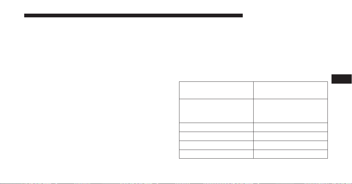
HDC has three states:
1. Off (feature is not enabled and will not activate).
2. Enabled (feature is enabled and ready but activation
conditions are not met, or driver is actively overriding
with brake or throttle application).
3. Active (feature is enabled and actively controlling
vehicle speed).
Enabling HDC
HDC is enabled by pressing the HDC switch, but the
following conditions must also be met to enable HDC:
• Driveline is in 4WD Low Range.
• Vehicle speed is below 5 mph (8 Km/h).
• Parking brake is released.
• Driver door is closed.
Activating HDC
Once HDC is enabled it will activate automatically if
driven down a grade of sufficient magnitude (greater
than approximately 8%). The set speed for HDC is
selectable by the driver, and can be adjusted by using the
Electronic range switches located on steering column
shifter. The following summarizes the HDC set speed:
Gear Approximate HDC Set
Speed
P No set speed. HDC may
be enabled but will not
activate
R 0.6 mph (1 km/h)
N 1.2 mph (2 km/h)
1st 0.6 mph (1 km/h)
2nd 1.2 mph (2 km/h)
5
STARTING AND OPERATING 605
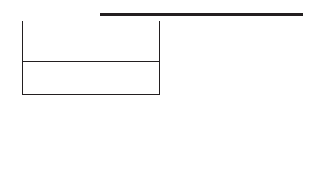
Gear Approximate HDC Set
Speed
3rd 1.8 mph (3 km/h)
4th 2.5 mph (4 km/h)
5th 3.1 mph (5 km/h)
6th 3.7 mph (6 km/h)
7th 4.3 mph (7 km/h)
8th 5.0 mph (8 km/h)
9th 5.6 mph (9 km/h)
NOTE: During HDC the ERS +/- shifter input is used for
HDC target speed selection but will not affect the gear
chosen by the transmission. During HDC the transmis-
sion will shift appropriately for the driver-selected set
speed and corresponding driving conditions.
Driver Override:
The driver may override HDC activation with throttle or
brake application at anytime.
Deactivating HDC
HDC will be deactivated but remain available if any of
the following conditions occur:
• Driver overrides HDC set speed with throttle or brake
application.
• Vehicle speed exceeds 20 mph (32 km/h) but remains
below 40 mph (64 km/h).
• Vehicle is on a downhill grade of insufficient magni-
tude (less than approximately 8%), is on level ground,
or is on an uphill grade.
• Vehicle is shifted to park.
606 STARTING AND OPERATING

Disabling HDC
HDC will deactivate and be disabled if any of the
following conditions occur:
• The driver presses the HDC switch.
• The driveline is shifted out of 4WD Low Range.
• The parking brake is applied.
• Driver door opens.
• The vehicle is driven greater than 20 mph
(32 km/h)for greater than 70 seconds.
• The vehicle is drive greater than 40 mph (64 km/h)
(HDC exits immediately).
Feedback to the driver:
The instrument cluster has a HDC icon and a HDC
switch which has an LED which offers feedback to the
driver about the state HDC is in.
• While HDC is Enabled or Active the gear position
typically associated with ERS manual mode will indi-
cate target set speed not the top gear limit which is
typical of ERS manual mode.
• The cluster icon and switch lamp will illuminate and
remain on solid when HDC is enabled or activated.
This is the normal operating condition for HDC.
• The cluster icon and switch lamp will flash for several
seconds then extinguish when the driver presses the
HDC switch but enable conditions are not met.
5
STARTING AND OPERATING 607
• The cluster icon and switch lamp will flash for several
seconds then extinguish when HDC deactivates due to
excess speed.
• The cluster icon and switch lamp will flash when HDC
deactivates due to overheated brakes. The flashing will
stop and HDC will activate again once the brakes have
cooled sufficiently.
WARNING!
HDC is only intended to assist the driver in control-
ling vehicle speed when descending hills. The driver
must remain attentive to the driving conditions and
is responsible for maintaining a safe vehicle speed.
TIRE SAFETY INFORMATION
Tire Markings
1 — U.S. DOT Safety Standards
Code (TIN)
4 — Maximum Load
2 — Size Designation 5 — Maximum Pressure
3 — Service Description 6 — Treadwear, Traction and
Temperature Grades
608 STARTING AND OPERATING

NOTE:
• P (Passenger) — Metric tire sizing is based on U.S.
design standards. P-Metric tires have the letter “P”
molded into the sidewall preceding the size designa-
tion. Example: P215/65R15 95H.
• European — Metric tire sizing is based on European
design standards. Tires designed to this standard have
the tire size molded into the sidewall beginning with
the section width. The letter ⬙P⬙ is absent from this tire
size designation. Example: 215/65R15 96H.
• LT (Light Truck) — Metric tire sizing is based on U.S.
design standards. The size designation for LT-Metric
tires is the same as for P-Metric tires except for the
letters “LT” that are molded into the sidewall preced-
ing the size designation. Example: LT235/85R16.
• Temporary spare tires are designed for temporary
emergency use only. Temporary high pressure com-
pact spare tires have the letter “T” or “S” molded into
the sidewall preceding the size designation. Example:
T145/80D18 103M.
• High flotation tire sizing is based on U.S. design
standards and it begins with the tire diameter molded
into the sidewall. Example: 31x10.5 R15 LT.
5
STARTING AND OPERATING 609

Tire Sizing Chart
EXAMPLE:
Example Size Designation: P215/65R15XL 95H, 215/65R15 96H, LT235/85R16C, T145/80D18 103M, 31x10.5 R15 LT
P = Passenger car tire size based on U.S. design standards, or
ⴖ....blank....ⴖ = Passenger car tire based on European design standards, or
LT = Light truck tire based on U.S. design standards, or
TorS= Temporary spare tire or
31 = Overall diameter in inches (in)
215, 235, 145 = Section width in millimeters (mm)
65, 85, 80 = Aspect ratio in percent (%)
– Ratio of section height to section width of tire, or
10.5 = Section width in inches (in)
610 STARTING AND OPERATING

EXAMPLE:
R = Construction code
– ⬙R⬙ means radial construction, or
– ⬙D⬙ means diagonal or bias construction
15, 16, 18 = Rim diameter in inches (in)
Service Description:
95 = Load Index
– A numerical code associated with the maximum load a tire can carry
H = Speed Symbol
– A symbol indicating the range of speeds at which a tire can carry a load corresponding to
its load index under certain operating conditions
– The maximum speed corresponding to the speed symbol should only be achieved under
specified operating conditions (i.e., tire pressure, vehicle loading, road conditions, and
posted speed limits)
5
STARTING AND OPERATING 611

EXAMPLE:
Load Identification:
Absence of the following load identification symbols on the sidewall of the tire indicates a Standard Load (SL)
tire:
•
XL = Extra load (or reinforced) tire, or
•
LL = Light load tire or
•
C, D, E, F, G = Load range associated with the maximum load a tire can carry at a specified pressure
Maximum Load – Maximum load indicates the maximum load this tire is designed to carry
Maximum Pressure – Maximum pressure indicates the maximum permissible cold tire inflation pressure for this
tire
Tire Identification Number (TIN)
The TIN may be found on one or both sides of the tire,
however, the date code may only be on one side. Tires
with white sidewalls will have the full TIN, including the
date code, located on the white sidewall side of the tire.
Look for the TIN on the outboard side of black sidewall
tires as mounted on the vehicle. If the TIN is not found on
the outboard side, then you will find it on the inboard
side of the tire.
612 STARTING AND OPERATING
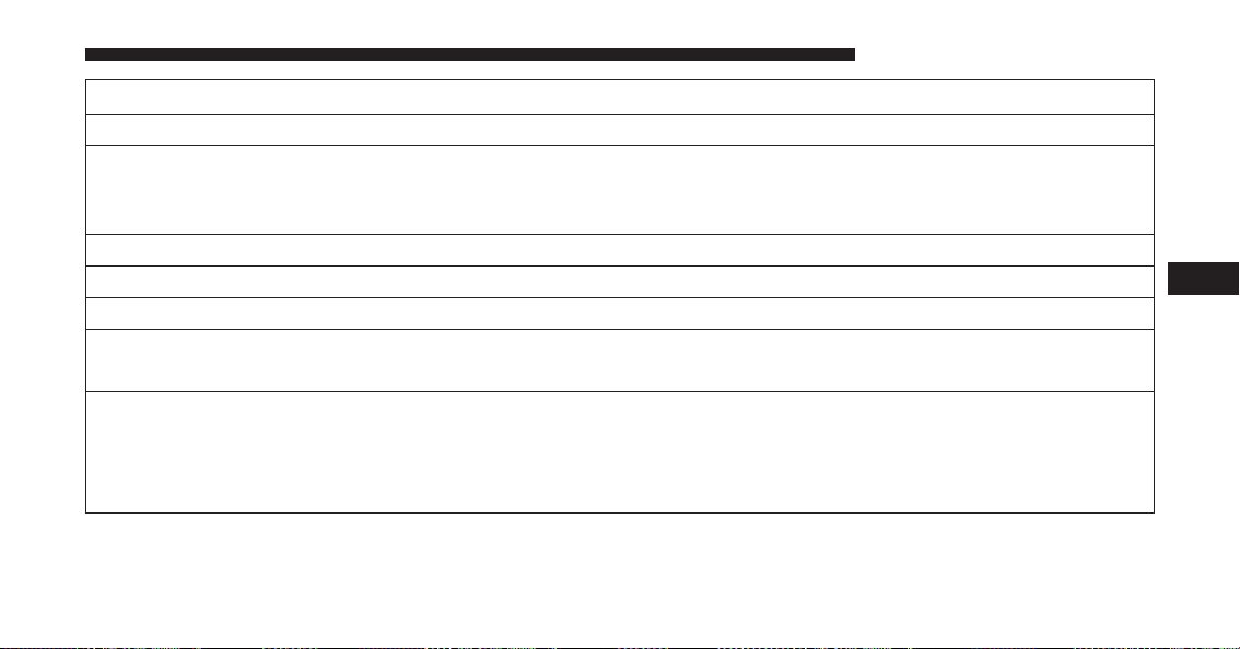
EXAMPLE:
DOT MA L9 ABCD 0301
DOT = Department of Transportation
– This symbol certifies that the tire is in compliance with the U.S. Department of Transportation tire
safety standards and is approved for highway use
MA = Code representing the tire manufacturing location (two digits)
L9 = Code representing the tire size (two digits)
ABCD = Code used by the tire manufacturer (one to four digits)
03 = Number representing the week in which the tire was manufactured (two digits)
– 03 means the 3rd week
01 = Number representing the year in which the tire was manufactured (two digits)
– 01 means the year 2001
– Prior to July 2000, tire manufacturers were only required to have one number to represent the year
in which the tire was manufactured. Example: 031 could represent the 3rd week of 1981 or 1991
5
STARTING AND OPERATING 613

Tire Terminology And Definitions
Term Definition
B-Pillar The vehicle B-Pillar is the structural member of the body located
behind the front door.
Cold Tire Inflation Pressure Cold tire inflation pressure is defined as the tire pressure after
the vehicle has not been driven for at least three hours, or driven
less than 1 mile (1.6 km) after sitting for a minimum of three
hours. Inflation pressure is measured in units of PSI (pounds per
square inch) or kPa (kilopascals).
Maximum Inflation Pressure The maximum inflation pressure is the maximum permissible
cold tire inflation pressure for this tire. The maximum inflation
pressure is molded into the sidewall.
Recommended Cold Tire Inflation
Pressure
Vehicle manufacturer’s recommended cold tire inflation pressure
as shown on the tire placard.
Tire Placard A label permanently attached to the vehicle describing the vehi-
cle’s loading capacity, the original equipment tire sizes and the
recommended cold tire inflation pressures.
614 STARTING AND OPERATING

Tire Loading And Tire Pressure
Tire And Loading Information Placard Location
NOTE: The proper cold tire inflation pressure is listed on
the driver’s side B-Pillar or the rear edge of the driver’s
side door.
Example Tire Placard Location (Door)
Example Tire Placard Location (B-Pillar)
5
STARTING AND OPERATING 615

Tire And Loading Information Placard
This placard tells you important information about the:
1. Number of people that can be carried in the vehicle.
2. Total weight your vehicle can carry.
3. Tire size designed for your vehicle.
4. Cold tire inflation pressures for the front, rear, and
spare tires.
Loading
The vehicle maximum load on the tire must not exceed
the load carrying capacity of the tire on your vehicle. You
will not exceed the tire’s load carrying capacity if you
adhere to the loading conditions, tire size, and cold tire
inflation pressures specified on the Tire and Loading
Information placard and in the “Vehicle Loading” section
of this manual.
Tire And Loading Information Placard
616 STARTING AND OPERATING

NOTE: Under a maximum loaded vehicle condition,
gross axle weight ratings (GAWRs) for the front and rear
axles must not be exceeded. For further information on
GAWRs, vehicle loading, and trailer towing, refer to
“Vehicle Loading” in this manual.
To determine the maximum loading conditions of your
vehicle, locate the statement “The combined weight of
occupants and cargo should never exceed XXX lbs or
XXX kg” on the Tire and Loading Information placard.
The combined weight of occupants, cargo/luggage and
trailer tongue weight (if applicable) should never exceed
the weight referenced here.
Steps For Determining Correct Load Limit
1. Locate the statement “The combined weight of occu-
pants and cargo should never exceed XXX lbs or
XXX kg” on your vehicle’s placard.
2. Determine the combined weight of the driver and
passengers that will be riding in your vehicle.
3. Subtract the combined weight of the driver and pas-
sengers from XXX lbs or XXX kg.
5
STARTING AND OPERATING 617

4. The resulting figure equals the available amount of
cargo and luggage load capacity. For example, if
“XXX” amount equals 1,400 lbs (635 kg) and there will
be five 150 lb (68 kg) passengers in your vehicle, the
amount of available cargo and luggage load capacity
is 650 lbs (295 kg) (since 5 x 150 lbs (68 kg) = 750 lbs
(340 kg), and 1400 lbs (635 kg) – 750 lbs (340 kg) =
650 lbs [295 kg]).
5. Determine the combined weight of luggage and cargo
being loaded on the vehicle. That weight may not
safely exceed the available cargo and luggage load
capacity calculated in step 4.
NOTE:
• If your vehicle will be towing a trailer, load from your
trailer will be transferred to your vehicle. The follow-
ing table shows examples on how to calculate total
load, cargo/luggage, and towing capacities of your
vehicle with varying seating configurations and num-
ber and size of occupants. This table is for illustration
purposes only and may not be accurate for the seating
and load carry capacity of your vehicle.
• For the following example, the combined weight of
occupants and cargo should never exceed 865 lbs
(392 kg).
618 STARTING AND OPERATING
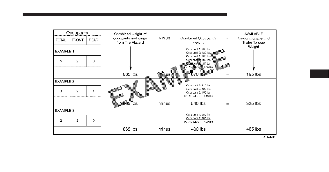
5
STARTING AND OPERATING 619
WARNING!
Overloading of your tires is dangerous. Overloading
can cause tire failure, affect vehicle handling, and
increase your stopping distance. Use tires of the
recommended load capacity for your vehicle. Never
overload them.
TIRES — GENERAL INFORMATION
Tire Pressure
Proper tire inflation pressure is essential to the safe and
satisfactory operation of your vehicle. Four primary areas
are affected by improper tire pressure:
• Safety and Vehicle Stability
• Economy
• Tread Wear
• Ride Comfort
Safety
WARNING!
• Improperly inflated tires are dangerous and can
cause collisions.
• Under-inflation increases tire flexing and can re-
sult in overheating and tire failure.
• Over-inflation reduces a tire’s ability to cushion
shock. Objects on the road and chuckholes can
cause damage that result in tire failure.
• Overinflated or under-inflated tires can affect ve-
hicle handling and can fail suddenly, resulting in
loss of vehicle control.
• Unequal tire pressures can cause steering prob-
lems. You could lose control of your vehicle.
(Continued)
620 STARTING AND OPERATING
WARNING! (Continued)
• Unequal tire pressures from one side of the vehicle
to the other can cause the vehicle to drift to the
right or left.
• Always drive with each tire inflated to the recom-
mended cold tire inflation pressure.
Both under-inflation and over-inflation affect the stability
of the vehicle and can produce a feeling of sluggish
response or over responsiveness in the steering.
NOTE:
• Unequal tire pressures from side to side may cause
erratic and unpredictable steering response.
• Unequal tire pressure from side to side may cause the
vehicle to drift left or right.
Fuel Economy
Underinflated tires will increase tire rolling resistance
resulting in higher fuel consumption.
Tread Wear
Improper cold tire inflation pressures can cause abnor-
mal wear patterns and reduced tread life, resulting in the
need for earlier tire replacement.
Ride Comfort And Vehicle Stability
Proper tire inflation contributes to a comfortable ride.
Over-inflation produces a jarring and uncomfortable
ride.
Tire Inflation Pressures
The proper cold tire inflation pressure is listed on the
driver’s side B-Pillar or rear edge of the driver’s side
door.
5
STARTING AND OPERATING 621
At least once a month:
• Check and adjust tire pressure with a good quality
pocket-type pressure gauge. Do not make a visual
judgement when determining proper inflation. Tires
may look properly inflated even when they are under-
inflated.
• Inspect tires for signs of tire wear or visible damage.
CAUTION!
After inspecting or adjusting the tire pressure, al-
ways reinstall the valve stem cap. This will prevent
moisture and dirt from entering the valve stem,
which could damage the valve stem.
Inflation pressures specified on the placard are always
“cold tire inflation pressure”. Cold tire inflation pressure
is defined as the tire pressure after the vehicle has not
been driven for at least three hours, or driven less than 1
mile (1.6 km) after sitting for a minimum of three hours.
The cold tire inflation pressure must not exceed the
maximum inflation pressure molded into the tire side-
wall.
Check tire pressures more often if subject to a wide range
of outdoor temperatures, as tire pressures vary with
temperature changes.
Tire pressures change by approximately 1 psi (7 kPa) per
12°F (7°C) of air temperature change. Keep this in mind
when checking tire pressure inside a garage, especially in
the Winter.
Example: If garage temperature = 68°F (20°C) and the
outside temperature = 32°F (0°C) then the cold tire
inflation pressure should be increased by 3 psi (21 kPa),
which equals 1 psi (7 kPa) for every 12°F (7°C) for this
outside temperature condition.
622 STARTING AND OPERATING
Tire pressure may increase from 2 to 6 psi (13 to 40 kPa)
during operation. DO NOT reduce this normal pressure
build up or your tire pressure will be too low.
Tire Pressures For High Speed Operation
The manufacturer advocates driving at safe speeds and
within posted speed limits. Where speed limits or condi-
tions are such that the vehicle can be driven at high
speeds, maintaining correct tire inflation pressure is very
important. Increased tire pressure and reduced vehicle
loading may be required for high-speed vehicle opera-
tion. Refer to your authorized tire dealer or original
equipment vehicle dealer for recommended safe operat-
ing speeds, loading and cold tire inflation pressures.
WARNING!
High speed driving with your vehicle under maxi-
mum load is dangerous. The added strain on your
tires could cause them to fail. You could have a
serious collision. Do not drive a vehicle loaded to the
maximum capacity at continuous speeds above
75 mph (120 km/h).
Radial Ply Tires
WARNING!
Combining radial ply tires with other types of tires
on your vehicle will cause your vehicle to handle
poorly. The instability could cause a collision. Al-
ways use radial ply tires in sets of four. Never
combine them with other types of tires.
5
STARTING AND OPERATING 623

Tire Repair
If your tire becomes damaged, it may be repaired if it
meets the following criteria:
• The tire has not been driven on when flat.
• The damage is only on the tread section of your tire
(sidewall damage is not repairable).
• The puncture is no greater thana¼ofaninch (6 mm).
Consult an authorized tire dealer for tire repairs and
additional information.
Damaged Run Flat tires, or Run Flat tires that have
experienced a loss of pressure should be replaced imme-
diately with another Run Flat tire of identical size and
service description (Load Index and Speed Symbol).
Tire Types
All Season Tires — If Equipped
All Season tires provide traction for all seasons (Spring,
Summer, Fall and Winter). Traction levels may vary
between different all season tires. All season tires can be
identified by the M+S, M&S, M/S or MS designation on
the tire sidewall. Use all season tires only in sets of four;
failure to do so may adversely affect the safety and
handling of your vehicle.
Summer Or Three Season Tires — If Equipped
Summer tires provide traction in both wet and dry
conditions, and are not intended to be driven in snow or
on ice. If your vehicle is equipped with Summer tires, be
aware these tires are not designed for Winter or cold
driving conditions. Install Winter tires on your vehicle
when ambient temperatures are less than 40°F (5°C) or if
roads are covered with ice or snow. For more informa-
tion, contact an authorized dealer.
624 STARTING AND OPERATING
Summer tires do not contain the all season designation or
mountain/snowflake symbol on the tire sidewall. Use
Summer tires only in sets of four; failure to do so may
adversely affect the safety and handling of your vehicle.
WARNING!
Do not use Summer tires in snow/ice conditions. You
could lose vehicle control, resulting in severe injury
or death. Driving too fast for conditions also creates
the possibility of loss of vehicle control.
Snow Tires
Some areas of the country require the use of snow tires
during the Winter. Snow tires can be identified by a
“mountain/snowflake” symbol on the tire sidewall.
If you need snow tires, select tires
equivalent in size and type to the origi-
nal equipment tires. Use snow tires
only in sets of four; failure to do so
may adversely affect the safety and
handling of your vehicle.
Snow tires generally have lower speed ratings than what
was originally equipped with your vehicle and should
not be operated at sustained speeds over 75 mph
(120 km/h). For speeds above 75 mph (120 km/h) refer to
original equipment or an authorized tire dealer for
recommended safe operating speeds, loading and cold
tire inflation pressures.
5
STARTING AND OPERATING 625
While studded tires improve performance on ice, skid
and traction capability on wet or dry surfaces may be
poorer than that of non-studded tires. Some states pro-
hibit studded tires; therefore, local laws should be
checked before using these tire types.
Run Flat Tires — If Equipped
Run Flat tires allow you the capability to drive 50 miles
(80 km) at 50 mph (80 km/h) after a rapid loss of inflation
pressure. This rapid loss of inflation is referred to as the
Run Flat mode. A Run Flat mode occurs when the tire
inflation pressure is of/or below 14 psi (96 kPa). Once a
Run Flat tire reaches the run flat mode it has limited
driving capabilities and needs to be replaced immedi-
ately. A Run Flat tire is not repairable.
It is not recommended driving a vehicle loaded at full
capacity or to tow a trailer while a tire is in the run flat
mode.
See the tire pressure monitoring section for more infor-
mation.
Spare Tires — If Equipped
NOTE: For vehicles equipped with Tire Service Kit
instead of a spare tire, please refer to “Tire Service Kit” in
“What To Do In Emergencies” for further information.
CAUTION!
Because of the reduced ground clearance, do not take
your vehicle through an automatic car wash with a
compact or limited-use temporary spare installed.
Damage to the vehicle may result.
Spare Tire Matching Original Equipped Tire And
Wheel — If Equipped
Your vehicle may be equipped with a spare tire and
wheel equivalent in look and function to the original
626 STARTING AND OPERATING
equipment tire and wheel found on the front or rear axle
of your vehicle. This spare tire may be used in the tire
rotation for your vehicle. If your vehicle has this option,
refer to an authorized tire dealer for the recommended
tire rotation pattern.
Compact Spare Tire — If Equipped
The compact spare is for temporary emergency use only.
You can identify if your vehicle is equipped with a
compact spare by looking at the spare tire description on
the Tire and Loading Information Placard located on the
driver’s side door opening or on the sidewall of the tire.
Compact spare tire descriptions begin with the letter “T”
or “S” preceding the size designation. Example: T145/
80D18 103M.
T, S = Temporary Spare Tire
Since this tire has limited tread life, the original equip-
ment tire should be repaired (or replaced) and reinstalled
on your vehicle at the first opportunity.
Do not install a wheel cover or attempt to mount a
conventional tire on the compact spare wheel, since the
wheel is designed specifically for the compact spare tire.
Do not install more than one compact spare tire and
wheel on the vehicle at any given time.
WARNING!
Compact spares are for temporary emergency use
only. With these spares, do not drive more than
50 mph (80 km/h). Temporary use spares have limited
tread life. When the tread is worn to the tread wear
indicators, the temporary use spare tire needs to be
replaced. Be sure to follow the warnings, which
apply to your spare. Failure to do so could result in
spare tire failure and loss of vehicle control.
5
STARTING AND OPERATING 627
Full Size Spare — If Equipped
The full size spare is for temporary emergency use only.
This tire may look like the originally equipped tire on the
front or rear axle of your vehicle, but it is not. This spare
tire may have limited tread life. When the tread is worn
to the tread wear indicators, the temporary use full size
spare tire needs to be replaced. Since it is not the same as
your original equipment tire, replace (or repair) the
original equipment tire and reinstall on the vehicle at the
first opportunity.
Limited-Use Spare — If Equipped
The limited-use spare tire is for temporary emergency
use only. This tire is identified by a label located on the
limited-use spare wheel. This label contains the driving
limitations for this spare. This tire may look like the
original equipped tire on the front or rear axle of your
vehicle, but it is not. Installation of this limited-use spare
tire affects vehicle handling. Since it is not the same as
your original equipment tire, replace (or repair) the
original equipment tire and reinstall on the vehicle at the
first opportunity.
WARNING!
Limited-use spares are for emergency use only. In-
stallation of this limited-use spare tire affects vehicle
handling. With this tire, do not drive more than the
speed listed on the limit-use spare wheel. Keep
inflated to the cold tire inflation pressures listed on
your Tire and Loading Information Placard located
on the driver’s side B-Pillar or the rear edge of the
driver’s side door. Replace (or repair) the original
equipment tire at the first opportunity and reinstall it
on your vehicle. Failure to do so could result in loss
of vehicle control.
628 STARTING AND OPERATING
Tire Spinning
When stuck in mud, sand, snow, or ice conditions, do not
spin your vehicle’s wheels above 30 mph (48 km/h) or
for longer than 30 seconds continuously without stop-
ping.
Refer to “Freeing A Stuck Vehicle” in “What To Do In
Emergencies” for further information.
WARNING!
Fast spinning tires can be dangerous. Forces gener-
ated by excessive wheel speeds may cause tire dam-
age or failure. A tire could explode and injure some-
one. Do not spin your vehicle’s wheels faster than
30 mph (48 km/h) for more than 30 seconds continu-
ously when you are stuck, and do not let anyone near
a spinning wheel, no matter what the speed.
Tread Wear Indicators
Tread wear indicators are in the original equipment tires
to help you in determining when your tires should be
replaced.
1—WornTire
2—NewTire
5
STARTING AND OPERATING 629
These indicators are molded into the bottom of the tread
grooves. They will appear as bands when the tread depth
becomes a 1/16 of an inch (2 mm). When the tread is
worn to the tread wear indicators, the tire should be
replaced. Refer to “Replacement Tires” in this section for
further information.
Life Of Tire
The service life of a tire is dependent upon varying
factors including, but not limited to:
• Driving style.
• Tire pressure - Improper cold tire inflation pressures
can cause uneven wear patterns to develop across the
tire tread. These abnormal wear patterns will reduce
tread life, resulting in the need for earlier tire replace-
ment.
• Distance driven.
• Performance tires, tires with a speed rating of V or
higher, and Summer tires typically have a reduced
tread life. Rotation of these tires per the vehicle main-
tenance schedule is highly recommended.
WARNING!
Tires and the spare tire should be replaced after six
years, regardless of the remaining tread. Failure to
follow this warning can result in sudden tire failure.
You could lose control and have a collision resulting
in serious injury or death.
Keep dismounted tires in a cool, dry place with as little
exposure to light as possible. Protect tires from contact
with oil, grease, and gasoline.
630 STARTING AND OPERATING
Replacement Tires
The tires on your new vehicle provide a balance of many
characteristics. They should be inspected regularly for
wear and correct cold tire inflation pressures. The manu-
facturer strongly recommends that you use tires equiva-
lent to the originals in size, quality and performance
when replacement is needed. Refer to the paragraph on
“Tread Wear Indicator”. Refer to the Tire and Loading
Information placard or the Vehicle Certification Label for
the size designation of your tire. The Load Index and
Speed Symbol for your tire will be found on the original
equipment tire sidewall. See the Tire Sizing Chart ex-
ample found in the “Tire Safety Information” section of
this manual for more information relating to the Load
Index and Speed Symbol of a tire.
It is recommended to replace the two front tires or two
rear tires as a pair. Replacing just one tire can seriously
affect your vehicle’s handling. If you ever replace a
wheel, make sure that the wheel’s specifications match
those of the original wheels.
It is recommended you contact your authorized tire
dealer or original equipment dealer with any questions
you may have on tire specifications or capability. Failure
to use equivalent replacement tires may adversely affect
the safety, handling, and ride of your vehicle.
WARNING!
• Do not use a tire, wheel size or rating other than
that specified for your vehicle. Some combinations
of unapproved tires and wheels may change sus-
pension dimensions and performance characteris-
tics, resulting in changes to steering, handling, and
(Continued)
5
STARTING AND OPERATING 631
WARNING! (Continued)
braking of your vehicle. This can cause unpredict-
able handling and stress to steering and suspen-
sion components. You could lose control and have
a collision resulting in serious injury or death. Use
only the tire and wheel sizes with load ratings
approved for your vehicle.
• Never use a tire with a smaller load index or
capacity, other than what was originally equipped
on your vehicle. Using a tire with a smaller load
index could result in tire overloading and failure.
You could lose control and have a collision.
• Failure to equip your vehicle with tires having
adequate speed capability can result in sudden tire
failure and loss of vehicle control.
CAUTION!
Replacing original tires with tires of a different size may
result in false speedometer and odometer readings.
SUPPLEMENTAL TIRE PRESSURE INFORMATION
— IF EQUIPPED
A light load vehicle condition is defined as two passen-
gers [150 lbs (68 kg) each] plus 200 lbs (91 kg) of cargo.
Cold tire inflation pressures for a lightly loaded vehicle
will be found on the face of the driver’s door.
TIRE CHAINS (TRACTION DEVICES)
Use of traction devices require sufficient tire-to-body
clearance. Follow these recommendations to guard
against damage.
• Traction device must be of proper size for the tire, as
recommended by the traction device manufacturer.
632 STARTING AND OPERATING
Please follow the table below for proper tire size, chain
type, and axle recommendations:
Vehicle Axle Recommendations Tire Sizes Chain Class
1500 Models Rear Only P265/70R17 S Class
2500 Models Rear Only LT245/70R17E
LT265/70R18E
LT275/70R18E
U Class
2500 Power Wagon
Models
Rear Only LT285/70R17D U Class
3500 (Single Rear Wheel)
Models
Rear Only LT265/70R18E
LT275/70R18E
U Class
3500 (Dual Rear Wheel)
Models
Front/Rear LT235/80R17E U Class
5
STARTING AND OPERATING 633
WARNING!
Using tires of different size and type (M+S, Snow)
between front and rear axles can cause unpredictable
handling. You could lose control and have a collision.
CAUTION!
To avoid damage to your vehicle or tires, observe the
following precautions:
• Because of restricted traction device clearance be-
tween tires and other suspension components, it is
important that only traction devices in good condi-
tion are used. Broken devices can cause serious
damage. Stop the vehicle immediately if noise
occurs that could indicate device breakage. Remove
the damaged parts of the device before further use.
(Continued)
CAUTION! (Continued)
• Install device as tightly as possible and then re-
tighten after driving about ½ mile (0.8 km).
• Do not exceed 30 mph (48 km/h).
• Drive cautiously and avoid severe turns and large
bumps, especially with a loaded vehicle.
• Do not drive for a prolonged period on dry pave-
ment.
• Observe the traction device manufacturer’s instruc-
tions on the method of installation, operating
speed, and conditions for use. Always use the
suggested operating speed of the device manufac-
turer’s if it is less than 30 mph (48 km/h).
• Do not use traction devices on a compact spare tire.
634 STARTING AND OPERATING

TIRE ROTATION RECOMMENDATIONS
Tires on the front and rear axles of vehicles operate at
different loads and perform different steering, driving,
and braking functions. For these reasons, they wear at
unequal rates.
These effects can be reduced by timely rotation of tires.
The benefits of rotation are especially worthwhile with
aggressive tread designs such as those on all season type
tires. Rotation will increase tread life, help to maintain
mud, snow and wet traction levels and contribute to a
smooth, quiet ride.
Refer to the “Maintenance Schedule” for the proper
maintenance intervals. More frequent rotation is permis-
sible if desired. The reasons for any rapid or unusual
wear should be corrected prior to rotation being per-
formed.
The suggested rotation method is the “forward cross”
shown in the following diagram. This rotation pattern
does not apply to some directional tires that must not be
reversed.
Tire Rotation
5
STARTING AND OPERATING 635

Directional Tires — If Equipped
For the R/T package with 22” tires and wheels, the
rotational direction of the tire must be taken into consid-
eration when rotating the tires. The recommended rota-
tion pattern for directional tires is shown below.
Dual Rear Wheels — If Equipped
The tires used on dual wheel assemblies should be
matched for wear to prevent overloading one tire in a set.
To check if tires are even, lay a straight edge across all
four tires. The straight edge should touch all the tires.
Tire Rotation Tire Rotation
636 STARTING AND OPERATING
NOTE: If your vehicle is equipped with a Tire Pressure
Information System (TPIS):
• The Tire Pressure Information System (TPIS) uses
unique sensors in the inner rear wheels to help identify
them from the outer rear wheels, because of this, the
inner and outer wheel locations can’t be switched.
• After a tire rotation is completed, as shown below, the
system can auto learn the locations of each sensor ID.
Auto learning/localization occurs when the vehicle
ignition status is changed from Off to On and speeds of
greater than 5 mph (8km/h) are obtained and remain
over 5 mph (8km/h) for at about a 15 minute period.
You may need to drive for 20 minutes to account
slower speeds and stops.
• If the tires are rotated incorrectly, The Auto localization
of the TPIS sensors will fail to locate correctly resulting
in incorrect locations for the pressure values displayed
in the Instrument Cluster.
CAUTION!
3500 Dual Rear Tires may only have one approved
direction of rotation. This is to accommodate the asym-
metrical design (tread pattern) of the On/Off-Road tire
and the use of Outline White Letter (OWL) tires.
• When replacing a flat, the spare tire may have to be
remounted on the rim, or installed at a different
location, to maintain the correct placement of the
tire on the wheel relative to the tire/wheel position
on the truck. For example, if the spare is used to
replace an outer rear tire it will have to be re-
mounted on the rim so that the wheel is dished
inward. That way the tread design of asymmetrical
tires and the white writing of the OWL tires will
maintain proper position.
5
STARTING AND OPERATING 637

TIRE PRESSURE MONITOR SYSTEM (TPMS)
The Tire Pressure Monitor System (TPMS) will warn the
driver of a low tire pressure based on the vehicle recom-
mended cold placard pressure.
The tire pressure will vary with temperature by about 1
psi (7 kPa) for every 12°F (6.5°C). This means that when
the outside temperature decreases, the tire pressure will
decrease. Tire pressure should always be set based on
cold inflation tire pressure. This is defined as the tire
pressure after the vehicle has not been driven for at least
three hours, or driven less than 1 mile (1.6 km) after a
three hour period. The cold tire inflation pressure must
not exceed the maximum inflation pressure molded into
the tire sidewall. Refer to “Tires – General Information”
in “Starting And Operating” for information on how to
properly inflate the vehicle’s tires. The tire pressure will
also increase as the vehicle is driven - this is normal and
there should be no adjustment for this increased pres-
sure.
The TPMS will warn the driver of a low tire pressure if
the tire pressure falls below the low-pressure warning
limit for any reason, including low temperature effects
and natural pressure loss through the tire.
The TPMS will continue to warn the driver of low tire
pressure as long as the condition exists, and will not turn
off until the tire pressure is at or above the recommended
cold placard pressure. Once the low tire pressure warn-
ing (Tire Pressure Monitoring [TPM] Telltale Light) illu-
minates, you must increase the tire pressure to the
recommended cold placard pressure in order for the “Tire
Pressure Monitoring Telltale Light” to turn off. The
system will automatically update and the “Tire Pressure
Monitoring Telltale Light” will turn off once the system
receives the updated tire pressures. The vehicle may need
638 STARTING AND OPERATING
to be driven for up to 20 minutes above 15 mph
(25 km/h) in order for the TPMS to receive this informa-
tion.
For example, your vehicle may have a recommended
cold (parked for more than three hours) placard pressure
of 30 psi (207 kPa). If the ambient temperature is 68°F
(20°C) and the measured tire pressure is 27 psi (186 kPa),
a temperature drop to 20°F (-7°C) will decrease the tire
pressure to approximately 23 psi (158 kPa). This tire
pressure is sufficiently low enough to turn ON the “Tire
Pressure Monitoring Telltale Light.” Driving the vehicle
may cause the tire pressure to rise to approximately 27
psi (186 kPa), but the “Tire Pressure Monitoring Telltale
Light” will still be ON. In this situation, the “Tire
Pressure Monitoring Telltale Light” will turn OFF only
after the tires are inflated to the vehicle’s recommended
cold placard pressure value.
CAUTION!
• The TPMS has been optimized for the original
equipment tires and wheels. TPMS pressures have
been established for the tire size equipped on your
vehicle. Undesirable system operation or sensor
damage may result when using replacement equip-
ment that is not of the same size, type, and/or style.
Aftermarket wheels can cause sensor damage. Us-
ing aftermarket tire sealants may cause the Tire
Pressure Monitoring System (TPMS) sensor to be-
come inoperable. After using an aftermarket tire
sealant it is recommended that you take your
vehicle to an authorized dealership to have your
sensor function checked.
• After inspecting or adjusting the tire pressure al-
ways reinstall the valve stem cap. This will prevent
moisture and dirt from entering the valve stem,
which could damage the TPMS sensor.
5
STARTING AND OPERATING 639

NOTE:
• The TPMS is not intended to replace normal tire care
and maintenance or to provide warning of a tire failure
or condition.
• The TPMS should not be used as a tire pressure gauge
while adjusting your tire pressure.
• Driving on a significantly under-inflated tire causes
the tire to overheat and can lead to tire failure.
Under-inflation also reduces fuel efficiency and tire
tread life, and may affect the vehicle’s handling and
stopping ability.
• The TPMS is not a substitute for proper tire mainte-
nance, and it is the driver’s responsibility to maintain
correct tire pressure using an accurate tire pressure
gauge, even if under-inflation has not reached the level
to trigger illumination of the “Tire Pressure Monitor-
ing Telltale Light.”
• Seasonal temperature changes will affect tire pressure,
and the TPMS will monitor the actual tire pressure in
the tire.
Premium System
The Tire Pressure Monitor System (TPMS) uses wireless
technology with wheel rim mounted electronic sensors to
monitor tire pressure levels. Sensors mounted to each
wheel as part of the valve stem transmit tire pressure
readings to the receiver module.
NOTE: It is particularly important for you to check the
tire pressure in all of the tires on your vehicle monthly
and to maintain the proper pressure.
The TPMS consists of the following components:
• Receiver module
• Four TPM sensors
640 STARTING AND OPERATING

• Various TPMS messages, which display in the Elec-
tronic Vehicle Information Center (EVIC)/Driver In-
formation Display (DID)
• TPM Telltale Light
The matching full size spare wheel and tire assembly (if
equipped) has a TPM sensor. The full size spare can be
used in place of any of the four road tires. A spare with a
pressure below the low-pressure limit will not cause the
“Tire Pressure Monitoring Telltale Light” to illuminate or
the chime to sound while it is stored in the spare tire
location.
Tire Pressure Monitoring Low Pressure Warnings
The “Tire Pressure Monitoring Telltale Light” will
illuminate in the instrument cluster and a chime
will sound when tire pressure is low in one or more of the
four active road tires. In addition, the EVIC/DID will
display a “LOW TIRE” message and a graphic showing
the pressure values of each tire with the low tire pressure
values in a different color. An ⬙Inflate to XX⬙ message will
also be displayed.
Should this occur, you should stop as soon as possible
and inflate the tires with a low pressure condition (those
in a different color in the EVIC/DID graphic) to the
“LOW TIRE PRESSURE” Message
5
STARTING AND OPERATING 641

vehicle’s recommended cold placard pressure inflation
value as shown in the ⬙Inflate to XX⬙ message. Once the
system receives the updated tire pressures, the system
will automatically update, the graphic display in the
EVIC/DID will return to it’s original color, and the “Tire
Pressure Monitoring Telltale Light” will turn off. The
vehicle may need to be driven for up to 20 minutes above
15 mph (24 km/h) in order for the TPMS to receive this
information.
Service TPMS Warning
If a system fault is detected, the “Tire Pressure Monitor-
ing Telltale Light” will flash on and off for 75 seconds and
then remain on solid. The system fault will also sound a
chime. In addition, the EVIC/DID will display a ⬙SER-
VICE TPM SYSTEM⬙ message for a minimum of five
seconds and then display dashes (- -) in place of the
pressure value to indicate which sensor is not being
received.
If the ignition switch is cycled, this sequence will repeat,
providing the system fault still exists. If the system fault
no longer exists, the “Tire Pressure Monitoring Telltale
Light” will no longer flash, and the ⬙SERVICE TPM
Tire Pressure Monitor Display
642 STARTING AND OPERATING

SYSTEM⬙ message will no longer display, and a pressure
value will display in place of the dashes. A system fault
can occur due to any of the following:
• Signal interference due to electronic devices or driving
next to facilities emitting the same radio frequencies as
the TPM sensors.
• Installing aftermarket window tinting that contains
materials that may block radio wave signals.
• Accumulation of snow or ice around the wheels or
wheel housings.
• Using tire chains on the vehicle.
• Using wheels/tires not equipped with TPM sensors.
Vehicles With Matching Full Size Spare
• The matching full size spare wheel and tire assembly
has a TPM sensor that can be monitored by the TPMS.
• If you install the full size spare in place of a road tire
that has a pressure below the low-pressure warning
limit, upon the next ignition switch cycle, a chime will
sound and the “Tire Pressure Monitoring Telltale
Light” will turn ON. In addition, the EVIC/DID will
display a “LOW TIRE” message and a graphic show-
ing the low tire pressure value in a different color. An
⬙Inflate to XX⬙ message will also be displayed.
• After driving the vehicle for up to 20 minutes above
15 mph (25 km/h) the “Tire Pressure Monitoring
Telltale Light” will turn OFF and the pressure value
will be updated and return to it’s original color, as long
as no tire pressure is below the low-pressure warning
limit in any of the four active road tires.
5
STARTING AND OPERATING 643

Vehicles With Non Matching Full Size Spare Or Com-
pact Spare
• The non matching full size spare or compact spare tire
does not have a TPM sensor. Therefore, the TPMS will
not monitor the pressure in the non matching full size
spare or compact spare tire.
• If you install the non matching full size spare or
compact spare tire in place of a road tire that has a
pressure below the low-pressure warning limit, upon
the next ignition switch cycle, the TPM Telltale Light
and a “LOW TIRE” message will remain ON and a
chime will sound. In addition, the graphic in the
EVIC/DID will still display a flashing pressure value
or a pressure value in a different color.
• After driving the vehicle for up to 20 minutes above
15 mph (24 km/h), the TPM Telltale Light will flash on
and off for 75 seconds and then remain on solid. In
addition, the EVIC/DID will display a ⬙SERVICE TPM
SYSTEM⬙ message for a minimum of five seconds and
then display dashes (- -) in place of the pressure value.
• For each subsequent ignition switch cycle, a chime will
sound, the TPM Telltale Light will flash on and off for
75 seconds and then remain on solid, and the EVIC/
DID will display a ⬙SERVICE TPM SYSTEM⬙ message
for a minimum of five seconds and then display
dashes (- -) in place of the pressure value.
• Once you repair or replace the original road tire and
reinstall it on the vehicle in place of the non matching
full size spare or compact spare, the TPMS will update
automatically. In addition, the TPM Telltale Light will
turn OFF and the graphic in the EVIC/DID will
display a new pressure value instead of dashes (- -), as
long as no tire pressure is below the low-pressure
warning limit in any of the four active road tires. The
644 STARTING AND OPERATING

vehicle may need to be driven for up to 20 minutes
above 15 mph (24 km/h) in order for the TPMS to
receive this information.
Tire Pressure Information System (TPIS) 3500
Series Trucks
Your vehicle may be equipped with a Tire Pressure
Information System (TPIS).
The Tire Pressure Information System (TPIS) uses wire-
less technology with wheel rim mounted electronic sen-
sors to transmit tire pressure levels. Sensors mounted to
each wheel as part of the valve stem transmit tire
pressure readings to the receiver module.
NOTE: It is particularly important for you to check the
tire pressure in all of the tires on your vehicle monthly
and to maintain the proper pressure.
The TPIS consists of the following components:
• Receiver module
• Four TPM sensors (Single Rear Wheel (SRW) applica-
tions)
• Six TPM sensors (Dual Rear Wheel (DRW) applica-
tions)
• Pressure display in the Electronic Vehicle Information
Center (EVIC)/Driver Information Display (DID)
The TPIS system will display all four (Single Rear Wheel
(SRW) applications) or six (Dual Rear Wheel (DRW)
applications) tire pressure values in the EVIC/DID dis-
play.
If a system fault is detected, the EVIC/DID will display a
⬙SERVICE TPM SYSTEM⬙ message for a minimum of five
seconds and then display dashes (- -) in place of the
pressure value to indicate which sensor is not being
received.
5
STARTING AND OPERATING 645

If the ignition switch is cycled, this sequence will repeat,
providing the system fault still exists. If the system fault
no longer exists, the ⬙SERVICE TPM SYSTEM⬙ message
will no longer be displayed, and a pressure value will
display in place of the dashes. A system fault can occur
due to any of the following:
• Signal interference due to electronic devices or driving
next to facilities emitting the same radio frequencies as
the TPM sensors.
• Installing aftermarket window tinting that contains
materials that may block radio wave signals.
• Accumulation of snow or ice around the wheels or
wheel housings.
• Using tire chains on the vehicle.
• Using wheels/tires not equipped with TPM sensors.
General Information
This device complies with Part 15 of the FCC rules and
RSS 210 of Industry Canada. Operation is subject to the
following conditions:
1. This device may not cause harmful interference.
2. This device must accept any interference received,
including interference that may cause undesired op-
eration.
NOTE: Changes or modifications not expressly approved
by the party responsible for compliance could void the
user’s authority to operate the equipment.
646 STARTING AND OPERATING

FUEL REQUIREMENTS
3.6L Engine
This engine is designed to meet all emis-
sions regulations and provide excellent
fuel economy and performance when us-
ing high-quality unleaded “regular” gaso-
line having an octane rating of 87. The use
of higher octane premium gasoline will not provide any
benefit over regular gasoline in these engines.
Light spark knock at low engine speeds is not harmful to
your engine. However, continued heavy spark knock at
high engine speeds can cause damage and immediate
service is required.
Poor quality gasoline can cause problems such as hard
starting, stalling, and hesitations. If you experience these
symptoms, try another brand of gasoline before consid-
ering service for the vehicle. Engine damage resulting
from operating with a heavy spark knock may void or
not be covered by the New Vehicle Limited Warranty.
5.7L/6.4L Engines
This engine is designed to meet all emis-
sions regulations and provide satisfactory
fuel economy and performance when us-
ing high quality unleaded gasoline having
an octane range of 87 to 89. The manufac-
turer recommends the use of 89 octane for optimum
performance. The use of premium gasoline (Over 89
octane) is not recommended, as it will not provide any
benefit over regular gasoline in these engines.
Light spark knock at low engine speeds is not harmful to
your engine. However, continued heavy spark knock at
high speeds can cause damage and immediate service is
required. Poor quality gasoline can cause problems such
5
STARTING AND OPERATING 647
as hard starting, stalling, and hesitations. If you experi-
ence these symptoms, try another brand of gasoline
before considering service for the vehicle.
Over 40 auto manufacturer’s world wide have issued and
endorsed consistent gasoline specifications (the World-
wide Fuel Charter, WWFC) which define fuel properties
necessary to deliver enhanced emissions, performance,
and durability for your vehicle. The manufacturer recom-
mends the use of gasolines that meet the WWFC speci-
fications, if they are available.
Reformulated Gasoline
Many areas of the country require the use of cleaner
burning gasoline referred to as “Reformulated Gasoline.”
Reformulated gasoline contain oxygenates and are spe-
cifically blended to reduce vehicle emissions and im-
prove air quality.
The use of reformulated gasoline is recommended. Prop-
erly blended reformulated gasoline will provide im-
proved performance and durability of engine and fuel
system components.
Gasoline/Oxygenate Blends
Some fuel suppliers blend unleaded gasoline with oxy-
genates such as ethanol.
CAUTION!
DO NOT use gasoline containing Methanol or gaso-
line containing more than 10% Ethanol. Use of these
blends may result in starting and drivability prob-
lems, damage critical fuel system components, cause
emissions to exceed the applicable standard, and/or
cause the “Malfunction Indicator Light” to illumi-
nate. Please observe pump labels as they should
clearly communicate if a fuel contains greater than
10% ethanol.
648 STARTING AND OPERATING

Problems that result from using gasoline containing
Methanol or gasoline containing more than 10% ethanol
are not the responsibility of the manufacturer and may
void or not be covered under New Vehicle Limited
Warranty.
E-85 Usage In Non-Flex Fuel Vehicles
Non-Flex Fuel Vehicles (FFV) are compatible with gaso-
line containing up to 10% ethanol (E10). Gasoline with
higher ethanol content may void the New Vehicle Lim-
ited Warranty.
If a Non-FFV vehicle is inadvertently fueled with E-85
fuel, the engine will have some or all of these symptoms:
• Operate in a lean mode.
• OBD II “Malfunction Indicator Light” on.
• Poor engine performance.
• Poor cold start and cold drivability.
• Increased risk for fuel system component corrosion.
MMT In Gasoline
Methylcyclopentadienyl Manganese Tricarbonyl (MMT)
is a manganese-containing metallic additive that is
blended into some gasoline to increase octane. Gasoline
blended with MMT provides no performance advantage
beyond gasoline of the same octane number without
MMT. Gasoline blended with MMT reduces spark plug
life and reduces emissions system performance in some
vehicles. The manufacturer recommends that gasoline
without MMT be used in your vehicle. The MMT content
of gasoline may not be indicated on the gasoline pump,
therefore, you should ask your gasoline retailer whether
the gasoline contains MMT. MMT is prohibited in Federal
and California reformulated gasoline.
5
STARTING AND OPERATING 649

Materials Added To Fuel
Besides using unleaded gasoline with the proper octane
rating, gasolines that contain detergents, corrosion and
stability additives are recommended. Using gasolines
that have these additives will help improve fuel
economy, reduce emissions, and maintain vehicle perfor-
mance. Designated TOP TIER Detergent Gasoline con-
tains a higher level of detergents to further aide in
minimizing engine and fuel system deposits. When avail-
able the usage of Top Tier Detergent gasoline is recom-
mended. Visit www.toptiergas.com for a list of TOP TIER
Detergent Gasoline Retailers.
Indiscriminate use of fuel system cleaning agents should
be avoided. Many of these materials intended for gum
and varnish removal may contain active solvents or
similar ingredients. These can harm fuel system gasket
and diaphragm materials.
Fuel System Cautions
CAUTION!
Follow these guidelines to maintain your vehicle’s
performance:
• The use of leaded gasoline is prohibited by Federal
law. Using leaded gasoline can impair engine per-
formance and damage the emissions control sys-
tem.
• An out-of-tune engine or certain fuel or ignition
malfunctions can cause the catalytic converter to
overheat. If you notice a pungent burning odor or
some light smoke, your engine may be out of tune
or malfunctioning and may require immediate ser-
vice. Contact your authorized dealer for service
assistance.
(Continued)
650 STARTING AND OPERATING
CAUTION! (Continued)
• The use of fuel additives, which are now being
sold as octane enhancers, is not recommended.
Most of these products contain high concentrations
of methanol. Fuel system damage or vehicle perfor-
mance problems resulting from the use of such
fuels or additives is not the responsibility of the
manufacturer and may void or not be covered
under the New Vehicle Limited Warranty.
NOTE: Intentional tampering with the emissions control
system can result in civil penalties being assessed against
you.
Carbon Monoxide Warnings
WARNING!
Carbon monoxide (CO) in exhaust gases is deadly.
Follow the precautions below to prevent carbon
monoxide poisoning:
• Do not inhale exhaust gases. They contain carbon
monoxide, a colorless and odorless gas, which can
kill. Never run the engine in a closed area, such as
a garage, and never sit in a parked vehicle with the
engine running for an extended period. If the
vehicle is stopped in an open area with the engine
running for more than a short period, adjust the
ventilation system to force fresh, outside air into
the vehicle.
• Guard against carbon monoxide with proper main-
tenance. Have the exhaust system inspected every
(Continued)
5
STARTING AND OPERATING 651
WARNING! (Continued)
time the vehicle is raised. Have any abnormal
conditions repaired promptly. Until repaired, drive
with all side windows fully open.
FLEXIBLE FUEL (3.6L ENGINE ONLY) — IF
EQUIPPED
E-85 General Information
The information in this section is unique for Flexible Fuel
vehicles only. These vehicles can be identified by a
unique fuel filler door label that states Ethanol (E-85) or
Unleaded Gasoline Only and a yellow fuel cap. Please
refer to the other sections of this manual for information
on features that are common between Flexible Fuel and
non-Flexible Fuel powered vehicles.
CAUTION!
Only vehicles with the E-85 fuel filler door label can
operate on E-85.
Ethanol Fuel (E-85)
E-85 is a mixture of approximately 85% ethanol and 15%
unleaded gasoline.
WARNING!
Ethanol vapors are extremely flammable and could
cause serious personal injury. Never have any smok-
ing materials lit or products that can cause spark in or
near the vehicle when removing the fuel filler tube
cap (gas cap) or filling the tank. Do not use E-85 as a
cleaning agent and never use it near an open flame.
652 STARTING AND OPERATING

Fuel Requirements
Your vehicle will operate on both unleaded gasoline with
any octane rating, or solely E-85 fuel, or any mixture of
these fuels. For best results, avoid refueling pattern
alternating between E-85 and unleaded gasoline.
When switching fuel types:
• Add 5 gallons (19 liters) or more when refueling.
• You operate the vehicle immediately after refueling for
a period of at least 5 minutes.
Observing these precautions will avoid possible hard
starting and/or significant deterioration in driveability
during warm up.
NOTE:
• When the ambient temperature is above 90° F (32° C),
you may experience hard starting and rough idle
following start up even if the above recommendations
are followed.
• Some additives used in regular gasoline are not fully
compatible with E-85 and may form deposits in your
engine. To eliminate driveability issues that may be
caused by these deposits, a supplemental gasoline
additive, such as MOPAR® Injector Cleanup or
Techron may be used.
Selection Of Engine Oil For Flexible Fuel Vehicles
(E-85) And Gasoline Vehicles
FFV vehicles operated on E-85 require specially formu-
lated engine oils. These special requirements are included
in MOPAR® engine oils, and in equivalent oils meeting
FCA US Material Standard MS-6395. It is recommended
5
STARTING AND OPERATING 653
that engine oils that are API Certified and meet the
requirements of Material Standard MS-6395 be used.
MS-6395 contains additional requirements, developed
during extensive fleet testing, to provide additional pro-
tection to FCA US LLC engines.
Starting
The characteristics of E-85 fuel make it unsuitable for use
when ambient temperatures fall below 0°F (-18°C). In the
range of 0°F (-18°C) to 32°F (0°C), an increase in the time
it takes for your engine to start may be experienced, and
a deterioration in driveability (sags and/or hesitations)
until the engine is fully warmed up. These issues may be
improved with the use of seasonally adjusted E-85 fuel.
NOTE: Use of the engine block heater (if equipped) may
improve engine start time when using E-85 fuel when the
ambient temperature is less than 32°F (0°C).
Cruising Range
Because E-85 fuel contains less energy per gallon/liter
than gasoline, an increase in fuel consumption will be
experienced. The miles per gallon (mpg)/kilometers per
liter and the driving range will decrease by approxi-
mately 30%, compared to gasoline operation.
Replacement Parts
All fuel and engine components in your Flexible Fuel
Vehicle (FFV) are designed to be compatible with ethanol.
Ethanol compatible service components are required.
CAUTION!
Replacing fuel system components with non-ethanol
compatible components can damage your vehicle.
654 STARTING AND OPERATING
Maintenance
CAUTION!
Do not use ethanol mixture greater than 85% in your
vehicle. It will cause difficulty in cold starting and
may affect drivability.
ADDING FUEL
The fuel filler cap (gas cap) is located behind the fuel
filler door, on the left side of the vehicle. Open the fuel
door and remove the fuel cap by turning it counter-
clockwise.
NOTE: When removing the fuel filler cap, lay the cap
tether in the hook, located on the fuel filler door.
Fuel Filler Cap
5
STARTING AND OPERATING 655
CAUTION!
• Damage to the fuel system or emissions control
system could result from using an improper fuel
tank filler tube cap.
• A poorly fitting fuel filler cap could let impurities
into the fuel system.
• A poorly fitting fuel filler cap may cause the
“Malfunction Indicator Light (MIL)” to turn on.
• To avoid fuel spillage and overfilling, do not “top
off” the fuel tank after filling. When the fuel
nozzle “clicks” or shuts off, the fuel tank is full.
WARNING!
• Never have any smoking materials lit in or near the
vehicle when the gas cap is removed or the tank is
being filled.
(Continued)
WARNING! (Continued)
• Never add fuel to the vehicle when the engine is
running.
• A fire may result if gasoline is pumped into a
portable container that is inside of a vehicle. You
could be burned. Always place gas containers on
the ground while filling.
NOTE:
• When the fuel nozzle “clicks” or shuts off, the fuel tank
is full.
• Tighten the gas cap until you hear a “clicking” sound.
This is an indication that the gas cap is tightened
properly. The MIL in the instrument cluster may turn
on if the gas cap is not secured properly. Make sure
that the gas cap is tightened each time the vehicle is
refueled.
656 STARTING AND OPERATING
WARNING!
Static electricity can cause an ignition of flammable
liquid, vapor or gas in any vehicle or trailer. To
reduce risk of serious injury or death when filling
containers:
• Always place container on the ground before fill-
ing.
• Keep the pump nozzle in contact with the container
when you are filling it.
• Use only approved containers for flammable liq-
uid.
• Do not leave container unattended while filling.
• A static electric charge could cause a spark and fire
hazard.
Loose Fuel Filler Cap Message
If the vehicle diagnostic system determines
that the fuel filler cap is loose, improperly
installed, or damaged, a loose gascap indicator
will display in the EVIC/DID telltale display
area. Refer to “Electronic Vehicle Information Center
(EVIC)/Driver Information Display (DID) in “Under-
standing Your Instrument Panel” for further information.
Tighten the fuel filler cap properly and push the RIGHT
button to turn off the message. If the problem continues,
the message will appear the next time the vehicle is
started.
5
STARTING AND OPERATING 657

VEHICLE LOADING
Certification Label
As required by National Highway Traffic Safety Admin-
istration regulations, your vehicle has a certification label
affixed to the driver’s side door or pillar.
This label contains the month and year of manufacture,
Gross Vehicle Weight Rating (GVWR), Gross Axle Weight
Rating (GAWR) front and rear, and Vehicle Identification
Number (VIN). A Month-Day-Hour (MDH) number is
included on this label and indicates the Month, Day and
Hour of manufacture. The bar code that appears on the
bottom of the label is your VIN.
Gross Vehicle Weight Rating (GVWR)
The GVWR is the total permissible weight of your vehicle
including driver, passengers, vehicle, options and cargo.
The label also specifies maximum capacities of front and
rear axle systems (GAWR). Total load must be limited so
GVWR and front and rear GAWR are not exceeded.
Payload
The payload of a vehicle is defined as the allowable load
weight a truck can carry, including the weight of the
driver, all passengers, options and cargo.
Gross Axle Weight Rating (GAWR)
The GAWR is the maximum permissible load on the front
and rear axles. The load must be distributed in the cargo
area so that the GAWR of each axle is not exceeded.
Each axle GAWR is determined by the components in the
system with the lowest load carrying capacity (axle,
springs, tires or wheels). Heavier axles or suspension
components sometimes specified by purchasers for in-
creased durability does not necessarily increase the vehi-
cle’s GVWR.
658 STARTING AND OPERATING

Tire Size
The tire size on the Vehicle Certification Label represents
the actual tire size on your vehicle. Replacement tires
must be equal to the load capacity of this tire size.
Rim Size
This is the rim size that is appropriate for the tire size
listed.
Inflation Pressure
This is the cold tire inflation pressure for your vehicle for
all loading conditions up to full GAWR.
Curb Weight
The curb weight of a vehicle is defined as the total weight
of the vehicle with all fluids, including vehicle fuel, at full
capacity conditions, and with no occupants or cargo
loaded into the vehicle. The front and rear curb weight
values are determined by weighing your vehicle on a
commercial scale before any occupants or cargo are
added.
Loading
The actual total weight and the weight of the front and
rear of your vehicle at the ground can best be determined
by weighing it when it is loaded and ready for operation.
The entire vehicle should first be weighed on a commer-
cial scale to insure that the GVWR has not been exceeded.
The weight on the front and rear of the vehicle should
then be determined separately to be sure that the load is
properly distributed over the front and rear axle. Weigh-
ing the vehicle may show that the GAWR of either the
front or rear axles has been exceeded but the total load is
within the specified GVWR. If so, weight must be shifted
from front to rear or rear to front as appropriate until the
specified weight limitations are met. Store the heavier
5
STARTING AND OPERATING 659

items down low and be sure that the weight is distributed
equally. Stow all loose items securely before driving.
Improper weight distributions can have an adverse effect
on the way your vehicle steers and handles and the way
the brakes operate.
CAUTION!
Do not load your vehicle any heavier than the GVWR
or the maximum front and rear GAWR. If you do,
parts on your vehicle can break, or it can change the
way your vehicle handles. This could cause you to
lose control. Also overloading can shorten the life of
your vehicle.
TRAILER TOWING
In this section you will find safety tips and information
on limits to the type of towing you can reasonably do
with your vehicle. Before towing a trailer, carefully
review this information to tow your load as efficiently
and safely as possible.
To maintain the New Vehicle Limited Warranty coverage,
follow the requirements and recommendations in this
manual concerning vehicles used for trailer towing.
Common Towing Definitions
The following trailer towing related definitions will assist
you in understanding the following information:
Gross Vehicle Weight Rating (GVWR)
The GVWR is the total allowable weight of your vehicle.
This includes driver, passengers, cargo and tongue
weight. The total load must be limited so that you do not
660 STARTING AND OPERATING
exceed the GVWR. Refer to “Vehicle Loading/Vehicle
Certification Label” in “Starting And Operating” for
further information.
Gross Trailer Weight (GTW)
The GTW is the weight of the trailer plus the weight of all
cargo, consumables and equipment (permanent or tem-
porary) loaded in or on the trailer in its ⬙loaded and
ready for operation⬙ condition.
The recommended way to measure GTW is to put your
fully loaded trailer on a vehicle scale. The entire weight
of the trailer must be supported by the scale.
WARNING!
If the gross trailer weight is 5,000 lbs (2 267 kg) or
more, it is mandatory to use a weight-distributing
hitch to ensure stable handling of your vehicle. If
(Continued)
WARNING! (Continued)
you use a standard weight-carrying hitch, you could
lose control of your vehicle and cause a collision.
Gross Combination Weight Rating (GCWR)
The GCWR is the total permissible weight of your vehicle
and trailer when weighed in combination.
Gross Axle Weight Rating (GAWR)
The GAWR is the maximum capacity of the front and rear
axles. Distribute the load over the front and rear axles
evenly. Make sure that you do not exceed either front or
rear GAWR. Refer to “Vehicle Loading/Vehicle Certifica-
tion Label” in “Starting And Operating” for further
information.
5
STARTING AND OPERATING 661
WARNING!
It is important that you do not exceed the maximum
front or rear GAWR. A dangerous driving condition
can result if either rating is exceeded. You could lose
control of the vehicle and have an accident.
Tongue Weight (TW)
The tongue weight is the downward force exerted on the
hitch ball by the trailer. The recommended tongue weight
is 10% to 15% of the vehicle’s GTW for a conventional
hitch. You must consider this as part of the load on your
vehicle.
Frontal Area
The frontal area is the maximum height multiplied by the
maximum width of the front of a trailer.
Trailer Sway Control
The trailer sway control can be a mechanical telescoping
link that can be installed between the hitch receiver and
the trailer tongue that typically provides adjustable fric-
tion associated with the telescoping motion to dampen
any unwanted trailer swaying motions while traveling.
If equipped, the electronic Trailer Sway Control (TSC)
recognizes a swaying trailer and automatically applies
individual wheel brakes and/or reduces engine power to
attempt to eliminate the trailer sway.
Weight-Carrying Hitch
A weight-carrying hitch supports the trailer tongue
weight, just as if it were luggage located at a hitch ball or
some other connecting point of the vehicle. These kinds
of hitches are the most popular on the market today and
they are commonly used to tow small and medium sized
trailers.
662 STARTING AND OPERATING
Weight-Distributing Hitch
A weight-distributing system works by applying lever-
age through spring (load) bars. They are typically used
for heavier loads to distribute trailer tongue weight to the
tow vehicle’s front axle and the trailer axle(s). When used
in accordance with the manufacturer’s directions, it pro-
vides for a more level ride, offering more consistent
steering and brake control, thereby enhancing towing
safety. The addition of a friction/hydraulic sway control
also dampens sway caused by traffic and crosswinds and
contributes positively to tow vehicle and trailer stability.
Trailer sway control and a weight distributing (load
equalizing) hitch are recommended for heavier Tongue
Weights (TW) and may be required depending on vehicle
and trailer configuration/loading to comply with GAWR
requirements.
WARNING!
• An improperly adjusted weight distributing hitch
system may reduce handling, stability and braking
performance and could result in a collision.
• Weight distributing systems may not be compat-
ible with surge brake couplers. Consult with your
hitch and trailer manufacturer or a reputable Rec-
reational Vehicle dealer for additional information.
5
STARTING AND OPERATING 663

Without Weight-Distributing Hitch (Incorrect) With Weight-Distributing Hitch (Correct)
664 STARTING AND OPERATING

Recommended Distribution Hitch Adjustment
Towing With 1500 Air Suspension
1. Set air suspension to normal ride height. No action is
required if already in normal ride height.
NOTE: The vehicle must remain in the engine running
position while attaching a trailer for proper leveling of
the air suspension system.
2. Position the truck to be ready to connect to the trailer
(do not connect the trailer).
3. Under radio suspension settings, turn on jack mode.
Jack mode will be canceled and procedure must be
restarted if the vehicle is driven at speeds above 5mph
(8kph).
4. Measure the height of the top of the front wheel
opening on the fender to ground, this is height H1.
Improper Adjustment Of Weight-Distributing Hitch
(Incorrect)
5
STARTING AND OPERATING 665
5. Attach the trailer to the vehicle without the weight
distribution bars connected.
6. Measure the height of the top of the front wheel
opening on the fender to ground, this is height H2.
7. Install and adjust the tension in the weight distribut-
ing bars so that the height of the front fender is
approximately (H2-H1)/3+H1 (about 1/3 the differ-
ence between H2 and H1 above normal ride height
[H1]).
8. The truck can now be driven. Jack mode will be
canceled and vehicle will return to normal ride height
when drive at speeds above 5mph (8kph).
Measurement Example
Example 1500 Height
(mm)
H1 925
H2 946
H2-H1 21
(H2-H1)/3 7
(H2-H1)/3 + H1 932
Measuring Height (H)
666 STARTING AND OPERATING
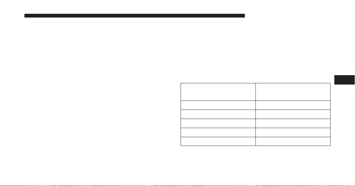
NOTE: For all towing conditions, we recommend towing
with tow haul mode engaged.
All Other 1500(Non-Air Suspension)/2500/3500 Trucks
1. Position the truck to be ready to connect to the trailer
(do not connect the trailer).
NOTE: For Ram 2500/3500 trucks equipped with rear air
suspension, normal ride height or alternate ride height
can be used. The vehicle must remain in the engine
running position while attaching a trailer for proper
leveling of the air suspension system. It may not be
possible to enter alternate ride height while lightly
loaded.
2. Measure the height of the top of the front wheel
opening on the fender to ground, this is height H1.
3. Attach the trailer to the vehicle without the weight
distribution bars connected.
4. Measure the height of the top of the front wheel
opening on the fender to ground, this is height H2.
5. Install and adjust the tension in the weight distribut-
ing bars so that the height of the front fender is
approximately (H2-H1)/2+H1 (about 1/2 the differ-
ence between H2 and H1 above normal ride height
[H1]).
Measurement Example
Example 2500/3500
Height (mm)
H1 1030
H2 1058
H2-H1 28
(H2-H1)/2 14
(H2-H1)/2 + H1 1044
NOTE: For all towing conditions, we recommend towing
with tow haul mode engaged.
5
STARTING AND OPERATING 667

Fifth-Wheel Hitch
The fifth-wheel hitch is a special high platform with a
coupling that mounts over the rear axle of the tow vehicle
in the truck bed. It connects a vehicle and fifth-wheel
trailer with a coupling king pin.
Gooseneck Hitch
The gooseneck hitch employs a pivoted coupling arm
which attaches to a ball mounted in the bed of a pickup
truck. The coupling arm connects to the hitch mounted
over the rear axle in the truck bed.
Trailer Hitch Type and Maximum Trailer Weight
The following chart provides the maximum trailer
weight a given factory equipped trailer hitch type can
tow and should be used to assist you in selecting the
correct trailer hitch for your intended towing condition.
Trailer Hitch Type and Maximum Trailer Weight
Hitch Type Max. Trailer Weight / Max.
Tongue Weight
Class III Bumper
Hitch - 1500 Model
5,000 lbs (2,268 kg) / 500 lbs
(226 kg)
Class IV - 1500
Model
11,000 lbs (4,989 kg) / 1100
lbs (498 kg)
Class V - 2500/3500
Models
18,000 lbs (8,164 kg) / 1800
lbs (816 kg)
Fifth Wheel - 2500
Model
25,000 lbs (11,339 kg) / 5000
lbs (2,267 kg)
Gooseneck - 2500
Model
20,000 lbs (9,071 kg) /
4000 lbs (1,814 kg)
668 STARTING AND OPERATING
Trailer Hitch Type and Maximum Trailer Weight
Gooseneck Or Fifth
Wheel - 3500 Model
32,000 lbs (14,545 kg) / 6000
lbs (2,721 kg)
Refer to the “Trailer Towing Weights (Maximum Trailer
Weight Ratings)” for the Maximum Gross Trailer Weight
(GTW) towable for your given drivetrain.
All trailer hitches should be professionally installed on
your vehicle.
Trailer Towing Weights (Maximum Trailer Weight
Ratings)
NOTE: For additional trailer towing information (maxi-
mum trailer weight ratings) refer to the following website
addresses:
• ramtrucks.com/en/towing_guide/
• ramtruck.ca (Canada)
• rambodybuilder.com
Trailer And Tongue Weight
Always load a trailer with 60% of the weight in the front
of the trailer. This places 10% of the GTW on the tow
hitch of your vehicle. Loads balanced over the wheels or
heavier in the rear can cause the trailer to sway severely
side to side which will cause loss of control of the vehicle
and trailer. Failure to load trailers heavier in front is the
cause of many trailer collisions. Never exceed the maxi-
mum tongue weight stamped on your trailer hitch.
5
STARTING AND OPERATING 669
Consider the following items when computing the
weight on the rear axle of the vehicle:
• The tongue weight of the trailer
• The weight of any other type of cargo or equipment
put in or on your vehicle
• The weight of the driver and all passengers
NOTE: Remember that everything put into or on the
trailer adds to the load on your vehicle. Also, additional
factory-installed options or dealer-installed options must
be considered as part of the total load on your vehicle.
Refer to “Tire Safety Information/Tire and Loading In-
formation Placard” in “Starting And Operating” for
further information.
Towing Requirements
To promote proper break-in of your new vehicle drive-
train components the following guidelines are recom-
mended:
CAUTION!
• Do not tow a trailer at all during the first 500 miles
(805 km) the new vehicle is driven. The engine, axle
or other parts could be damaged.
(Continued)
670 STARTING AND OPERATING
CAUTION! (Continued)
• Then, during the first 500 miles (805 km) that a
trailer is towed, do not drive over 50 mph (80 km/h)
and do not make starts at full throttle. This helps
the engine and other parts of the vehicle wear in at
the heavier loads.
WARNING!
Improper towing can lead to a collision. Follow these
guidelines to make your trailer towing as safe as
possible:
• Make certain that the load is secured in the trailer
and will not shift during travel. When trailering
cargo that is not fully secured, dynamic load shifts
can occur that may be difficult for the driver to
control. You could lose control of your vehicle and
have a collision.
(Continued)
WARNING! (Continued)
• When hauling cargo or towing a trailer, do not
overload your vehicle or trailer. Overloading can
cause a loss of control, poor performance or dam-
age to brakes, axle, engine, transmission, steering,
suspension, chassis structure or tires.
• Safety chains must always be used between your
vehicle and trailer. Always connect the chains to
the hook retainers of the vehicle hitch. Cross the
chains under the trailer tongue and allow enough
slack for turning corners.
• Vehicles with trailers should not be parked on a
grade. When parking, apply the parking brake on
the tow vehicle. Put the tow vehicle transmission in
PARK. For four-wheel drive vehicles, make sure
the transfer case is not in NEUTRAL. Always,
block or ⴖchockⴖ the trailer wheels.
(Continued)
5
STARTING AND OPERATING 671
WARNING! (Continued)
• GCWR must not be exceeded.
• Total weight must be distributed between the tow
vehicle and the trailer such that the following four
ratings are not exceeded:
1. GVWR
2. GTW
3. GAWR
4. Tongue weight rating for the trailer hitch uti-
lized.
Towing Requirements — Tires
• Do not attempt to tow a trailer while using a compact
spare tire.
• Proper tire inflation pressures are essential to the safe
and satisfactory operation of your vehicle. Refer to
“Tires – General Information” in “Starting And Oper-
ating” for proper tire inflation procedures.
• Check the trailer tires for proper tire inflation pres-
sures before trailer usage.
• Check for signs of tire wear or visible tire damage
before towing a trailer. Refer to “Tires – General
Information” in “Starting And Operating” for the
proper inspection procedure.
• When replacing tires, refer to “Tires – General Infor-
mation” in “Starting And Operating” for proper tire
replacement procedures. Replacing tires with a higher
load carrying capacity will not increase the vehicle’s
GVWR and GAWR limits.
672 STARTING AND OPERATING
Towing Requirements — Trailer Brakes
WARNING!
• Do not connect trailer brakes to your vehicle’s
hydraulic brake lines. It can overload your brake
system and cause it to fail. You might not have
brakes when you need them and could have an
accident.
• Towing any trailer will increase your stopping
distance. When towing you should allow for addi-
tional space between your vehicle and the vehicle
in front of you. Failure to do so could result in an
accident.
CAUTION!
If the trailer weighs more than 1,000 lbs (454 kg)
loaded, it should have its own brakes and they
should be of adequate capacity. Failure to do this
could lead to accelerated brake lining wear, higher
brake pedal effort, and longer stopping distances.
• Do not interconnect the hydraulic brake system or
vacuum system of your vehicle with that of the trailer.
This could cause inadequate braking and possible
personal injury.
• An electronically actuated trailer brake controller is
required when towing a trailer with electronically
actuated brakes. When towing a trailer equipped with
a hydraulic surge actuated brake system, an electronic
brake controller is not required.
5
STARTING AND OPERATING 673

• Trailer brakes are recommended for trailers over
1,000 lbs (454 kg) and required for trailers in excess of
1,653 lbs (750 kg).
Integrated Trailer Brake Module — If Equipped
Your vehicle may have an Integrated Trailer Brake Mod-
ule (ITBM) for Electric and Electric Over Hydraulic
(EOH) trailer brakes.
NOTE: This module has been designed and verified with
electric trailer brakes and new electric over hydraulic
systems. Some previous EOH systems may not be com-
patible with ITBM.
Integrated Trailer Brake Module (ITBM)
1 — GAIN Adjustment Button
2 — GAIN Adjustment Button
3 — Manual Brake Control Lever
674 STARTING AND OPERATING

The user interface consists of the following:
Manual Brake Control Lever
Slide the manual brake control lever to the left to activate
power to the trailer’s electric brakes independent of the
tow vehicle’s brakes. If the manual brake control lever is
activated while the brake is also applied, the greater of
the two inputs determines the power sent to the trailer
brakes.
The trailer and the vehicle’s brake lamps will come on
when either vehicle braking or manual trailer brakes are
applied.
Trailer Brake Status Indicator Light
This light indicates the trailer electrical connection status.
If no electrical connection is detected after the ignition is
turned on, pressing the GAIN adjustment button or
sliding the manual brake control lever will display the
GAIN setting for 10 seconds and the “Trailer Brake Status
Indicator Light” will not be displayed.
If a fault is detected in the trailer wiring or the Integrated
Trailer Brake Module (ITBM), the “Trailer Brake Status
Indicator Light” will flash.
GAIN Adjustment Buttons (+/-)
Pressing these buttons will adjust the brake control
power output to the trailer brakes in 0.5 increments. The
GAIN setting can be increased to a maximum of 10 or
decreased to a minimum of 0 (no trailer braking).
GAIN
The GAIN setting is used to set the trailer brake control
for the specific towing condition and should be changed
as towing conditions change. Changes to towing condi-
tions include trailer load, vehicle load, road conditions
and weather.
5
STARTING AND OPERATING 675

Adjusting GAIN
NOTE: This should only be performed in a traffic free
environment at speeds of approximately 20–25 mph
(30–40 km/h).
1. Make sure the trailer brakes are in good working
condition, functioning normally and properly ad-
justed. See your trailer dealer if necessary.
2.
Hook up the trailer and make the electrical connections
according to the trailer manufacturer’s instructions.
3. When a trailer with electric/EOH brakes is plugged
in, the trailer connected message should appear in the
EVIC/DID (if the connection is not recognized by the
ITBM, braking functions will not be available), the
GAIN setting will illuminate and the correct type of
trailer must be selected from the EVIC/DID options.
4. Press the UP or DOWN button on the steering wheel
until “TRAILER TOW” appears on the screen.
5. Press the RIGHT arrow on the steering wheel to enter
“TRAILER TOW”.
6. Press the UP or DOWN buttons until Trailer Brake
Type appears on the screen.
7. Press the RIGHT arrow and then press the UP or
DOWN buttons until the proper Trailer Brake Type
appears on the screen.
8.
In a traffic-free environment, tow the trailer on a dry,
level surface at a speed of 20–25 mph (30–40 km/h) and
squeeze the manual brake control lever completely.
9. If the trailer wheels lockup (indicated by squealing
tires), reduce the GAIN setting; if the trailer wheels
turn freely, increase the GAIN setting.
Repeat steps 8 and 9 until the GAIN setting is at a point
just below trailer wheel lockup. If towing a heavier
676 STARTING AND OPERATING

trailer, trailer wheel lockup may not be attainable even
with the maximum GAIN setting of 10.
Light Electric Heavy Electric Light EOH Heavy EOH
Type of Trailer
Brakes
Electric Trailer
Brakes
Electric Trailer
Brakes
Electric over Hy-
draulic Trailer
Brakes
Electric over Hy-
draulic Trailer
Brakes
Load *Under 10,000 lbs *Above 10,000 lbs *Under 10,000 lbs *Above 10,000 lbs
* The suggested selection depends and may change
depending on the customer preferences for braking per-
formance. Condition of the trailer brakes, driving and
road state may also affect the selection.
Display Messages
The trailer brake control interacts with the Electronic
Vehicle Information Center (EVIC) or Driver Information
Display (DID). Display messages, along with a single
chime, will be displayed when a malfunction is deter-
mined in the trailer connection, trailer brake control, or
on the trailer. Refer to “Electronic Vehicle Information
Center” or “Driver Information Display” in “Under-
standing Your Instrument Panel” for further information.
5
STARTING AND OPERATING 677
CAUTION!
Connecting a trailer that is not compatible with the
ITBM system may result in reduced or complete loss
of trailer braking. There may be a increase in stop-
ping distance or trailer instability which could result
in damage to your vehicle, trailer, or other property.
WARNING!
Connecting a trailer that is not compatible with the
ITBM system may result in reduced or complete loss
of trailer braking. There may be a increase in stop-
ping distance or trailer instability which could result
in personal injury.
NOTE:
• An aftermarket controller may be available for use
with trailers with air or electric-over-hydraulic trailer
brake systems. To determine the type of brakes on
your trailer and the availability of controllers, check
with your trailer manufacturer or dealer.
• Removal of the ITBM will cause errors and it may
cause damage to the electrical system and electronic
modules of the vehicle. See your authorized dealer if
an aftermarket module is to be installed.
678 STARTING AND OPERATING

Towing Requirements — Trailer Lights And Wiring
Whenever you pull a trailer, regardless of the trailer size,
stoplights and turn signals on the trailer are required for
motoring safety.
The Trailer Tow Package may include a four- and seven-
pin wiring harness. Use a factory approved trailer har-
ness and connector.
NOTE: Do not cut or splice wiring into the vehicles
wiring harness.
The electrical connections are all complete to the vehicle
but you must mate the harness to a trailer connector.
Refer to the following illustrations.
Four-Pin Connector
1 — Female Pins 4 — Park
2 — Male Pin 5 — Left Stop/Turn
3 — Ground 6 — Right Stop/Turn
5
STARTING AND OPERATING 679

Towing Tips
Before setting out on a trip, practice turning, stopping
and backing the trailer up in an area away from heavy
traffic.
Automatic Transmission
The DRIVE range can be selected when towing. The
transmission controls include a drive strategy to avoid
frequent shifting when towing. However, if frequent
shifting does occur while in DRIVE, select TOW/HAUL
mode or select a lower gear range (using the Electronic
Range Select (ERS) shift control).
NOTE: Using TOW/HAUL mode or selecting a lower
gear range (using the ERS shift control) while operating
the vehicle under heavy loading conditions will improve
performance and extend transmission life by reducing
excessive shifting and heat build up. This action will also
provide better engine braking.
Seven-Pin Connector
1 — Battery 5 — Ground
2 — Backup Lamps 6 — Left Stop/Turn
3 — Right Stop/Turn 7 — Running Lamps
4 — Electric Brakes
680 STARTING AND OPERATING

When towing a loaded trailer up steep grades at low
speeds (20 mph [32 km/h] or below), holding your
vehicle in first gear (using the ERS shift control) can help
to avoid transmission overheating.
If you regularly tow a trailer for more than 45 minutes of
continuous operation, then change the automatic trans-
mission fluid and filter(s) as specified for ⬙police, taxi,
fleet, or frequent trailer towing.⬙ Refer to the “Mainte-
nance Schedule” for the proper maintenance intervals.
NOTE: Check the automatic transmission fluid level
before towing (6-speed automatic only).
Tow/Haul Mode
To reduce potential for automatic transmission overheat-
ing, activate TOW/HAUL mode when driving in hilly
areas, or select a lower gear range (using the Electronic
Range Select (ERS) shift control) on more severe grades.
Electronic Speed Control — If Equipped
• Do not use in hilly terrain or with heavy loads.
• When using the speed control, if you experience speed
drops greater than 10 mph (16 km/h), disengage until
you can get back to cruising speed.
• Use speed control in flat terrain and with light loads to
maximize fuel efficiency.
Cooling System
To reduce potential for engine and transmission over-
heating, take the following actions:
City Driving
When stopped for short periods of time, shift the trans-
mission into NEUTRAL and increase engine idle speed.
Highway Driving
Reduce speed.
5
STARTING AND OPERATING 681
Air Conditioning
Turn off temporarily.
Air Suspension System
To aid in attaching/detaching the trailer from the vehicle,
the air suspension system can be used. Refer to “Air
Suspension System” in “Starting And Operating” for
further information.
NOTE: The vehicle must remain in the engine running
position while attaching a trailer for proper leveling of
the air suspension system.
SNOWPLOW
1500 Models Only
NOTE: Do not use this model vehicle for snowplow
applications.
WARNING!
Snowplows and other aftermarket equipment should
not be added to the front end of your vehicle. The
airbag crash sensors may be affected by the change in
the front end structure. The airbags could deploy
unexpectedly or could fail to deploy during a colli-
sion resulting in serious injury or death.
CAUTION!
Using this vehicle for snowplow applications can
cause damage to the vehicle.
WARNING!
Attaching a snowplow to this vehicle could adversely
affect performance of the airbag system in a collision.
(Continued)
682 STARTING AND OPERATING
WARNING! (Continued)
Do not expect that the airbag will perform as de-
scribed earlier in this manual.
2500/3500 Models Only
Snowplow Prep Packages are available as a factory
installed option. These packages include components
necessary to equip your vehicle with a snowplow.
NOTE: Before installation of a snowplow it is highly
recommended that the owner/installer obtain and follow
the recommendations contained within the current Body
Builders Guide. See your authorized dealer, installer or
snowplow manufacturer for this information. There are
unique electrical systems that must be connected to
properly assure operator safety and prevent overloading
vehicle systems.
WARNING!
Attaching a snowplow to this vehicle could adversely
affect performance of the airbag system in a collision.
Do not expect that the airbag will perform as de-
scribed earlier in this manual.
CAUTION!
The “Lamp Out” indicator could illuminate if exte-
rior lamps are not properly installed.
Before Plowing
• Check the hydraulic system for leaks and proper fluid
level.
• Check the mounting bolts and nuts for proper tight-
ness.
5
STARTING AND OPERATING 683

• Check the runners and cutting edge for excessive wear.
The cutting edge should be ¼ to ½ in (6 cm to 1.2 cm)
above ground in snow plowing position.
• Check that snowplow lighting is connected and func-
tioning properly.
Snowplow Prep Package Model Availability
For Information about snowplow applications visit
www.ramtrucks.com or refer to the current Body Build-
ers Guide.
1. The maximum number of occupants in the truck
should not exceed two.
2. The total GVWR or the Front GAWR or the Rear
GAWR should never be exceeded.
3. Cargo capacity will be reduced by the addition of
options or passengers, etc.
The loaded vehicle weight, including the snowplow
system, all aftermarket accessories, driver, passengers,
options, and cargo, must not exceed either the Gross
Vehicle Weight (GVWR) or Gross Axle Weight (GAWR)
ratings. These weights are specified on the Safety Com-
pliance Certification Label on the driver’s side door
opening.
NOTE: Detach the snowplow when transporting pas-
sengers.
Vehicle front end wheel alignment was set to specifica-
tions at the factory without consideration for the weight
of the plow. Front end toe-in should be checked and reset
if necessary at the beginning and end of the snowplow
season. This will help prevent uneven tire wear.
The blade should be lowered whenever the vehicle is
parked.
684 STARTING AND OPERATING

Maintain and operate your vehicle and snowplow equip-
ment following the recommendations provided by the
specific snowplow manufacturer.
Over The Road Operation With Snowplow
Attached
The blade restricts air flow to the radiator and causes the
engine to operate at higher than normal temperatures.
Therefore, when transporting the plow, angle the blade
completely and position it as low as road or surface
conditions permit. Do not exceed 40 mph (64 km/h). The
operator should always maintain a safe stopping distance
and allow adequate passing clearance.
Operating Tips
Under ideal snow plowing conditions, 20 mph (32 km/h)
should be maximum operating speed. The operator
should be familiar with the area and surface to be
cleaned. Reduce speed and use extreme caution when
plowing unfamiliar areas or under poor visibility.
General Maintenance
Snowplows should be maintained in accordance with the
plow manufacturer’s instructions.
Keep all snowplow electrical connections and battery
terminals clean and free of corrosion.
When plowing snow, to avoid transmission and drivetrain
damage, the following precautions should be observed.
•
Operate with transfer case in 4L when plowing small or
congested areas where speeds are not likely to exceed
15 mph (24 km/h). At higher speeds operate in 4H.
• Vehicles with automatic transmissions should use 4L
range when plowing deep or heavy snow for extended
periods of time to avoid transmission overheating.
• Do not shift the transmission unless the engine has
returned to idle and wheels have stopped. Make a
practice of stepping on the brake pedal while shifting
the transmission.
5
STARTING AND OPERATING 685
RECREATIONAL TOWING (BEHIND MOTORHOME, ETC.)
Towing This Vehicle Behind Another Vehicle
Towing Condition Wheels OFF
The Ground
Two-Wheel
Drive Models
Four-Wheel Drive Models
Flat Tow NONE NOT AL-
LOWED
See Instructions
• Automatic transmission in PARK
• Manual transmission in gear (NOT in
NEUTRAL)
• Transfer case in NEUTRAL (N)
• Tow in forward direction
Dolly Tow Front NOT AL-
LOWED
NOT ALLOWED
Rear OK NOT ALLOWED
On Trailer ALL OK OK
686 STARTING AND OPERATING

NOTE:
• When recreationally towing your vehicle, always fol-
low applicable state and provincial laws. Contact state
and provincial Highway Safety offices for additional
details.
• Vehicles equipped with air suspension must be placed
in Transport mode before tying them down (from the
body) on a trailer or flatbed truck. Refer to “Air
Suspension – If Equipped” for more information. If the
vehicle cannot be placed in Transport mode (for ex-
ample, engine will not run), tie-downs must be fas-
tened to the axles (not to the body). Failure to follow
these instructions may cause fault codes to be set
and/or cause loss of proper tie-down tension.
Recreational Towing — Two-Wheel Drive Models
DO NOT flat tow this vehicle. Damage to the drivetrain
will result.
Recreational towing (for two-wheel drive models) is
allowed ONLY if the rear wheels are OFF the ground.
This may be accomplished using a tow dolly or vehicle
trailer. If using a tow dolly, follow this procedure:
1. Properly secure the dolly to the tow vehicle, following
the dolly manufacturer’s instructions.
NOTE: If vehicle is equipped with air suspension, ensure
the vehicle is set to Normal Ride Height.
2. Drive the rear wheels onto the tow dolly.
3. Firmly apply the parking brake. Place automatic trans-
mission in PARK, manual transmission in gear (not in
NEUTRAL).
5
STARTING AND OPERATING 687
4. Properly secure the rear wheels to the dolly, following
the dolly manufacturer’s instructions.
5. Turn the ignition switch to the OFF position and
remove the Key Fob.
6. Install a suitable clamping device, designed for tow-
ing, to secure the front wheels in the straight position.
CAUTION!
• Towing with the rear wheels on the ground will
cause severe transmission damage. Damage from
improper towing is not covered under the New
Vehicle Limited Warranty.
• Do not disconnect the driveshaft because fluid may
leak from the transmission, causing damage to
internal parts.
Recreational Towing — Four-Wheel Drive Models
NOTE: Both the manual shift and electronic shift trans-
fer cases must be shifted into NEUTRAL (N) for recre-
ational towing. Automatic transmissions must be shifted
into PARK for recreational towing. Manual transmissions
must be placed in gear (NOT in NEUTRAL) for recre-
ational towing. Refer to the following for the proper
transfer case NEUTRAL (N) shifting procedure for your
vehicle.
CAUTION!
• DO NOT dolly tow any 4WD vehicle. Towing with
only one set of wheels on the ground (front or rear)
will cause severe transmission and/or transfer case
damage. Tow with all four wheels either ON the
ground, or OFF the ground (using a vehicle trailer).
(Continued)
688 STARTING AND OPERATING
CAUTION! (Continued)
• Tow only in the forward direction. Towing this
vehicle backwards can cause severe damage to the
transfer case.
• Automatic transmissions must be placed in PARK
for recreational towing.
• Manual transmissions must be placed in gear (not
in Neutral) for recreational towing.
• Before recreational towing, perform the procedure
outlined under “Shifting Into NEUTRAL (N)” to be
certain that the transfer case is fully in NEUTRAL
(N). Otherwise, internal damage will result.
• Towing this vehicle in violation of the above re-
quirements can cause severe transmission and/or
transfer case damage. Damage from improper tow-
ing is not covered under the New Vehicle Limited
Warranty.
(Continued)
CAUTION! (Continued)
• Do not disconnect the rear driveshaft because fluid
will leak from the transfer case, causing damage to
internal parts.
• Do not use a bumper-mounted clamp-on tow bar
on your vehicle. The bumper face bar will be
damaged.
Shifting Into NEUTRAL (N)
Use the following procedure to prepare your vehicle for
recreational towing.
WARNING!
You or others could be injured or killed if you leave
the vehicle unattended with the transfer case in the
NEUTRAL (N) position without first fully engaging
(Continued)
5
STARTING AND OPERATING 689
WARNING! (Continued)
the parking brake. The transfer case NEUTRAL (N)
position disengages both the front and rear drive-
shafts from the powertrain and will allow the vehicle
to roll, even if the transmission is in PARK. The
parking brake should always be applied when the
driver is not in the vehicle.
CAUTION!
It is necessary to follow these steps to be certain that
the transfer case is fully in NEUTRAL (N) before
recreational towing to prevent damage to internal
parts.
1. Bring the vehicle to a complete stop, with the engine
running. Firmly apply the parking brake.
2. Shift the transmission to NEUTRAL.
NOTE: If vehicle is equipped with air suspension, ensure
the vehicle is set to Normal Ride Height.
3. Press and hold the brake pedal.
4. Depress the clutch pedal on a manual transmission.
• With manual shift transfer case, shift the transfer
case lever into NEUTRAL (N).
• With electronic shift transfer case, press and hold the
transfer case NEUTRAL (N) button. Some models
have a small, recessed ⬙N⬙ button (at the center of the
transfer case switches) that must be pushed using a
ballpoint pen or similar object. Other models have a
rectangular NEUTRAL switch, below the rotary
transfer case control knob. The NEUTRAL (N) indi-
cator light will blink while the shift is in progress.
The light will stop blinking (stay on solid) when the
shift to NEUTRAL (N) is complete. After the shift is
completed and the NEUTRAL (N) light stays on,
release the NEUTRAL (N) button.
690 STARTING AND OPERATING

5. Release the parking brake.
6. Shift the transmission into REVERSE.
7. Release the brake pedal (and clutch pedal on manual
transmissions) for five seconds and ensure that there is
no vehicle movement.
8. Repeat steps 6 and 7 with automatic transmission in
DRIVE or manual transmission in first gear.
9. Shift the transmission to NEUTRAL. Firmly apply the
parking brake. Turn OFF the engine. For vehicles with
Keyless Enter-N-Go™, push and hold the ENGINE
START/STOP button until the engine shuts off.
10. Shift the transmission into PARK or place manual
transmission in gear (NOT in Neutral). On 8-speed
transmissions the shifter will automatically select
PARK when the engine is turned off.
11. Turn the ignition switch to the OFF position, then
cycle the key or the Keyless Enter-N-Go™ button to
the RUN position and back to the OFF position.
Remove the key fob from the ignition switch.
12. Attach the vehicle to the tow vehicle using a suitable
tow bar.
13. Release the parking brake.
NOTE: With electronic shift transfer case:
• Steps 2 through 4 are requirements that must be met
before pushing the NEUTRAL (N) button, and must
continue to be met until the shift has been completed.
If any of these requirements are not met before push-
ing the NEUTRAL (N) button or are no longer met
during the shift, the NEUTRAL (N) indicator light will
flash continuously until all requirements are met or
until the NEUTRAL (N) button is released.
5
STARTING AND OPERATING 691

• The ignition switch must be in the ON/RUN position
for a shift to take place and for the position indicator
lights to be operable. If the ignition switch is not in the
ON/RUN position, the shift will not take place and no
position indicator lights will be on or flashing.
• A flashing NEUTRAL (N) position indicator light
indicates that shift requirements have not been met.
• If the vehicle is equipped with air suspension, the
engine should be started and left running for a mini-
mum of 60 seconds (with all the doors closed) at least
once every 24 hours. This process allows the air
suspension to adjust the vehicle’s ride height to com-
pensate for temperature effects.
Shifting Out Of NEUTRAL (N)
Use the following procedure to prepare your vehicle for
normal usage.
1. Bring the vehicle to a complete stop, leaving it con-
nected to the tow vehicle.
2. Firmly apply the parking brake.
3. Press and hold the brake pedal.
4. Start the engine. Shift the transmission into NEU-
TRAL. Depress the clutch pedal on a manual trans-
mission.
• With manual shift transfer case, shift the transfer
case lever to the desired position.
• With electronic shift transfer case with rotary selector
switch, press and hold the transfer case NEUTRAL
(N) button until the NEUTRAL (N) indicator light
turns off. After the NEUTRAL (N) indicator light
turns off, release the NEUTRAL (N) button. After the
NEUTRAL (N) button has been released, the transfer
case will shift to the position indicated by the selec-
tor switch.
692 STARTING AND OPERATING

• With electronic shift transfer case with pushbutton
selector switch, press and hold the switch for the
desired transfer case position, until the NEUTRAL
(N) indicator light turns off and the desired position
indicator light turns on.
NOTE: When shifting out of transfer case NEUTRAL (N),
turning the engine OFF is not required, but may be
helpful to avoid gear clash. With the 8-speed automatic
transmission, the engine must remain running, since
turning the engine OFF will shift the transmission to
PARK (and the transmission must be in NEUTRAL for
the transfer case to shift out of NEUTRAL).
5. Turn the engine OFF. Shift automatic transmission into
PARK. On 8-speed transmissions the shifter will auto-
matically select PARK when the engine is turned off.
6. Release the brake pedal (and clutch pedal on a manual
transmission).
7. Disconnect vehicle from the tow vehicle.
8. Start the engine.
9. Press and hold the brake pedal.
10. Release the parking brake.
11. Shift the transmission into gear, release the brake
pedal (and clutch pedal on manual transmissions),
and check that the vehicle operates normally.
5
STARTING AND OPERATING 693

NOTE: With electronic shift transfer case:
• Steps 3 and 4 are requirements that must be met before
pressing the button to shift out of NEUTRAL (N), and
must continue to be met until the shift has been
completed. If any of these requirements are not met
before pressing the button or are no longer met during
the shift, the NEUTRAL (N) indicator light will flash
continuously until all requirements are met or until the
button is released.
• The ignition switch must be in the ON/RUN position
for a shift to take place and for the position indicator
lights to be operable. If the ignition switch is not in the
ON/RUN position, the shift will not take place and no
position indicator lights will be on or flashing.
• A flashing NEUTRAL (N) position indicator light
indicates that shift requirements have not been met.
694 STARTING AND OPERATING

WHAT TO DO IN EMERGENCIES
CONTENTS
䡵 HAZARD WARNING FLASHERS ...........697
䡵 IF YOUR ENGINE OVERHEATS ............697
䡵 WHEEL AND TIRE TORQUE
SPECIFICATIONS ......................698
▫ Torque Specifications ..................699
䡵 JACKING AND TIRE CHANGING ..........701
▫ Jacking And Tire Changing 1500 Series Trucks .701
▫ Jacking And Tire Changing 2500 And 3500 Series
Trucks .............................721
䡵 HOISTING ...........................742
䡵 JUMP-STARTING PROCEDURES ...........743
▫ Preparations For Jump-Start ..............743
▫ Jump-Starting Procedure ................745
䡵 FREEING A STUCK VEHICLE .............748
䡵 EMERGENCY TOW HOOKS — IF EQUIPPED . .749
䡵 SHIFT LEVER OVERRIDE — 6-SPEED
TRANSMISSION .......................750
▫ Column Shifter — If Equipped ............750
▫ Center Console Shifter — If Equipped .......751
6


HAZARD WARNING FLASHERS
The Hazard Warning flasher switch is located on the
upper switch bank just below the radio.
Push the switch to turn on the Hazard Warning
flasher. When the switch is activated, all direc-
tional turn signals will flash on and off to warn oncoming
traffic of an emergency. Push the switch a second time to
turn off the Hazard Warning flashers.
This is an emergency warning system and it should not
be used when the vehicle is in motion. Use it when your
vehicle is disabled and it is creating a safety hazard for
other motorists.
When you must leave the vehicle to seek assistance, the
Hazard Warning flashers will continue to operate even
though the ignition is placed in the OFF position.
NOTE: With extended use the Hazard Warning flashers
may wear down your battery.
IF YOUR ENGINE OVERHEATS
In any of the following situations, you can reduce the
potential for overheating by taking the appropriate ac-
tion.
• On the highways — slow down.
• In city traffic — while stopped, place the transmission
in NEUTRAL, but do not increase the engine idle
speed while maintaining the motion of the vehicle
with the brakes.
NOTE: There are steps that you can take to slow down
an impending overheat condition:
• If your air conditioner (A/C) is on, turn it off. The A/C
system adds heat to the engine cooling system and
turning the A/C off can help remove this heat.
• You can also turn the temperature control to maximum
heat, the mode control to floor and the blower control
to high. This allows the heater core to act as a
6
WHAT TO DO IN EMERGENCIES 697
supplement to the radiator and aids in removing heat
from the engine cooling system.
CAUTION!
Driving with a hot cooling system could damage
your vehicle. If the temperature gauge reads HOT
(H), pull over and stop the vehicle. Idle the vehicle
with the air conditioner turned off until the pointer
drops back into the normal range. If the pointer
remains on HOT (H), and you hear continuous
chimes, turn the engine off immediately and call for
service.
WARNING!
You or others can be badly burned by hot engine
coolant (antifreeze) or steam from your radiator. If
you see or hear steam coming from under the hood,
do not open the hood until the radiator has had time
to cool. Never try to open a cooling system pressure
cap when the radiator or coolant bottle is hot.
WHEEL AND TIRE TORQUE SPECIFICATIONS
Proper lug nut/bolt torque is very important to ensure
that the wheel is properly mounted to the vehicle. Any
time a wheel has been removed and reinstalled on the
vehicle the lug nuts/bolts should be torqued using a
properly calibrated torque wrench.
698 WHAT TO DO IN EMERGENCIES
Torque Specifications
Lug Nut/Bolt
Torque
Lug Nut/
Bolt
Type
**Lug
Nut/Bolt
Size
Lug Nut/
Bolt
Socket
Size
130 Ft-Lbs (176
N·m)
Cone M14 x
1.50
22 mm
140 Ft-Lbs (190
N·m)
Flanged
**Use only your Authorized Dealer recommended lug
nuts/bolts and clean or remove any dirt or oil before
tightening.
NOTE: Dual wheels are flat mounted, center piloted.
The lug nuts are a two-piece assembly. When the tires are
being rotated or replaced, clean these lug nuts and add
two drops of oil at the interface between the lug nut/bolt
and the washer.
Do not oil wheel studs.
Inspect the wheel mounting surface prior to mounting
the tire and remove any corrosion or loose particles.
Two-Piece Lug Nut
6
WHAT TO DO IN EMERGENCIES 699
Tighten the lug nuts/bolts in a star pattern until each
nut/bolt has been tightened twice.
After 25 miles (40 km) check the lug nut/bolt torque to be
sure that all the lug nuts/bolts are properly seated
against the wheel.
WARNING!
To avoid the risk of forcing the vehicle off the jack,
do not tighten the lug nuts fully until the vehicle has
been lowered. Failure to follow this warning may
result in personal injury.
Wheel Mounting Surface 4 And 5 Lug Nuts/Bolts Torque Pattern
700 WHAT TO DO IN EMERGENCIES
JACKING AND TIRE CHANGING
Jacking And Tire Changing 1500 Series Trucks
WARNING!
• Do not attempt to change a tire on the side of the
vehicle close to moving traffic. Pull far enough off
the road to avoid the danger of being hit when
operating the jack or changing the wheel.
• Being under a jacked-up vehicle is dangerous. The
vehicle could slip off the jack and fall on you. You
could be crushed. Never put any part of your body
under a vehicle that is on a jack. If you need to get
under a raised vehicle, take it to a service center
where it can be raised on a lift.
• Never start or run the engine while the vehicle is
on a jack.
(Continued)
WARNING! (Continued)
• The jack is designed to be used as a tool for
changing tires only. The jack should not be used to
lift the vehicle for service purposes. The vehicle
should be jacked on a firm level surface only.
Avoid ice or slippery areas.
NOTE: If your vehicle is equipped with an air suspen-
sion system, there is a feature which allows the automatic
leveling to be disabled to assist with changing a tire.
If your vehicle is equipped with a touchscreen, this
feature can be activated through the Uconnect® system.
Refer to “Uconnect® Settings” in “Understanding Your
Instrument Panel” for further information.
If your vehicle is not equipped with a touchscreen, this
feature can be activated through the Electronic Vehicle
Information Center (EVIC) or Driver Information Display
(DID). Refer to “Electronic Vehicle Information Center
6
WHAT TO DO IN EMERGENCIES 701

(EVIC)” or “Driver Information Display (DID)” in “Un-
derstanding Your Instrument Panel” for further informa-
tion.
Jack Location
The jack and jack tools are stored under the front
passenger seat.
Removal Of Jack And Tools (1500 Series)
To access the jack and jack tools you must remove the
plastic access cover, located on the side of the front
passengers seat. To remove the cover, pull the front part
of the cover (closest to the front of the seat) toward you
to release a locking tab. Once the front of the cover is
loose, slide the cover toward the front of the seat until it
is free from the seat frame.
Jack Access Cover
702 WHAT TO DO IN EMERGENCIES

Remove the jack and tools by turning the wing bolt
counterclockwise, remove the wing bolt and then slide
the assembly out from under the seat.
Release the tool bag straps from the jack and remove
tools from bag.
Jack And Tools (1500 Series)
Jack And Tool Bag
6
WHAT TO DO IN EMERGENCIES 703
There are 2 ways to assemble the tools:
Assembled For Spare Tire Lowering/Raising
CAUTION!
• The wheel wrench can only be attached to exten-
sion 3.
• When attaching the tool to the winch mechanism
be sure the large flared end opening on extension 1
is positioned correctly over the winch mechanism
adjusting nut.
• Damage to the wheel wrench, extensions and
winch mechanism may occur from improper tool
assembly.
Assembled For Spare Tire Lowering/Raising
1 — Extension 1 3 — Extension 3
2 — Extension 2 4 — Wheel Wrench
704 WHAT TO DO IN EMERGENCIES
Assembled For Jack Operation
WARNING!
After using the jack and tools, always reinstall them
in the original carrier and location. While driving
you may experience abrupt stopping, rapid accelera-
tion or sharp turns. A loose jack, tools, bracket or
other objects in the vehicle may move around with
force, resulting in serious injury.
Assembled For Jack Operation
1 — Extension With Jack Hook 4 — Extension 4
2 — Extension 2 5 — Wheel Wrench
3 — Extension 3
6
WHAT TO DO IN EMERGENCIES 705

Removing The Spare Tire
1. Remove the spare tire before attempting to jack up the
truck. Attach the wheel wrench to the jack extension
tube with the curved angle facing away from the
vehicle. Insert the tube through the access hole be-
tween the lower tailgate and the top of the bumper
and into the winch mechanism tube.
Inserting The Jack Extension Tube Into The Access Hole
706 WHAT TO DO IN EMERGENCIES

2. Rotate the wheel wrench handle counterclockwise
until the spare tire is on the ground with enough cable
slack to allow you to pull it out from under the vehicle.
3. Pull the spare tire out from under the vehicle to gain
access to the spare tire retainer.
Rotating The Wheel Wrench Handle
Pulling The Spare Tire Out
6
WHAT TO DO IN EMERGENCIES 707

4. Lift the spare tire with one hand to give clearance to
tilt the retainer at the end of the cable.
5. Pull the retainer through the center of the wheel.
NOTE: The winch mechanism is designed for use with
the jack extension tube only. Use of an air wrench or other
power tools is not recommended and can damage the
winch.
Gaining Access To The Retainer
Pulling The Retainer Through The Center Of The Wheel
708 WHAT TO DO IN EMERGENCIES
Preparations
1. Park the vehicle on a firm, level surface. Avoid ice or
slippery areas.
WARNING!
Do not attempt to change a tire on the side of the
vehicle close to moving traffic, pull far enough off
the road to avoid the danger of being hit when
operating the jack or changing the wheel.
2. Turn on the Hazard Warning flasher.
3. Set the parking brake.
4. Place the shift lever into PARK. On four-wheel drive
vehicles, shift the transfer case to the 4L position.
5. Turn the ignition OFF.
Block both the front and rear of the wheel diagonally
opposite the jacking position. For example, if the right
front wheel is being changed, block the left rear wheel.
NOTE: Passengers should not remain in the
vehicle when the vehicle is being jacked.
Jack Instructions (1500 Series)
WARNING!
Carefully follow these tire changing warnings to
help prevent personal injury or damage to your
vehicle:
• Always park on a firm, level surface as far from the
edge of the roadway as possible before raising the
vehicle.
(Continued)
6
WHAT TO DO IN EMERGENCIES 709
WARNING! (Continued)
• Turn on the Hazard Warning flasher.
• Block the wheel diagonally opposite the wheel to
be raised.
• Set the parking brake firmly and set an automatic
transmission in PARK; a manual transmission in
REVERSE.
• Never start or run the engine with the vehicle on a
jack.
•
Do not let anyone sit in the vehicle when it is on a
jack.
(Continued)
WARNING! (Continued)
• Do not get under the vehicle when it is on a jack. If
you need to get under a raised vehicle, take it to a
service center where it can be raised on a lift.
• Only use the jack in the positions indicated and for
lifting this vehicle during a tire change.
• If working on or near a roadway, be extremely
careful of motor traffic.
• To assure that spare tires, flat or inflated, are
securely stowed, spares must be stowed with the
valve stem facing the ground.
710 WHAT TO DO IN EMERGENCIES
CAUTION!
Do not attempt to raise the vehicle by jacking on
locations other than those indicated in the Jacking
Instructions for this vehicle.
1. Remove the spare wheel, jack, and tools from storage.
2. Using the wheel wrench, loosen, but do not remove,
the wheel nuts by turning them counterclockwise one
turn while the wheel is still on the ground.
Jack Warning Label
6
WHAT TO DO IN EMERGENCIES 711

3. Placement of the jack:
4x2 Series Trucks Front Jacking Location
There is a jack location indicator on the rear portion of the
lower control arm.
When changing a front wheel, place the scissor jack
under the rear portion of the lower control arm as shown
below.
4X2 Front Jacking Location Indicator
4X2 Front Jacking Location
712 WHAT TO DO IN EMERGENCIES

4x4 Series Trucks Front Jacking Location
There is a jack location indicator on the rear portion of the
lower control arm.
When changing a front wheel, place the scissor jack
under the rear portion of the lower control arm as shown
below.
4x2 and 4x4 Rear Jacking Location
Operate the jack using the jack drive tube and the wheel
wrench. The tube extension may be used but is not
required.
4X4 Front Jacking Location Indicator
4X4 Front Jacking Location
6
WHAT TO DO IN EMERGENCIES 713
For 4x2 and 4x4 trucks, when changing a rear wheel,
assemble the jack drive tube to the jack and connect the
drive tube to the extension tube. Place the jack under the
axle between the wheel and the shock bracket with the
drive tubes extending to the rear.
Connect the jack tube extension and wheel wrench.
CAUTION!
Before raising the wheel off the ground, make sure
that the jack will not damage surrounding truck parts
and adjust the jack position as required.
4. By rotating the lug wrench clockwise, raise the vehicle
until the wheel just clears the surface.
WARNING!
Raising the vehicle higher than necessary can make
the vehicle unstable and cause a collision. It could
slip off the jack and hurt someone near it. Raise the
vehicle only enough to remove the tire.
5. Remove the wheel nuts and pull the wheel off. Install
the spare wheel and wheel nuts with the cone shaped
Rear Jacking Location
714 WHAT TO DO IN EMERGENCIES
end of the wheel nuts toward the wheel. To avoid the
risk of forcing the vehicle off the jack, do not fully
tighten the wheel nuts until the vehicle has been
lowered.
6. Finish tightening the lug nuts. Push down on the
wrench while at the end of the handle for increased
leverage. Tighten the lug nuts in a star pattern until
each nut has been tightened twice. For the correct lug
nut torque refer to “Torque Specifications” in this
section. If in doubt about the correct tightness, have
them checked with a torque wrench by you authorized
dealer or service station.
WARNING!
A loose tire or jack thrown forward in a collision or
hard stop could injure someone in the vehicle. Al-
ways stow the jack parts and the extra tire and wheel
in the places provided.
7. Install the wheel center cap and remove the wheel
blocks. Do not install chrome or aluminum wheel
center caps on the spare wheel. This may result in cap
damage.
8. Lower the jack to its fully closed position. If the bottle
jack will not lower by turning the dial (thumbwheel)
by hand, it may be necessary to use the jack drive tube
in order to lower the jack. Stow the replaced tire, jack,
and tools as previously described.
9. Adjust the tire pressure when possible.
NOTE: Do not oil wheel studs. For chrome wheels, do
not substitute with chrome plated wheel nuts.
6
WHAT TO DO IN EMERGENCIES 715
To Stow The Flat Or Spare
NOTE: Vehicles equipped with aluminum wheels can-
not be stored under the vehicle because the wheel
retainer will not fit through the wheel pilot hole. Secure
the flat tire in the bed of the truck. Have the flat tire
repaired or replaced immediately.
WARNING!
A loose tire thrown forward in a collision or hard
stop could injure the occupants in the vehicle. Have
the deflated (flat) tire repaired or replaced immedi-
ately.
1. Turn the wheel so that the valve stem is facing the
ground and toward the rear of the vehicle for conve-
nience in checking the spare tire inflation. Slide the
wheel retainer through the center of the wheel.
Reinstalling The Retainer
716 WHAT TO DO IN EMERGENCIES

2. Lift the spare tire with one hand to give clearance to
tilt the retainer at the end of the cable and position it
properly across the wheel opening.
3. Attach the wheel wrench to the jack extension tube
with the curved angle facing away from the vehicle.
Insert the tube through the access hole between the
lower tailgate and the top of the bumper and into the
winch mechanism tube.
Pushing The Retainer Through The Center Of The
Wheel And Positioning It
Wheel Wrench And Jack Extension Tube Assembled And
In Position
6
WHAT TO DO IN EMERGENCIES 717

4. Rotate the wheel wrench handle clockwise until the
wheel is drawn into place against the underside of the
vehicle. Continue to rotate until you feel the winch
mechanism slip, or click three or four times. It cannot
be overtightened. Push against the tire several times to
ensure it is firmly in place.
NOTE: The winch mechanism is designed for use with
the jack extension tube only. Use of an air wrench or other
power tools is not recommended and can damage the
winch.
Rotating The Wheel Wrench Handle
718 WHAT TO DO IN EMERGENCIES

Reinstalling The Jack And Tools (1500 Series)
1. Tighten the jack all the way down by turning the jack
turn-screw counterclockwise until the jack is snug.
2. Position the jack and tool bag. Make sure the lug
wrench is under the jack near the jack turn-screw.
3. Secure the tool bag straps to the jack.
4. Place the jack and tools in the storage position holding
the jack by the jack turn-screw, slip the jack and tools
under the seat so that the bottom slot engages into the
fastener on the floor.
Jack And Tool Bag
Jack And Tools Tied
6
WHAT TO DO IN EMERGENCIES 719

NOTE: Ensure that the jack slides into the front hold
down location.
5. Turn the wing bolt clockwise to secure to the floor pan.
Reinstall the plastic cover.
WARNING!
After using the jack and tools, always reinstall them
in the original carrier and location. While driving
(Continued)
Jack Hold Down Fastener Jack And Tools (1500 Series)
720 WHAT TO DO IN EMERGENCIES
WARNING! (Continued)
you may experience abrupt stopping, rapid accelera-
tion or sharp turns. A loose jack, tools, bracket or
other objects in the vehicle may move around with
force, resulting in serious injury.
Jacking And Tire Changing 2500 And 3500 Series
Trucks
WARNING!
• Do not attempt to change a tire on the side of the
vehicle close to moving traffic. Pull far enough off
the road to avoid the danger of being hit when
operating the jack or changing the wheel.
• Being under a jacked-up vehicle is dangerous. The
vehicle could slip off the jack and fall on you. You
(Continued)
WARNING! (Continued)
could be crushed. Never put any part of your body
under a vehicle that is on a jack. If you need to get
under a raised vehicle, take it to a service center
where it can be raised on a lift.
• Never start or run the engine while the vehicle is
on a jack.
• The jack is designed to be used as a tool for
changing tires only. The jack should not be used to
lift the vehicle for service purposes. The vehicle
should be jacked on a firm level surface only.
Avoid ice or slippery areas.
Jack Location
The jack and jack tools are stored under the front
passenger seat.
6
WHAT TO DO IN EMERGENCIES 721

Removal Of Jack And Tools (2500, 3500 Series)
To access the jack and jack tools you must remove the
plastic access cover, located on the side of the front
passengers seat. To remove the cover, pull the front part
of the cover (closest to the front of the seat) toward you
to release a locking tab. Once the front of the cover is
loose, slide the cover toward the front of the seat until it
is free from the seat frame.
Jack Access Cover
722 WHAT TO DO IN EMERGENCIES

Remove the jack and tools by turning the wing bolt
counterclockwise, remove the wing bolt and then slide
the assembly out from under the seat.
Remove the jack and tools from the bracket assembly.
Turn the jack-turn-screw counterclockwise to release jack
from bracket assembly.
Wing Bolt/Jack And Tools (2500/3500 Series) Jack And Tools Bracket Assembly
6
WHAT TO DO IN EMERGENCIES 723
There are 2 ways to assemble the tools:
Assembled For Spare Tire Lowering/Raising
CAUTION!
• The wheel wrench can only be attached to exten-
sion 3.
• When attaching the tool to the winch mechanism
be sure the large flared end opening on extension 1
is positioned correctly over the winch mechanism
adjusting nut.
• Damage to the wheel wrench, extensions and
winch mechanism may occur from improper tool
assembly.
Assembled For Spare Tire Lowering/Raising
1 — Extension 1 3 — Extension 3
2 — Extension 2 4 — Wheel Wrench
724 WHAT TO DO IN EMERGENCIES
Assembled For Jack Operation
WARNING!
After using the jack and tools, always reinstall them
in the original carrier and location. While driving
you may experience abrupt stopping, rapid accelera-
tion or sharp turns. A loose jack, tools, bracket or
other objects in the vehicle may move around with
force, resulting in serious injury.
Removing The Spare Tire
1. Remove the spare tire before attempting to jack up the
truck. Attach the wheel wrench to the jack extension
tube with the curved angle facing away from the
vehicle. Insert the tube through the access hole be-
tween the lower tailgate and the top of the bumper
and into the winch mechanism tube.
Assembled For Jack Operation
1 — Extension With Jack Hook 4 — Extension 4
2 — Extension 2 5 — Wheel Wrench
3 — Extension 3
6
WHAT TO DO IN EMERGENCIES 725

2. Rotate the wheel wrench handle counterclockwise
until the spare tire is on the ground with enough cable
slack to allow you to pull it out from under the vehicle.
Inserting The Jack Extension Tube Into The Access Hole
Rotating The Wheel Wrench Handle
726 WHAT TO DO IN EMERGENCIES

3. Pull the spare tire out from under the vehicle to gain
access to the spare tire retainer.
4. Lift the spare tire with one hand to give clearance to
tilt the retainer at the end of the cable.
5. Pull the retainer through the center of the wheel.
Pulling The Spare Tire Out
Gaining Access To The Retainer
6
WHAT TO DO IN EMERGENCIES 727
NOTE: The winch mechanism is designed for use with
the jack extension tube only. Use of an air wrench or other
power tools is not recommended and can damage the
winch.
Preparations
1. Park the vehicle on a firm, level surface. Avoid ice or
slippery areas.
WARNING!
Do not attempt to change a tire on the side of the
vehicle close to moving traffic, pull far enough off
the road to avoid the danger of being hit when
operating the jack or changing the wheel.
2. Turn on the Hazard Warning flasher.
3. Set the parking brake.
4. Place the shift lever into PARK. On four-wheel drive
vehicles, shift the transfer case to the 4L position.
5. Turn the ignition OFF.
Pulling The Retainer Through The Center Of The Wheel
728 WHAT TO DO IN EMERGENCIES
Block both the front and rear of the wheel diagonally
opposite the jacking position. For example, if the right
front wheel is being changed, block the left rear wheel.
NOTE: Passengers should not remain in the
vehicle when the vehicle is being jacked.
Jack Instructions (2500, 3500 Series)
WARNING!
Carefully follow these tire changing warnings to
help prevent personal injury or damage to your
vehicle:
• Always park on a firm, level surface as far from the
edge of the roadway as possible before raising the
vehicle.
(Continued)
WARNING! (Continued)
• Turn on the Hazard Warning flasher.
• Block the wheel diagonally opposite the wheel to
be raised.
• Set the parking brake firmly and set an automatic
transmission in PARK; a manual transmission in
REVERSE.
• Never start or run the engine with the vehicle on a
jack.
• Do not let anyone sit in the vehicle when it is on a
jack.
• Do not get under the vehicle when it is on a jack. If
you need to get under a raised vehicle, take it to a
service center where it can be raised on a lift.
• Only use the jack in the positions indicated and for
lifting this vehicle during a tire change.
(Continued)
6
WHAT TO DO IN EMERGENCIES 729
WARNING! (Continued)
• If working on or near a roadway, be extremely
careful of motor traffic.
• To assure that spare tires, flat or inflated, are
securely stowed, spares must be stowed with the
valve stem facing the ground.
Jack Warning Label
730 WHAT TO DO IN EMERGENCIES
CAUTION!
Do not attempt to raise the vehicle by jacking on
locations other than those indicated in the Jacking
Instructions for this vehicle.
1. Remove the spare wheel, jack, and tools from storage.
2. Using the lug wrench, loosen, but do not remove, the
wheel nuts by turning them counterclockwise one
turn while the wheel is still on the ground. Changing
a dually tire requires the lug wrench adapter.
NOTE: If your vehicle is equipped with hub caps/wheel
covers they must be removed before raising the vehicle
off the ground. Refer to ”Hub Caps/Wheel Covers — If
Equipped” in this section.
Lug Wrench Adaptor Shown In Jack And Tools
Assembly
6
WHAT TO DO IN EMERGENCIES 731

Lug Wrench Adapter Lug Wrench Adapter And Wrench
732 WHAT TO DO IN EMERGENCIES

3. Placement of the jack:
Front Jacking Location
When changing the front wheel, assemble the jack drive
tube to the jack and connect the drive tube to the
extension tube. Place the jack under the axle as close to
the tire as possible with the drive tubes extending to the
front. Connect the jack tube extension and wheel wrench.
Rear Jacking Location
When changing a rear wheel, assemble the jack drive
tube to the jack and connect the drive tube to the
extension tube. Place the jack under the axle between the
spring and the shock absorber with the drive tubes
extending to the rear.
Front Jacking Location
6
WHAT TO DO IN EMERGENCIES 733
Connect the jack tube extension and wheel wrench.
CAUTION!
Before raising the wheel off the ground, make sure
that the jack will not damage surrounding truck parts
and adjust the jack position as required.
NOTE: If the bottle jack will not lower by turning the dial
(thumbwheel) by hand, it may be necessary to use the
jack drive tube in order to lower the jack.
4. By rotating the wheel wrench clockwise, raise the
vehicle until the wheel just clears the surface.
WARNING!
Raising the vehicle higher than necessary can make
the vehicle unstable and cause a collision. It could
slip off the jack and hurt someone near it. Raise the
vehicle only enough to remove the tire.
Rear Jacking Location
734 WHAT TO DO IN EMERGENCIES

5. Remove the wheel nuts and pull the wheel off. On
single rear-wheel (SRW) trucks, install the spare wheel
and wheel nuts with the cone shaped end of the wheel
nuts toward the wheel. On 3500 dual rear-wheel
models (DRW) trucks, if the outer tire is being re-
placed then leave the inner wheel on the vehicle. If the
inner wheel is being replaced remove the outer wheel
and replace the inner wheel. The wheel nuts are a
two-piece assembly with a flat face. Lightly tighten the
wheel nuts. To avoid the risk of forcing the vehicle off
the jack, do not fully tighten the wheel nuts until the
vehicle has been lowered.
Rear Inner Wheel Proper Placement (Dual Rear Wheel
Equipped)
6
WHAT TO DO IN EMERGENCIES 735
6. Finish tightening the lug nuts. Push down on the
wrench while at the end of the handle for increased
leverage. Tighten the lug nuts in a star pattern until
each nut has been tightened twice. For the correct lug
nut torque refer to “Torque Specifications” in this
section. If in doubt about the correct tightness, have
them checked with a torque wrench by you authorized
dealer or service station.
WARNING!
A loose tire or jack thrown forward in a collision or
hard stop could injure someone in the vehicle. Al-
ways stow the jack parts and the extra tire and wheel
in the places provided.
7. Install the wheel center cap and remove the wheel
blocks. Do not install chrome or aluminum wheel
center caps on the spare wheel. This may result in cap
damage.
8. Lower the jack to its fully closed position. Stow the
replaced tire, jack, and tools as previously described.
NOTE: If the bottle jack will not lower by turning the dial
(thumbwheel) by hand, it may be necessary to use the
jack drive tube in order to lower the jack.
Dual Rear Wheel Placement
736 WHAT TO DO IN EMERGENCIES
9. Adjust the tire pressure when possible.
NOTE: Do not oil wheel studs. For chrome wheels, do
not substitute with chrome plated wheel nuts.
To Stow The Flat Or Spare
NOTE: Have the flat tire repaired or replaced immedi-
ately.
WARNING!
A loose tire thrown forward in a collision or hard
stop could injure the occupants in the vehicle. Have
the deflated (flat) tire repaired or replaced immedi-
ately.
1. Turn the wheel so that the valve stem is facing the
ground and toward the rear of the vehicle for conve-
nience in checking the spare tire inflation. Slide the
wheel retainer through the center of the wheel.
2. Lift the spare tire with one hand to give clearance to
tilt the retainer at the end of the cable and position it
properly across the wheel opening.
Reinstalling The Retainer
6
WHAT TO DO IN EMERGENCIES 737

3. Attach the wheel wrench to the jack extension tube
with the curved angle facing away from the vehicle.
Insert the tube through the access hole between the
lower tailgate and the top of the bumper and into the
winch mechanism tube.
4. Rotate the wheel wrench handle clockwise until the
wheel is drawn into place against the underside of the
vehicle. Continue to rotate until you feel the winch
Pushing The Retainer Through The Center Of The
Wheel And Positioning It
Wheel Wrench And Jack Extension Tube Assembled And
In Position
738 WHAT TO DO IN EMERGENCIES

mechanism slip, or click three or four times. It cannot
be overtightened. Push against the tire several times to
ensure it is firmly in place.
NOTE: The winch mechanism is designed for use with
the jack extension tube only. Use of an air wrench or other
power tools is not recommended and can damage the
winch.
Reinstalling The Jack And Tools (2500 And 3500
Series)
1. Tighten the jack all the way down by turning the jack
turn-screw counterclockwise until the jack is snug.
2. Position the jack and tools into bracket assembly.
Make sure the lug wrench is under the jack near the
jack turn-screw. Snap tools into bracket assembly clips.
Install the jack into bracket assembly and turn the
jack-turn-screw clockwise until jack is snug into
bracket assembly.
Rotating The Wheel Wrench Handle
6
WHAT TO DO IN EMERGENCIES 739

3. Place the jack and tool bracket assembly in the storage
position holding the jack by the jack turn-screw, slip
the jack and tools under the seat so that the bottom slot
engages into the fastener on the floor.
NOTE: Ensure that the jack and tool bracket assembly
slides into the front hold down location.
Jack And Tools Bracket Assembly Jack Hold Down Fastener
740 WHAT TO DO IN EMERGENCIES
4. Turn the wing bolt clockwise to secure to the floor pan.
Reinstall the plastic cover.
Hub Caps/Wheel Covers — If Equipped
The hub caps must be removed before raising the vehicle
off the ground.
CAUTION!
Use extreme caution when removing the front and
rear center caps. Damage can occur to the center cap
and/or the wheel if screwdriver type tools are used. A
pulling motion, not a pry off motion, is recom-
mended to remove the caps.
For single rear wheel (SRW) models, use the flat blade on
the end of the lug wrench to pull the hub cap off. Insert
the blade end into the pull off notch and carefully pull the
hub cap off with a back and forth motion.
On 3500 models with dual rear wheels (DRW), you must
first remove the hub caps. The jack handle driver has a
hook at one end that will fit in the pull off notch of the
rear hub caps. Position the hook and pull straight out on
the ratchet firmly. The hub cap should pop off. The wheel
skins can now be removed. For the front hub cap, use the
Wing Bolt/Jack And Tools (2500/3500 Series)
6
WHAT TO DO IN EMERGENCIES 741
flat blade on the end of the lug wrench to pull the caps
off. The wheel skin can now be removed.
CAUTION!
• Use a pulling motion to remove the hub cap. Do not
use a twisting motion when removing the hub cap,
damage to the hub cap; finish may occur.
• The rear hub caps on the dual rear wheel has two
pull off notches. Make sure that the hook of the
jack handle driver is located squarely in the cap
notch before attempting to pull off.
You must use the flat end of the lug wrench to pull off the
wheel skins. Locate the hub cap pull notches (2 notches
on each cap). Insert the flat tip completely and using a
back and forth motion, loosen the wheel skin. Repeat this
procedure around the tire until the skin pops off.
Replace the wheel skins first using a rubber mallet. When
replacing the hub caps, tilt the cap retainer over the lug
nut bolt circle and strike the high side down with a
rubber mallet. Be sure that the hub caps and wheel skins
are firmly seated around the wheel.
HOISTING
A conventional floor jack may be used at the jacking
locations. Refer to the graphics that show jacking loca-
tions. However, a floor jack or frame hoist must never be
used on any other parts of the underbody.
CAUTION!
Never use a floor jack directly under the differential
housing of a loaded truck or damage to your vehicle
may result.
742 WHAT TO DO IN EMERGENCIES
JUMP-STARTING PROCEDURES
If your vehicle has a discharged battery it can be jump-
started using a set of jumper cables and a battery in
another vehicle or by using a portable battery booster
pack. Jump-starting can be dangerous if done improperly
so please follow the procedures in this section carefully.
NOTE: When using a portable battery booster pack
follow the manufacturer’s operating instructions and
precautions.
CAUTION!
Do not use a portable battery booster pack or any
other booster source with a system voltage greater
than 12 Volts or damage to the battery, starter motor,
alternator or electrical system may occur.
WARNING!
Do not attempt jump-starting if the battery is frozen.
It could rupture or explode and cause personal injury.
Preparations For Jump-Start
The battery in your vehicle is located in the front of the
engine compartment, behind the left headlight assembly.
NOTE: The positive battery post is covered with a
protective cap. Lift up on the cap to gain access to the
positive battery post. Do not jump off fuses. Only jump
directly off positive post.
6
WHAT TO DO IN EMERGENCIES 743

Battery (Gas Model Shown)
1 — Positive Battery Post
2 — Fuses
Battery (Diesel Model Shown)
1 — Positive Battery Post
2 — Fuses
744 WHAT TO DO IN EMERGENCIES
WARNING!
• Take care to avoid the radiator cooling fan when-
ever the hood is raised. It can start anytime the
ignition switch is ON. You can be injured by
moving fan blades.
• Remove any metal jewelry such as rings, watch
bands and bracelets that could make an inadvertent
electrical contact. You could be seriously injured.
• Batteries contain sulfuric acid that can burn your
skin or eyes and generate hydrogen gas which is
flammable and explosive. Keep open flames or
sparks away from the battery.
1. Set the parking brake, shift the automatic transmission
into PARK and turn the ignition to LOCK.
2. Turn off the heater, radio, and all unnecessary electri-
cal accessories.
3. If using another vehicle to jump-start the battery, park
the vehicle within the jumper cables reach, set the
parking brake and make sure the ignition is OFF.
WARNING!
Do not allow vehicles to touch each other as this
could establish a ground connection and personal
injury could result.
Jump-Starting Procedure
WARNING!
Failure to follow this jump-starting procedure could
result in personal injury or property damage due to
battery explosion.
6
WHAT TO DO IN EMERGENCIES 745
CAUTION!
Failure to follow these procedures could result in
damage to the charging system of the booster vehicle
or the discharged vehicle.
Connecting The Jumper Cables
1. Connect the positive (+) end of the jumper cable to the
positive (+) post of the discharged vehicle.
NOTE: Do not jump off fuses. Only jump directly off
positive post.
2. Connect the opposite end of the positive (+) jumper
cable to the positive (+) post of the booster battery.
3. Connect the negative (-) end of the jumper cable to the
negative (-) post of the booster battery.
4. Connect the opposite end of the negative (-) jumper
cable to a good engine ground (exposed metal part of
the discharged vehicle’s engine) away from the battery
and the fuel injection system.
WARNING!
Do not connect the jumper cable to the negative (-)
post of the discharged battery. The resulting electri-
cal spark could cause the battery to explode and
could result in personal injury. Only use the specific
ground point, do not use any other exposed metal
parts.
5. Start the engine in the vehicle that has the booster
battery, let the engine idle a few minutes, and then
start the engine in the vehicle with the discharged
battery.
746 WHAT TO DO IN EMERGENCIES
CAUTION!
Do not connect jumper cable to any of the fuses on
the positive battery terminal. The resulting electrical
current will blow the fuse.
6. Once the engine is started, remove the jumper cables
in the reverse sequence:
Disconnecting The Jumper Cables
1. Disconnect the negative (-) end of the jumper cable
from the engine ground of the vehicle with the dis-
charged battery.
2. Disconnect the opposite end of the negative (-) jumper
cable from the negative (-) post of the booster battery.
3. Disconnect the positive (+) end of the jumper cable
from the positive (+) post of the booster battery.
4. Disconnect the opposite end of the positive (+) jumper
cable from the positive (+) post of the vehicle with the
discharged battery.
If frequent jump-starting is required to start your vehicle
you should have the battery and charging system in-
spected at your authorized dealer.
CAUTION!
Accessories plugged into the vehicle power outlets
draw power from the vehicle’s battery, even when not
in use (i.e., cellular phones, etc.). Eventually, if
plugged in long enough without engine operation,
the vehicle’s battery will discharge sufficiently to
degrade battery life and/or prevent the engine from
starting.
6
WHAT TO DO IN EMERGENCIES 747
FREEING A STUCK VEHICLE
If your vehicle becomes stuck in mud, sand, or snow, it
can often be moved using a rocking motion. Turn the
steering wheel right and left to clear the area around the
front wheels. Then shift back and forth between DRIVE
and REVERSE (with automatic transmission) or 2nd gear
and REVERSE (with manual transmission), while gently
pushing the accelerator. Use the least amount of accelera-
tor pedal pressure that will maintain the rocking motion,
without spinning the wheels or racing the engine.
NOTE: For trucks equipped with 8-speed automatic
transmission: Shifts between DRIVE and REVERSE can
only be achieved at wheel speeds of 5 mph (8 km/h) or
less. Whenever the transmission remains in NEUTRAL
for more than two seconds, you must push the brake
pedal to engage DRIVE or REVERSE.
CAUTION!
Racing the engine or spinning the wheels may lead to
transmission overheating and failure. Allow the en-
gine to idle with the transmission in NEUTRAL for at
least one minute after every five rocking-motion
cycles. This will minimize overheating and reduce
the risk of clutch or transmission failure during
prolonged efforts to free a stuck vehicle.
NOTE: Push the ⬙ESC Off⬙ switch, to place the Electronic
Stability Control (ESC) system in ⬙Partial Off⬙ mode,
before rocking the vehicle. Refer to “Electronic Brake
Control” in “Starting And Operating” for further infor-
mation. Once the vehicle has been freed, push the ⬙ESC
Off⬙ switch again to restore ⬙ESC On⬙ mode.
748 WHAT TO DO IN EMERGENCIES
CAUTION!
• When “rocking” a stuck vehicle by shifting be-
tween DRIVE/2nd gear and REVERSE, do not spin
the wheels faster than 15 mph (24 km/h), or drive-
train damage may result.
• Revving the engine or spinning the wheels too fast
may lead to transmission overheating and failure.
It can also damage the tires. Do not spin the wheels
above 30 mph (48 km/h) while in gear (no trans-
mission shifting occurring).
WARNING!
Fast spinning tires can be dangerous. Forces gener-
ated by excessive wheel speeds may cause damage, or
even failure, of the axle and tires. A tire could
(Continued)
WARNING! (Continued)
explode and injure someone. Do not spin your vehi-
cle’s wheels faster than 30 mph (48 km/h) or for
longer than 30 seconds continuously without stop-
ping when you are stuck and do not let anyone near
a spinning wheel, no matter what the speed.
EMERGENCY TOW HOOKS — IF EQUIPPED
Your vehicle may be equipped with emergency tow
hooks.
NOTE: For off-road recovery, it is recommended to use
both of the front tow hooks to minimize the risk of
damage to the vehicle.
6
WHAT TO DO IN EMERGENCIES 749
WARNING!
• Do not use a chain for freeing a stuck vehicle.
Chains may break, causing serious injury or death.
• Stand clear of vehicles when pulling with tow
hooks. Tow straps may become disengaged, caus-
ing serious injury.
CAUTION!
Tow hooks are for emergency use only to rescue a
vehicle stranded off-road. Do not use tow hooks for
tow truck hookup or highway towing. You could
damage your vehicle.
SHIFT LEVER OVERRIDE — 6-SPEED
TRANSMISSION
If a malfunction occurs and the shift lever cannot be
moved out of the PARK position, you can use one of the
following procedures to temporarily move the shift lever:
Column Shifter — If Equipped
1. Turn the engine off.
2. Firmly apply the parking brake.
3. Tilt the steering wheel to the full up position.
4. Push and maintain firm pressure on the brake pedal.
5. Insert a screwdriver or similar tool, into the access port
(ringed circle) on the bottom of the steering column
and push and hold the override release lever up.
750 WHAT TO DO IN EMERGENCIES

6. Move the shift lever to the NEUTRAL position.
7. The vehicle may then be started in NEUTRAL.
Center Console Shifter — If Equipped
1. Turn the engine off.
2. Firmly apply the parking brake.
3. Using a small screwdriver or similar tool, remove the
shift lever override access cover (located to the right of
the shift lever).
4. Push and maintain firm pressure on the brake pedal.
5. Insert the screwdriver or similar tool into the access
hole, and push and hold the override release lever
down.
Shift Lever Override Access Port
6
WHAT TO DO IN EMERGENCIES 751
6. Move the shift lever to the NEUTRAL position.
7. The vehicle may then be started in NEUTRAL.
8. Reinstall the shift lever override access cover.
MANUAL PARK RELEASE — 8 SPEED
TRANSMISSION
WARNING!
Always secure your vehicle by fully applying the
parking brake, before activating the Manual Park
Release. Activating the Manual Park Release will
allow your vehicle to roll away if it is not secured by
the parking brake or by proper connection to a tow
vehicle. Activating the Manual Park Release on an
unsecured vehicle could lead to serious injury or
death for those in or around the vehicle.
In order to push or tow the vehicle in cases where the
transmission will not shift out of PARK (such as a dead
battery), a Manual Park Release is available.
Shift Lever Override Access Cover
752 WHAT TO DO IN EMERGENCIES

Follow these steps to activate the Manual Park Release:
1. Firmly apply the parking brake.
2. Using a small screwdriver or similar tool, remove the
Manual Park Release access cover, which is just above
the parking brake release handle, below and to the left
of the steering column.
3. Using the screwdriver or similar tool, push the
Manual Park Release lever locking tab (just below the
middle of the lever) to the right.
4. While holding the locking tab in the disengaged
position, pull the tether strap to rotate the lever
rearward, until it locks in place pointing towards the
driver’s seat. Release the locking tab and verify that
the Manual Park Release lever is locked in the released
position.
5. The vehicle is now out of PARK and can be towed.
Release the parking brake only when the vehicle is
securely connected to a tow vehicle.
Manual Park Release Pull Strap
6
WHAT TO DO IN EMERGENCIES 753

To Reset The Manual Park Release:
1. Push the locking tab to the right, to unlock the lever.
2. Rotate the Manual Park Release lever forward to its
original position, until the locking tab snaps into place
to secure the lever.
3. Pull gently on the tether strap to confirm that the lever
is locked in its stowed position.
4. Re-install the access cover.
TOWING A DISABLED VEHICLE
This section describes procedures for towing a disabled
vehicle using a commercial towing service. If the trans-
mission and drivetrain are operable, disabled vehicles
may also be towed as described under “Recreational
Towing” in the “Starting and Operating” section.
NOTE: Vehicles equipped with air suspension must be
placed in Transport mode, before tying them down (from
the body) on a trailer or flatbed truck. Refer to ⬙Air
Suspension⬙ in ⬙Starting and Operating⬙ for more infor-
mation. If the vehicle cannot be placed in Transport mode
(for example, engine will not run), tie-downs must be
fastened to the axles (not to the body). Failure to follow
these instructions may cause fault codes to be set and/or
cause loss of proper tie-down tension.
754 WHAT TO DO IN EMERGENCIES

Towing
Condition
Wheels
OFF the
Ground
2WD Models 4WD Models
Flat Tow NONE If transmission is operable:
• Transmission in NEUTRAL
• 30 mph (48 km/h) max speed
• 15 miles (24 km) max distance
(6–speed transmission)
• 30 miles (48 km) max distance
(8–speed transmission)
See instructions in “Recreational Tow-
ing” under “Starting and Operating”
• Automatic Transmission in PARK
• Manual Transmission in gear ( NOT
NEUTRAL)
• Transfer Case in NEUTRAL (N)
• Tow in forward direction
Wheel Lift
or Dolly
Tow
Front NOT ALLOWED
Rear OK NOT ALLOWED
Flatbed ALL BEST METHOD BEST METHOD
Proper towing or lifting equipment is required to prevent
damage to your vehicle. Use only tow bars and other
equipment designed for this purpose, following equip-
ment manufacturer’s instructions. Use of safety chains is
mandatory. Attach a tow bar or other towing device to
main structural members of the vehicle, not to bumpers
or associated brackets. State and local laws regarding
vehicles under tow must be observed.
6
WHAT TO DO IN EMERGENCIES 755
If you must use the accessories (wipers, defrosters, etc.)
while being towed, the ignition must be in the ON/RUN
position, not the ACC position.
If the key fob is unavailable or the vehicle’s battery is
discharged, refer to ”Manual Park Release” or “Shift
Lever Override” in this section for instructions on shift-
ing the automatic transmission out of PARK for towing.
CAUTION!
• Do not use sling type equipment when towing.
Vehicle damage may occur.
• When securing the vehicle to a flat bed truck, do
not attach to front or rear suspension components.
Damage to your vehicle may result from improper
towing.
Two-Wheel Drive Models
The manufacturer recommends towing your vehicle with
all four wheels OFF the ground using a flatbed.
If flatbed equipment is not available, and the transmis-
sion is operable, this vehicle may be towed (with rear
wheels on the ground) under the following conditions:
• The transmission must be in NEUTRAL.
• The towing speed must not exceed 30 mph (48 km/h).
• The towing distance must not exceed 15 miles (24 km)
for 6-speed transmission, or 30 miles (48 km) for
8-speed transmission.
If the transmission is not operable, or the vehicle must be
towed faster than 30 mph (48 km/h) or farther than 15
miles (24 km) for 6-speed transmission, or 30 miles
(48 km) for 8-speed transmission, tow with the rear
wheels OFF the ground. Acceptable methods are to tow
the vehicle on a flatbed, or with the front wheels raised
756 WHAT TO DO IN EMERGENCIES
and the rear wheels on a towing dolly, or (when using a
suitable steering wheel stabilizer to hold the front wheels
in the straight position) with the rear wheels raised and
the front wheels on the ground.
CAUTION!
Towing this vehicle in violation of the above require-
ments can cause severe engine and/or transmission
damage. Damage from improper towing is not cov-
ered under the New Vehicle Limited Warranty.
Four-Wheel Drive Models
The manufacturer recommends towing with all wheels
OFF the ground. Acceptable methods are to tow the
vehicle on a flatbed or with one end of vehicle raised and
the opposite end on a towing dolly.
If flatbed equipment is not available, and the transfer
case is operable, the vehicle may be towed (in the
forward direction, with ALL wheels on the ground), IF
the transfer case is in NEUTRAL (N) and the transmis-
sion is in PARK (for automatic transmissions) or in gear
(NOT in NEUTRAL, for manual transmissions). Refer to
“Recreational Towing” in “Starting And Operating” for
further information and detailed instructions.
CAUTION!
• Front or rear wheel lifts must not be used. Internal
damage to the transmission or transfer case will
occur if a front or rear wheel lift is used when
towing.
• Towing this vehicle in violation of the above re-
quirements can cause severe transmission and/or
transfer case damage. Damage from improper tow-
ing is not covered under the New Vehicle Limited
Warranty.
6
WHAT TO DO IN EMERGENCIES 757


MAINTAINING YOUR VEHICLE
CONTENTS
䡵 ENGINE COMPARTMENT — 3.6L ..........762
䡵 ENGINE COMPARTMENT — 5.7L ..........763
䡵 ENGINE COMPARTMENT — 6.4L ..........764
䡵 ONBOARD DIAGNOSTIC SYSTEM (OBD II) . . .765
▫ Loose Fuel Filler Cap Message ............765
䡵 EMISSIONS INSPECTION AND MAINTENANCE
PROGRAMS ..........................766
䡵 REPLACEMENT PARTS ..................767
䡵 DEALER SERVICE ......................768
䡵 MAINTENANCE PROCEDURES ...........768
▫ Engine Oil ..........................769
▫ Engine Oil Filter ......................773
▫ Engine Air Cleaner Filter ................773
▫ Accessory Drive Belt Inspection ...........776
▫ Maintenance-Free Battery ...............778
▫ Air Conditioner Maintenance .............779
▫ Front Driveshaft Lubrication — 2500/3500
(Four-Wheel Drive Models Only) ..........781
▫ Body Lubrication .....................781
▫ Windshield Wiper Blades ...............782
7

▫ Adding Washer Fluid ..................785
▫ Exhaust System ......................786
▫ Cooling System ......................788
▫ Brake System ........................796
▫ Rear Axle And 4x4 Front Driving Axle
Fluid Level .........................798
▫ Transfer Case ........................799
▫ Automatic Transmission ................799
▫ Appearance Care And Protection From
Corrosion ...........................803
䡵 FUSES ..............................812
▫ Power Distribution Center ...............813
䡵 VEHICLE STORAGE ....................822
䡵 REPLACEMENT BULBS .................822
䡵 BULB REPLACEMENT ..................824
▫ Base Quad / Premium Bi-Halogen: Low Beam
Headlamp, High Beam Headlamp, Front Park
And Turn — If Equipped ...............824
▫ Fog Lamps — If Equipped ..............826
▫ Rear Tail/Stop, Turn Signal And Backup
Lamps .............................827
▫ Center High-Mounted Stoplamp (CHMSL) With
Cargo Lamp .........................828
▫ Cab Top Clearance Lamps — If Equipped . . . .830
▫ Rear Lamp Bar ID Marker (Dual Rear Wheels) —
If Equipped..........................832
▫ Side Marker Lamps (Dual Rear Wheels) — If
Equipped ...........................833
760 MAINTAINING YOUR VEHICLE


ENGINE COMPARTMENT — 3.6L
1 — Air Cleaner Filter 5 — Battery
2 — Engine Oil Dipstick 6 — Washer Fluid Reservoir
3 — Engine Oil Fill 7 — Power Distribution Center (Fuses)
4 — Brake Fluid Reservoir 8 — Engine Coolant Reservoir
762 MAINTAINING YOUR VEHICLE

ENGINE COMPARTMENT — 5.7L
1 — Air Cleaner Filter 7 — Washer Fluid Reservoir
2 — Automatic Transmission Dipstick (6-Speed Trans Only) 8 — Power Distribution Center (Fuses)
3 — Engine Oil Fill 9 — Power Steering Fluid Reservoir (2500/3500 Models Only)
4 — Engine Oil Dipstick 10 — Coolant Pressure Cap
5 — Brake Fluid Reservoir 11 — Engine Coolant Reservoir
6 — Battery
7
MAINTAINING YOUR VEHICLE 763

ENGINE COMPARTMENT — 6.4L
1 — Coolant Pressure Bottle 6 — Battery
2 — Transmission Dipstick 7 — Power Distribution Center (Fuses)
3 — Engine Oil Fill 8 — Washer Solvent
4 — Engine Oil Dipstick 9 — Power Steering Fluid Reservoir
5 — Brake Fluid Reservoir 10 — Air Cleaner Filter
764 MAINTAINING YOUR VEHICLE
ONBOARD DIAGNOSTIC SYSTEM (OBD II)
Your vehicle is equipped with a sophisticated onboard
diagnostic system called OBD II. This system monitors
the performance of the emissions, engine, and automatic
transmission control systems. When these systems are
operating properly, your vehicle will provide excellent
performance and fuel economy, as well as engine emis-
sions well within current government regulations.
If any of these systems require service, the OBD II system
will turn on the “Malfunction Indicator Light (MIL).” It
will also store diagnostic codes and other information to
assist your service technician in making repairs. Al-
though your vehicle will usually be drivable and not
need towing, see your authorized dealer for service as
soon as possible.
CAUTION!
• Prolonged driving with the MIL on could cause
further damage to the emission control system. It
could also affect fuel economy and driveability.
The vehicle must be serviced before any emissions
tests can be performed.
• If the MIL is flashing, while the engine is running,
severe catalytic converter damage and power loss
will soon occur. Immediate service is required.
Loose Fuel Filler Cap Message
If the vehicle diagnostic system determines
that the fuel filler cap is loose, improperly
installed, or damaged, a loose gascap indicator
will display in the EVIC/DID telltale display
area. Refer to “Electronic Vehicle Information Center
7
MAINTAINING YOUR VEHICLE 765

(EVIC)” or “Driver Information Display (DID)” in “Un-
derstanding Your Instrument Panel” for further informa-
tion. Tighten the fuel filler cap properly and press the
SELECT button to turn off the message. If the problem
continues, the message will appear the next time the
vehicle is started.
A loose, improperly installed, or damaged fuel filler cap
may also turn on the Malfunction Indicator Light (MIL).
EMISSIONS INSPECTION AND MAINTENANCE
PROGRAMS
In some localities, it may be a legal requirement to pass
an inspection of your vehicle’s emissions control system.
Failure to pass could prevent vehicle registration.
For states that require an Inspection and Mainte-
nance (I/M), this check verifies the “Malfunction
Indicator Light (MIL)” is functioning and is not on when
the engine is running, and that the OBD II system is
ready for testing.
Normally, the OBD II system will be ready. The OBD II
system may not be ready if your vehicle was recently
serviced, recently had a dead battery or a battery replace-
ment. If the OBD II system should be determined not
ready for the I/M test, your vehicle may fail the test.
Your vehicle has a simple ignition actuated test, which
you can use prior to going to the test station. To check if
your vehicle’s OBD II system is ready, you must do the
following:
1. Cycle the ignition switch to the ON position, but do
not crank or start the engine.
NOTE: If you crank or start the engine, you will have to
start this test over.
766 MAINTAINING YOUR VEHICLE

2. As soon as you cycle the ignition switch to the ON
position, you will see the Malfunction Indicator Light
(MIL) symbol come on as part of a normal bulb check.
3. Approximately 15 seconds later, one of two things will
happen:
• The MIL will flash for about 10 seconds and then
return to being fully illuminated until you turn OFF
the ignition or start the engine. This means that your
vehicle’s OBD II system is not ready and you should
not proceed to the I/M station.
• The MIL will not flash at all and will remain fully
illuminated until you place the ignition in the off
position or start the engine. This means that your
vehicle’s OBD II system is ready and you can proceed
to the I/M station.
If your OBD II system is not ready, you should see your
authorized dealer or repair facility. If your vehicle was
recently serviced or had a battery failure or replacement,
you may need to do nothing more than drive your
vehicle as you normally would in order for your OBD II
system to update. A recheck with the above test routine
may then indicate that the system is now ready.
Regardless of whether your vehicle’s OBD II system is
ready or not, if the MIL is illuminated during normal
vehicle operation you should have your vehicle serviced
before going to the I/M station. The I/M station can fail
your vehicle because the MIL is on with the engine
running.
REPLACEMENT PARTS
Use of genuine MOPAR® parts for normal/scheduled
maintenance and repairs is highly recommended to en-
sure the designed performance. Damage or failures
caused by the use of non-MOPAR® parts for mainte-
nance and repairs will not be covered by the New Vehicle
Limited Warranty.
7
MAINTAINING YOUR VEHICLE 767
DEALER SERVICE
Your authorized dealer has the qualified service person-
nel, special tools, and equipment to perform all service
operations in an expert manner. Service Manuals are
available which include detailed service information for
your vehicle. Refer to these Service Manuals before
attempting any procedure yourself.
NOTE: Intentional tampering with emissions control
systems may void your warranty and could result in civil
penalties being assessed against you.
WARNING!
You can be badly injured working on or around a
motor vehicle. Only do service work for which you
have the knowledge and the proper equipment. If
you have any doubt about your ability to perform a
(Continued)
WARNING! (Continued)
service job, take your vehicle to a competent me-
chanic.
MAINTENANCE PROCEDURES
The pages that follow contain the required maintenance
services determined by the engineers who designed your
vehicle.
Besides those maintenance items specified in the fixed
“Maintenance Schedule”, there are other components
which may require servicing or replacement in the future.
CAUTION!
• Failure to properly maintain your vehicle or per-
form repairs and service when necessary could
result in more costly repairs, damage to other
(Continued)
768 MAINTAINING YOUR VEHICLE

CAUTION! (Continued)
components or negatively impact vehicle perfor-
mance. Immediately have potential malfunctions
examined by an authorized dealer or qualified
repair center.
• Your vehicle has been built with improved fluids
that protect the performance and durability of your
vehicle and also allow extended maintenance inter-
vals. Do not use chemical flushes in these compo-
nents as the chemicals can damage your engine,
transmission, power steering or air conditioning.
Such damage is not covered by the New Vehicle
Limited Warranty. If a flush is needed because of
component malfunction, use only the specified
fluid for the flushing procedure.
Engine Oil
Checking Oil Level
To assure proper lubrication of your vehicle’s engine, the
engine oil must be maintained at the correct level. Check
the oil level at regular intervals, such as every fuel stop.
The best time to check the engine oil level is about five
minutes after a fully warmed up engine is shut off.
Checking the oil while the vehicle is on level ground will
improve the accuracy of the oil level readings. Always
maintain the oil level within the SAFE zone on the
dipstick. Adding one quart of oil when the reading is at
the bottom of the SAFE zone will result in a reading at the
top of the safe zone on these engines.
7
MAINTAINING YOUR VEHICLE 769
CAUTION!
Overfilling or underfilling the crankcase will cause
oil aeration or loss of oil pressure. This could damage
your engine.
Change Engine Oil
The oil change indicator system will remind you that it is
time to take your vehicle in for scheduled maintenance.
Refer to the “Maintenance Schedule” for further informa-
tion.
NOTE: 1500 Models Only
• Under no circumstances should oil change intervals
exceed 10,000 miles (16,000 km) or twelve months on
1500 trucks, whichever comes first.
2500 – 3500 Models
• Under no circumstances should oil change intervals
exceed 8,000 miles (13,000 km) or twelve months on
2500 – 3500 trucks, whichever comes first.
Engine Oil Selection
For best performance and maximum protection under all
types of operating conditions, the manufacturer only
recommends engine oils that are API Certified and meet
the requirements of FCA US Material Standard MS-6395.
770 MAINTAINING YOUR VEHICLE
American Petroleum Institute (API) Engine Oil
Identification Symbol
This symbol means that the oil has
been certified by the American
Petroleum Institute (API). The
manufacturer only recommends
API Certified engine oils.
CAUTION!
Do not use chemical flushes in your engine oil as the
chemicals can damage your engine. Such damage is
not covered by the New Vehicle Limited Warranty.
Engine Oil Viscosity — 3.6L Engines (1500 Models
Only)
MOPAR® SAE 5W-20 engine oil approved to FCA US
Material Standard MS-6395 or equivalent Pennzoil® or
Shell Helix® is recommended for all operating tempera-
tures. This engine oil improves low temperature starting
and vehicle fuel economy.
The engine oil filler cap also shows the recommended
engine oil viscosity for your vehicle. For information on
engine oil filler cap location, refer to “Engine Compart-
ment” in “Maintaining Your Vehicle” for further informa-
tion.
NOTE: MOPAR® SAE 5W-30 engine oil approved to
FCA US Material Standard MS-6395 may be used when
SAE 5W-20 engine oil meeting MS-6395 is not available.
7
MAINTAINING YOUR VEHICLE 771

Engine Oil Viscosity — 5.7L Engine (1500/2500/3500
Models)
MOPAR SAE 5W-20 engine oil or equivalent Pennzoil®
or Shell Helix® is recommended for all operating tem-
peratures. This engine oil improves low temperature
starting and vehicle fuel economy. The engine oil filler
cap also shows the recommended engine oil viscosity for
your engine. For information on engine oil filler cap
location, refer to “Engine Compartment” in “Maintaining
Your Vehicle” for further information.
NOTE:
• Lubricants which do not have both the engine oil
certification mark and the correct SAE viscosity grade
number should not be used.
• For 2500/3500 trucks with a 5.7L engine operating
under a gross combined weight rating of 14,000 lbs (6
350 kg) or greater, SAE 5W-30 engine oil is recom-
mended for all operating temperatures.
Engine Oil Viscosity — 6.4L Engine
Use Pennzoil Ultra 0W–40 engine or equivalent MOPAR
oil meeting the FCA US Material Standard MS-12633 for
use in all operating temperatures.
The engine oil filler cap also shows the recommended
engine oil viscosity for your engine. For information on
engine oil filler cap location, refer to the “Engine Com-
partment” in this section.
Synthetic Engine Oils
You may use synthetic engine oils provided the recom-
mended oil quality requirements are met, and the recom-
mended maintenance intervals for oil and filter changes
are followed.
772 MAINTAINING YOUR VEHICLE
Disposing Of Used Engine Oil And Oil Filters
Care should be taken in disposing of used engine oil and
oil filters from your vehicle. Used oil and oil filters,
indiscriminately discarded, can present a problem to the
environment. Contact your authorized dealer, service
station or governmental agency for advice on how and
where used oil and oil filters can be safely discarded in
your area.
Engine Oil Filter
The engine oil filter should be replaced with a new filter
at every engine oil change.
Engine Oil Filter Selection
This manufacturer’s engines have a full-flow type oil
filter. Use a filter of this type for replacement. The quality
of replacement filters varies considerably. Only high
quality filters should be used to assure most efficient
service. MOPAR® engine oil filters are a high quality oil
filter and are recommended.
Engine Air Cleaner Filter
Refer to the “Maintenance Schedule” for the proper
maintenance intervals.
WARNING!
The air induction system (air cleaner, hoses, etc.) can
provide a measure of protection in the case of engine
backfire. Do not remove the air induction system (air
cleaner, hoses, etc.) unless such removal is necessary
for repair or maintenance. Make sure that no one is
near the engine compartment before starting the
vehicle with the air induction system (air cleaner,
hoses, etc.) removed. Failure to do so can result in
serious personal injury.
7
MAINTAINING YOUR VEHICLE 773

Engine Air Cleaner Filter Selection
The quality of replacement engine air cleaner filters
varies considerably. Only high quality filters should be
used to assure most efficient service. MOPAR® engine air
cleaner filters are a high quality filter and are recom-
mended.
Engine Air Cleaner Filter Inspection and
Replacement
Inspect engine air cleaner filter for dirt and or debris, if
you find evidence of either dirt or debris you should
change your air cleaner filter.
Engine Air Cleaner Filter Removal
1. Release the spring clips from the air cleaner cover.
3.6L/5.7L Air Cleaner Filter Cover
1 — Clean Air Hose Clamp
2 — Air Hose
3 — Spring Clips
774 MAINTAINING YOUR VEHICLE

2. Lift the air cleaner cover to access the air cleaner filter.
6.4L Air Cleaner Filter Cover
1 — Clean Air Hose Clamp
2 — Spring Clips
Open Air Cleaner Filter Assembly
1 — Air Cleaner Cover
2 — Air Cleaner Filter
7
MAINTAINING YOUR VEHICLE 775
3. Remove the air cleaner filter element from the housing
assembly.
Engine Air Cleaner Filter Installation
NOTE: Inspect and clean the housing if dirt or debris is
present before replacing the air filter element.
1. Install the air cleaner filter element into the housing
assembly with the air cleaner filter inspection surface
facing downward.
2. Install the air cleaner cover onto the housing assembly
locating tabs.
3. Latch the spring clips and lock the air cleaner cover to
the housing assembly.
Accessory Drive Belt Inspection
WARNING!
• Do not attempt to inspect an accessory drive belt
with vehicle running.
(Continued)
Air Cleaner Filter
1 — Air Cleaner Filter
2 — Air Cleaner Filter Inspection Surface
776 MAINTAINING YOUR VEHICLE
WARNING! (Continued)
• When working near the radiator cooling fan, dis-
connect the fan motor lead. The fan is temperature
controlled and can start at any time regardless of
ignition switch position. You could be injured by
the moving fan blades.
• You can be badly injured working on or around a
motor vehicle. Only do service work for which you
have the knowledge and the proper equipment. If
you have any doubt about your ability to perform a
service job, take your vehicle to a competent me-
chanic.
When inspecting accessory drive belts, small cracks that
run across ribbed surface of belt from rib to rib, are
considered normal. These are not a reason to replace belt.
However, cracks running along a rib (not across) are not
normal. Any belt with cracks running along a rib must be
replaced. Also have the belt replaced if it has excessive
wear, frayed cords or severe glazing.
Accessory Belt (Serpentine Belt)
7
MAINTAINING YOUR VEHICLE 777
Conditions that would require replacement:
• Rib chunking (one or more ribs has separated from belt
body)
• Rib or belt wear
• Longitudinal belt cracking (cracks between two ribs)
• Belt slips
• “Groove jumping⬙ (belt does not maintain correct
position on pulley)
• Belt broken (note: identify and correct problem before
new belt is installed)
• Noise (objectionable squeal, squeak, or rumble is
heard or felt while drive belt is in operation)
Some conditions can be caused by a faulty component
such as a belt pulley. Belt pulleys should be carefully
inspected for damage and proper alignment.
Belt replacement on some models requires the use of
special tools, we recommend having your vehicle ser-
viced at an authorized dealer.
Maintenance-Free Battery
Your vehicle is equipped with a maintenance-free battery.
You will never have to add water, nor is periodic main-
tenance required.
WARNING!
• Battery fluid is a corrosive acid solution and can
burn or even blind you. Do not allow battery fluid
to contact your eyes, skin, or clothing. Do not lean
over a battery when attaching clamps. If acid
splashes in eyes or on skin, flush the area imme-
diately with large amounts of water. Refer to
(Continued)
778 MAINTAINING YOUR VEHICLE
WARNING! (Continued)
“Jump-Starting Procedures” in “What To Do In
Emergencies” for further information.
• Battery gas is flammable and explosive. Keep
flame or sparks away from the battery. Do not use
a booster battery or any other booster source with
an output greater than 12 Volts. Do not allow cable
clamps to touch each other.
• Battery posts, terminals, and related accessories
contain lead and lead compounds. Wash hands
after handling.
CAUTION!
• It is essential when replacing the cables on the
battery that the positive cable is attached to the
positive post and the negative cable is attached to
(Continued)
CAUTION! (Continued)
the negative post. Battery posts are marked positive
(+) and negative (-) and are identified on the
battery case. Cable clamps should be tight on the
terminal posts and free of corrosion.
• If a “fast charger” is used while the battery is in the
vehicle, disconnect both vehicle battery cables be-
fore connecting the charger to the battery. Do not
use a “fast charger” to provide starting voltage.
Air Conditioner Maintenance
For best possible performance, your air conditioner
should be checked and serviced by an authorized dealer
at the start of each warm season. This service should
include cleaning of the condenser fins and a performance
test. Drive belt tension should also be checked at this
time.
7
MAINTAINING YOUR VEHICLE 779

WARNING!
• Use only refrigerants and compressor lubricants
approved by the manufacturer for your air condi-
tioning system. Some unapproved refrigerants are
flammable and can explode, injuring you. Other
unapproved refrigerants or lubricants can cause the
system to fail, requiring costly repairs. Refer to
Warranty Information Book, located on the DVD,
for further warranty information.
• The air conditioning system contains refrigerant
under high pressure. To avoid risk of personal
injury or damage to the system, adding refrigerant
or any repair requiring lines to be disconnected
should be done by an experienced technician.
CAUTION!
Do not use chemical flushes in your air conditioning
system as the chemicals can damage your air condi-
tioning components. Such damage is not covered by
the New Vehicle Limited Warranty.
Refrigerant Recovery And Recycling R134a — If
Equipped
R-134a Air Conditioning Refrigerant is a hydrofluoro-
carbon (HFC) that is endorsed by the Environmental
Protection Agency and is an ozone-saving product. How-
ever, the manufacturer recommends that air conditioning
service be performed by authorized dealer or other
service facilities using recovery and recycling equipment.
NOTE: Use only manufacturer approved A/C system
PAG compressor oil and refrigerants.
780 MAINTAINING YOUR VEHICLE

Refrigerant Recovery And Recycling HFO 1234yf
— If Equipped
HFO 1234yf Air Conditioning Refrigerant is a hydro-
fluorocarbon (HFC) that is endorsed by the Environmen-
tal Protection Agency and is an ozone-saving product
with a low GWP (Global Warming Potential). However,
the manufacturer recommends that air conditioning ser-
vice be performed by authorized dealer or other service
facilities using recovery and recycling equipment.
NOTE: Use only manufacturer approved A/C system
PAG compressor oil and refrigerants.
Front Driveshaft Lubrication — 2500/3500
(Four-Wheel Drive Models Only)
Lubricate the front driveshaft grease fitting at each oil
change. Refer to the “Maintenance Schedule” for the
proper maintenance intervals. Use MOPAR® Type MS-
6560 (lithium-based grease), or equivalent.
Body Lubrication
Locks and all body pivot points, including such items as
seat tracks, door hinge pivot points and rollers, liftgate,
tailgate, decklid, sliding doors and hood hinges, should
be lubricated periodically with a lithium based grease,
such as MOPAR® Spray White Lube to assure quiet, easy
operation and to protect against rust and wear. Prior to
the application of any lubricant, the parts concerned
should be wiped clean to remove dust and grit; after
lubricating excess oil and grease should be removed.
Particular attention should also be given to hood latching
components to ensure proper function. When performing
other underhood services, the hood latch, release mecha-
nism and safety catch should be cleaned and lubricated.
The external lock cylinders should be lubricated twice a
year, preferably in the Fall and Spring. Apply a small
amount of a high quality lubricant, such as MOPAR®
Lock Cylinder Lubricant directly into the lock cylinder.
7
MAINTAINING YOUR VEHICLE 781

Windshield Wiper Blades
Clean the rubber edges of the wiper blades and the
windshield periodically with a sponge or soft cloth and a
mild nonabrasive cleaner. This will remove accumula-
tions of salt or road film.
Operation of the wipers on dry glass for long periods
may cause deterioration of the wiper blades. Always use
washer fluid when using the wipers to remove salt or dirt
from a dry windshield.
Avoid using the wiper blades to remove frost or ice from
the windshield. Keep the blade rubber out of contact with
petroleum products such as engine oil, gasoline, etc.
NOTE: Life expectancy of wiper blades varies depend-
ing on geographical area and frequency of use. Poor
performance of blades may be present with chattering,
marks, water lines or wet spots. If any of these conditions
are present, clean the wiper blades or replace as neces-
sary.
The wiper blades and wiper arms should be inspected
periodically, not just when wiper performance problems
are experienced. This inspection should include the fol-
lowing points:
• Wear Or Uneven Edges
• Foreign Material
• Hardening Or Cracking
• Deformation Or Fatigue
If a wiper blade or wiper arm is damaged, replace the
affected wiper arm or blade with a new unit. Do not
attempt to repair a wiper arm or blade that is damaged.
782 MAINTAINING YOUR VEHICLE
Wiper Blade Removal/Installation
CAUTION!
Do not allow the wiper arm to spring back against
the glass without the wiper blade in place or the glass
may be damaged.
1. Lift the wiper arm to raise the wiper blade off of the
glass, until the wiper arm is in the full up position.
Wiper Blade With Release Tab In Locked Position
1 — Wiper Blade
2 — Wiper Arm
3 — Release Tab
7
MAINTAINING YOUR VEHICLE 783

2. To disengage the wiper blade from the wiper arm,
press the release tab on the wiper blade and while
holding the wiper arm with one hand, slide the wiper
blade down towards the base of the wiper arm.
3. With the wiper blade disengaged, remove the wiper
blade from the wiper arm.
Wiper Blade With Release Tab In Unlocked Position
1 — Wiper Blade
2 — Wiper Arm
3 — Release Tab
784 MAINTAINING YOUR VEHICLE

4. Gently lower the wiper arm onto the glass.
Installing The Front Wipers
1. Lift the wiper arm off of the glass, until the wiper arm
is in the full up position.
2. Position the wiper blade near the hook on the tip of the
wiper arm.
3. Insert the hook on the tip of the arm through the
opening in the wiper blade.
4. Slide the wiper blade up into the hook on the wiper
arm, latch engagement will be accompanied by an
audible click.
5. Gently lower the wiper blade onto the glass.
Adding Washer Fluid
The fluid reservoir is located under the hood and should
be checked for fluid level at regular intervals. Fill the
Wiper Blade Removed From Wiper Arm
1—WiperBlade
2—WiperArm
3 — Release Tab
7
MAINTAINING YOUR VEHICLE 785
reservoir with windshield washer solvent only (not ra-
diator antifreeze). When refilling the washer fluid reser-
voir, take some washer fluid and apply it to a cloth or
towel and wipe the wiper blades clean. This will help
blade performance.
To prevent freeze-up of your windshield washer system
in cold weather, select a solution or mixture that meets or
exceeds the temperature range of your climate. This
rating information can be found on most washer fluid
containers.
WARNING!
Commercially available windshield washer solvents
are flammable. They could ignite and burn you. Care
must be exercised when filling or working around
the washer solution.
After the engine has warmed up, operate the defroster for
a few minutes to reduce the possibility of smearing or
freezing the fluid on the cold windshield. Windshield
washer solution used with water as directed on the
container, aids cleaning action, reduces the freezing point
to avoid line clogging, and is not harmful to paint or trim.
Exhaust System
The best protection against carbon monoxide entry into
the vehicle body is a properly maintained engine exhaust
system.
If you notice a change in the sound of the exhaust system;
or if the exhaust fumes can be detected inside the vehicle;
or when the underside or rear of the vehicle is damaged;
have an authorized technician inspect the complete ex-
haust system and adjacent body areas for broken, dam-
aged, deteriorated, or mispositioned parts. Open seams
or loose connections could permit exhaust fumes to seep
into the passenger compartment. In addition, have the
786 MAINTAINING YOUR VEHICLE
exhaust system inspected each time the vehicle is raised
for lubrication or oil change. Replace as required.
WARNING!
• Exhaust gases can injure or kill. They contain
carbon monoxide (CO), which is colorless and
odorless. Breathing it can make you unconscious
and can eventually poison you. To avoid breathing
CO, refer to “Safety Tips/Exhaust Gas” in “Things
To Know Before Starting Your Vehicle” for further
information.
• A hot exhaust system can start a fire if you park
over materials that can burn. Such materials might
be grass or leaves coming into contact with your
exhaust system. Do not park or operate your ve-
hicle in areas where your exhaust system can con-
tact anything that can burn.
CAUTION!
• The catalytic converter requires the use of un-
leaded fuel only. Leaded gasoline will destroy the
effectiveness of the catalyst as an emissions control
device and may seriously reduce engine perfor-
mance and cause serious damage to the engine.
• Damage to the catalytic converter can result if your
vehicle is not kept in proper operating condition.
In the event of engine malfunction, particularly
involving engine misfire or other apparent loss of
performance, have your vehicle serviced promptly.
Continued operation of your vehicle with a severe
malfunction could cause the converter to overheat,
resulting in possible damage to the converter and
vehicle.
7
MAINTAINING YOUR VEHICLE 787
Under normal operating conditions, the catalytic con-
verter will not require maintenance. However, it is im-
portant to keep the engine properly tuned to assure
proper catalyst operation and prevent possible catalyst
damage.
NOTE: Intentional tampering with emissions control
systems can result in civil penalties being assessed
against you.
In unusual situations involving grossly malfunctioning
engine operation, a scorching odor may suggest severe
and abnormal catalyst overheating. If this occurs, stop
the vehicle, turn off the engine and allow it to cool.
Service, including a tune-up to manufacturer’s specifica-
tions, should be obtained immediately.
To minimize the possibility of catalytic converter dam-
age:
• Do not shut off the engine or interrupt the ignition,
when the transmission is in gear and the vehicle is in
motion.
• Do not try to start the engine by pushing or towing the
vehicle.
• Do not idle the engine with any spark plug wires
disconnected or removed, such as when diagnostic
testing, or for prolonged periods during very rough
idle or malfunctioning operating conditions.
Cooling System
WARNING!
You or others can be badly burned by hot engine
coolant (antifreeze) or steam from your radiator. If
you see or hear steam coming from under the hood,
do not open the hood until the radiator has had time
(Continued)
788 MAINTAINING YOUR VEHICLE
WARNING! (Continued)
to cool. Never try to open a cooling system pressure
cap when the radiator is hot.
Engine Coolant Checks
Check the engine coolant (antifreeze) protection every 12
months (before the onset of freezing weather, where
applicable). If the engine coolant (antifreeze) is dirty or
rusty in appearance, the system should be drained,
flushed and refilled with fresh coolant. Check the front of
the A/C condenser (if equipped) or radiator for any
accumulation of bugs, leaves, etc. If dirty, clean by gently
spraying water from a garden hose vertically down the
face of the A/C condenser (if equipped) or the back of the
radiator core.
Check the engine cooling system hoses for brittle rubber,
cracking, tears, cuts and tightness of the connection at the
coolant recovery bottle and radiator. Inspect the entire
system for leaks.
With the engine at normal operating temperature (but
not running), check the cooling system pressure cap for
proper vacuum sealing by draining a small amount of
engine coolant (antifreeze) from the radiator drain cock.
The radiator drain cock is located in the lower radiator
tank. If the cap is sealing properly, the engine coolant
(antifreeze) will begin to drain from the coolant expan-
sion bottle. DO NOT REMOVE THE COOLANT PRES-
SURE CAP WHEN THE COOLING SYSTEM IS HOT.
Cooling System — Drain Flush And Refill
If the engine coolant (antifreeze) is dirty or contains a
considerable amount of sediment, clean and flush with a
7
MAINTAINING YOUR VEHICLE 789
reliable cooling system cleaner. Follow with a thorough
rinsing to remove all deposits and chemicals. Properly
dispose of old engine coolant (antifreeze).
Refer to the “Maintenance Schedule” for the proper
maintenance intervals.
Selection Of Coolant
Refer to “Fluids, Lubricants, and Genuine Parts” in
“Maintaining Your Vehicle” for further information.
CAUTION!
• Mixing of engine coolant (antifreeze) other than
specified Organic Additive Technology (OAT) en-
gine coolant (antifreeze), may result in engine
damage and may decrease corrosion protection.
Organic Additive Technology (OAT) engine cool-
ant is different and should not be mixed with
(Continued)
CAUTION! (Continued)
Hybrid Organic Additive Technology (HOAT) en-
gine coolant (antifreeze) or any “globally compat-
ible” coolant (antifreeze). If a non-OAT engine
coolant (antifreeze) is introduced into the cooling
system in an emergency, the cooling system will
need to be drained, flushed, and refilled with fresh
OAT coolant (conforming to MS.90032), by an au-
thorized dealer as soon as possible.
• Do not use water alone or alcohol-based engine
coolant (antifreeze) products. Do not use additional
rust inhibitors or antirust products, as they may not
be compatible with the radiator engine coolant and
may plug the radiator.
• This vehicle has not been designed for use with
propylene glycol-based engine coolant (antifreeze).
Use of propylene glycol-based engine coolant (an-
tifreeze) is not recommended.
790 MAINTAINING YOUR VEHICLE

Adding Coolant
Your vehicle has been built with an improved engine
coolant (OAT coolant conforming to MS.90032) that al-
lows extended maintenance intervals. This engine cool-
ant (antifreeze) can be used up to ten years or 150,000
miles (240,000 km) before replacement. To prevent reduc-
ing this extended maintenance period, it is important that
you use the same engine coolant (OAT coolant conform-
ing to MS.90032) throughout the life of your vehicle.
Please review these recommendations for using Organic
Additive Technology (OAT) engine coolant (antifreeze)
that meets the requirements of FCA Material Standard
MS.90032. When adding engine coolant (antifreeze):
• We recommend using MOPAR® Antifreeze/Coolant
10 Year/150,000 Mile Formula OAT (Organic Additive
Technology) that meets the requirements of FCA Ma-
terial Standard MS.90032.
• Mix a minimum solution of 50% OAT engine coolant
that meets the requirements of FCA Material Standard
MS.90032 and distilled water. Use higher concentra-
tions (not to exceed 70%) if temperatures below −34° F
(−37° C) are anticipated.
• Use only high purity water such as distilled or deion-
ized water when mixing the water/engine coolant
(antifreeze) solution. The use of lower quality water
will reduce the amount of corrosion protection in the
engine cooling system.
Please note that it is the owner’s responsibility to main-
tain the proper level of protection against freezing ac-
cording to the temperatures occurring in the area where
the vehicle is operated.
7
MAINTAINING YOUR VEHICLE 791
NOTE:
• Some vehicles require special tools to add coolant
properly. Failure to fill these systems properly could
lead to severe internal engine damage. If any coolant is
needed to be added to the system please contact your
local authorized dealer.
• Mixing engine coolant (antifreeze) types is not recom-
mended and can result in cooling system damage. If
HOAT and OAT coolant are mixed in an emergency,
have a authorized dealer drain, flush, and refill with
OAT coolant (conforming to MS.90032) as soon as
possible.
Cooling System Pressure Cap
The cap must be fully tightened to prevent loss of engine
coolant (antifreeze), and to ensure that the engine coolant
(antifreeze) will return to the radiator from the coolant
expansion bottle.
The cap should be inspected and cleaned if there is any
accumulation of foreign material on the sealing surfaces.
WARNING!
• Do not open hot engine cooling system. Never add
engine coolant (antifreeze) when the engine is
overheated. Do not loosen or remove the cap to cool
an overheated engine. Heat causes pressure to
build up in the cooling system. To prevent scalding
or injury, do not remove the pressure cap while the
system is hot or under pressure.
• Do not use a pressure cap other than the one
specified for your vehicle. Personal injury or en-
gine damage may result.
792 MAINTAINING YOUR VEHICLE

Disposal Of Used Engine Coolant
Used ethylene glycol-based engine coolant (antifreeze) is
a regulated substance requiring proper disposal. Check
with your local authorities to determine the disposal
rules for your community. To prevent ingestion by ani-
mals or children, do not store ethylene glycol-based
engine coolant (antifreeze) in open containers or allow it
to remain in puddles on the ground. If ingested by a child
or pet, seek emergency assistance immediately. Clean up
any ground spills immediately.
Checking Coolant Level — 3.6L and 5.7L Engines
With the engine OFF and cold, the level of the engine
coolant should be between the ADD and SAFE range on
the dipstick.
To check the coolant level:
1. Open the coolant reservoir.
2. Lift and remove the plastic dipstick from the reservoir
neck.
Opening The Coolant Reservoir
7
MAINTAINING YOUR VEHICLE 793

3. Check the coolant level on the dipstick.
The radiator normally remains completely full, so there is
no need to remove the radiator cap unless checking for
engine coolant (antifreeze) freeze point or replacing en-
gine coolant (antifreeze). Advise your service attendant
of this. As long as the engine operating temperature is
satisfactory, the coolant bottle need only be checked once
a month.
When additional engine coolant (antifreeze) is needed to
maintain the proper level, it should be added to the
coolant bottle. Do not overfill.
Checking Coolant Level — 6.4L Engine
The level of the coolant in the pressurized coolant bottle
should be between the “MIN” and “MAX” range on the
bottle when the engine is cold.
The radiator normally remains completely full, so there is
no need to remove the cap unless checking for coolant
freeze point or replacing engine coolant (antifreeze).
Advise your service attendant of this. As long as the
engine operating temperature is satisfactory, the coolant
Coolant Reservoir Dipstick
794 MAINTAINING YOUR VEHICLE

bottle need only be checked once a month. When addi-
tional engine coolant (antifreeze) is needed to maintain
the proper level, it should be added to the coolant bottle.
Do not overfill.
Points To Remember
NOTE: When the vehicle is stopped after a few miles/
kilometers of operation, you may observe vapor coming
from the front of the engine compartment. This is nor-
mally a result of moisture from rain, snow, or high
humidity accumulating on the radiator and being vapor-
ized when the thermostat opens, allowing hot engine
coolant (antifreeze) to enter the radiator.
If an examination of your engine compartment shows no
evidence of radiator or hose leaks, the vehicle may be
safely driven. The vapor will soon dissipate.
• Do not overfill the coolant expansion bottle.
•
Check the coolant freeze point in the radiator and in the
coolant expansion bottle. If engine coolant (antifreeze)
needs to be added, the contents of the coolant expansion
bottle must also be protected against freezing.
• If frequent engine coolant (antifreeze) additions are
required, the cooling system should be pressure tested
for leaks.
• Maintain engine coolant (antifreeze) concentration at a
minimum of 50% OAT coolant (conforming to
MS.90032) and distilled water for proper corrosion
protection of your engine which contains aluminum
components.
• Make sure that the coolant expansion bottle overflow
hoses are not kinked or obstructed.
• Keep the front of the radiator clean. If your vehicle is
equipped with air conditioning, keep the front of the
condenser clean.
7
MAINTAINING YOUR VEHICLE 795

• Do not change the thermostat for Summer or Winter
operation. If replacement is ever necessary, install
ONLY the correct type thermostat. Other designs may
result in unsatisfactory engine coolant (antifreeze)
performance, poor gas mileage, and increased emis-
sions.
Brake System
In order to assure brake system performance, all brake
system components should be inspected periodically.
Refer to the “Maintenance Schedule” for the proper
maintenance intervals.
WARNING!
Riding the brakes can lead to brake failure and
possibly a collision. Driving with your foot resting or
riding on the brake pedal can result in abnormally
(Continued)
WARNING! (Continued)
high brake temperatures, excessive lining wear, and
possible brake damage. You would not have your full
braking capacity in an emergency.
Brake Fluid Level Check
The fluid level of the master cylinder should be checked
when performing under the hood service or immediately
if the brake system warning lamp indicates system
failure.
The brake master cylinder has a translucent plastic
reservoir. On the outboard side of the reservoir, there is a
“MAX” dot and an “MIN” dot. The fluid level must be
kept within these two dots. Do not add fluid above the
MAX mark because leakage may occur at the cap.
796 MAINTAINING YOUR VEHICLE
With disc brakes the fluid level can be expected to fall as
the brake linings wear. However, an unexpected drop in
fluid level may be caused by a leak and a system check
should be conducted.
Use only the manufacturer’s recommended brake fluid.
Refer to “Fluids, Lubricants, and Genuine Parts” in
“Maintaining Your Vehicle” for further information.
WARNING!
•
Use only manufacturer’s recommended brake fluid.
Refer to “Fluids, Lubricants, and Genuine Parts” in
“Maintaining Your Vehicle” for further information.
Using the wrong type of brake fluid can severely
damage your brake system and/or impair its perfor-
mance. The proper type of brake fluid for your vehicle
is also identified on the original factory installed
hydraulic master cylinder reservoir.
(Continued)
WARNING! (Continued)
• To avoid contamination from foreign matter or
moisture, use only new brake fluid or fluid that has
been in a tightly closed container. Keep the master
cylinder reservoir cap secured at all times. Brake
fluid in a open container absorbs moisture from the
air resulting in a lower boiling point. This may
cause it to boil unexpectedly during hard or pro-
longed braking, resulting in sudden brake failure.
This could result in a collision.
• Overfilling the brake fluid reservoir can result in
spilling brake fluid on hot engine parts, causing
the brake fluid to catch fire. Brake fluid can also
damage painted and vinyl surfaces, care should be
taken to avoid its contact with these surfaces.
• Do not allow petroleum based fluid to contaminate
the brake fluid. Brake seal components could be
damaged, causing partial or complete brake failure.
This could result in a collision.
7
MAINTAINING YOUR VEHICLE 797

Rear Axle And 4x4 Front Driving Axle Fluid Level
For normal service, periodic fluid level checks are not
required. When the vehicle is serviced for other reasons
the exterior surfaces of the axle assembly should be
inspected. If gear oil leakage is suspected inspect the
fluid level. Refer to “Fluids, Lubricants, and Genuine
Parts” in “Maintaining Your Vehicle” for further informa-
tion. This inspection should be made with the vehicle in
a level position.
For 1500 Model axles, the fluid level should be even with
the bottom of the fill hole (within 1/4 in (6.4 mm) of edge
of hole) for the FDU215 HD front axle and C235FE rear
axle.
For all 2500/3500 Model axles, the fluid level should be
1/4 in ± 1/4 in (6.4 mm ± 6.4 mm) below the fill hole on
the 9.25 in front and 3/4 in ± 1/4 in (19 mm ± 6.4 mm) on
10.5 in rear axles. The 11.5 in rear axle level should be 1/4
in ± 1/4 in (6.4 mm ± 6.4 mm) below the fill hole.
Drain And Refill
Refer to the “Maintenance Schedule” for the proper
maintenance intervals.
Lubricant Selection
Refer to “Fluids, Lubricants, and Genuine Parts” in
“Maintaining Your Vehicle” for further information.
NOTE: The presence of water in the gear lubricant will
result in corrosion and possible failure of differential
components. Operation of the vehicle in water, as may be
encountered in some off-highway types of service, will
require draining and refilling the axle to avoid damage.
Limited-Slip Differentials
1500 Model rear axles equipped with a Limited Slip
Differential require that 5 oz. (148 ml) MOPAR® Limited
Slip Additive be added to the gear lubricant. Refer to
“Fluids, Lubricants, and Genuine Parts” in “Maintaining
Your Vehicle” for further information. The MOPAR®
798 MAINTAINING YOUR VEHICLE

Limited Slip Additive should be added to the gear
lubricant whenever a fluid change is made to an axle
equipped with a Limited Slip Differential.
2500/3500 Model axles DO NOT REQUIRE any limited
slip oil additive (friction modifiers).
NOTE: When refilling an axle with a Limited Slip Differ-
ential, (which requires a Limited Slip Additive), the
Limited Slip Additive should be added before the gear
lubricant is added to insure proper additive fill.
Transfer Case
Drain And Refill
Refer to the “Maintenance Schedule” for the proper
maintenance intervals.
Lubricant Selection
Refer to “Fluids, Lubricants, and Genuine Parts” in
“Maintaining Your Vehicle” for further information.
Fluid Level Check
This fluid level can be checked by removing the filler
plug. The fluid level should be to the bottom edge of the
filler plug hole with the vehicle in a level position.
Automatic Transmission
Selection Of Lubricant
It is important to use the proper transmission fluid to
ensure optimum transmission performance and life. Use
only the manufacturer’s specified transmission fluid.
Refer to “Fluids, Lubricants, and Genuine Parts” in this
section for fluid specifications. It is important to maintain
the transmission fluid at the correct level using the
recommended fluid. No chemical flushes should be used
in any transmission; only the approved lubricant should
be used.
7
MAINTAINING YOUR VEHICLE 799
CAUTION!
Using a transmission fluid other than the manufac-
turer’s recommended fluid may cause deterioration
in transmission shift quality and/or torque converter
shudder, and will require more frequent fluid and
filter changes. Refer to “Fluids, Lubricants, and
Genuine Parts” in this section for fluid specifica-
tions.
Special Additives
The manufacturer strongly recommends against using
any special additives in the transmission. Automatic
Transmission Fluid (ATF) is an engineered product and
its performance may be impaired by supplemental addi-
tives. Therefore, do not add any fluid additives to the
transmission. The only exception to this policy is the use
of special dyes for diagnosing fluid leaks. Avoid using
transmission sealers as they may adversely affect seals.
CAUTION!
Do not use chemical flushes in your transmission as
the chemicals can damage your transmission compo-
nents. Such damage is not covered by the New
Vehicle Limited Warranty.
Fluid Level Check — Eight-Speed Transmission
The fluid level is preset at the factory and does not
require adjustment under normal operating conditions.
Routine fluid level checks are not required, therefore the
transmission has no dipstick. Your authorized dealer can
check your transmission fluid level using special service
tools.
If you notice fluid leakage or transmission malfunction,
visit your authorized dealer immediately to have the
transmission fluid level checked. Operating the vehicle
with an improper fluid level can cause severe transmis-
sion damage.
800 MAINTAINING YOUR VEHICLE
CAUTION!
If a transmission fluid leak occurs, visit your autho-
rized dealer immediately. Severe transmission dam-
age may occur. Your authorized dealer has the proper
tools to adjust the fluid level accurately.
Fluid Level Check — Six-Speed Transmission
It is best to check the fluid level when the transmission is
at normal operating temperature (170-180°F / 77-82°C).
This normally occurs after at least 15 miles (25 km) of
driving. At normal operating temperature the fluid can-
not be held comfortably between the fingertips. You can
read the transmission sump temperature in the EVIC/
DID screen (refer to “Electronic Vehicle Information
Center [EVIC]” or “Driver Information Display (DID)”
for further information).
Use the following procedure to check the transmission
fluid level properly:
1. Monitor the transmission temperature using the
EVIC/DID screen, and operate the vehicle as required
to reach the normal operating temperature. If the
transmission is not functioning properly, or the vehicle
cannot be driven, see the NOTE and CAUTION below
about checking the fluid level at colder temperatures.
2. Park the vehicle on level ground.
3. Run the engine at normal idle speed for at least 60
seconds, and leave the engine running for the rest of
this procedure.
4. Fully apply the parking brake, and press the brake
pedal.
7
MAINTAINING YOUR VEHICLE 801
5. Place the shift lever momentarily into each gear posi-
tion (allowing time for the transmission to fully en-
gage in each position), ending with the transmission in
PARK.
6. Remove the dipstick, wipe it clean and reinsert it until
seated.
7. Remove the dipstick again and note the fluid level on
both sides. The fluid level reading is only valid if there
is a solid coating of oil on both sides of the dipstick.
Note that the holes in the dipstick will be full of fluid
if the actual level is at or above the hole. The fluid level
should be between the “HOT” (upper) reference holes
on the dipstick at normal operating temperature. If the
fluid level is low, add fluid through the dipstick tube
to bring it to the proper level. Do not overfill. Use
ONLY the specified fluid (see ⬙Fluids, Lubricants, and
Genuine Parts⬙ for fluid specifications). After adding
any quantity of oil through the dipstick tube, wait a
minimum of two minutes for the oil to fully drain into
the transmission before rechecking the fluid level.
NOTE: If it is necessary to check the transmission below
the operating temperature, the fluid level should be
between the two “COLD” (lower) holes on the dipstick
with the fluid at 60-70°F / 16-21°C. Only use the COLD
region of the dipstick as a rough reference when setting
the fluid level after a transmission service or fluid
change. Re-check the fluid level, and adjust as required,
once the transmission reaches normal operating tempera-
ture.
CAUTION!
If the fluid temperature is below 50°F (10°C) it may
not register on the dipstick. Do not add fluid until
the temperature is elevated enough to produce an
accurate reading. Run the engine at idle, in PARK, to
warm the fluid.
802 MAINTAINING YOUR VEHICLE

8. Reinsert the dipstick. Check for leaks. Release the
parking brake.
NOTE: To prevent dirt and water from entering the
transmission after checking or replenishing fluid, make
sure that the dipstick cap is properly reseated. It is
normal for the dipstick cap to spring back slightly from
its fully seated position, as long as its seal remains
engaged in the dipstick tube.
Fluid And Filter Changes — Eight-Speed
Transmission
Under normal operating conditions, the fluid installed at
the factory will provide satisfactory lubrication for the
life of the vehicle.
Routine fluid and filter changes are not required. How-
ever, change the fluid and filter if the fluid becomes
contaminated (with water, etc.), or if the transmission is
disassembled for any reason.
Fluid And Filter Changes
Refer to the “Maintenance Schedule” for the proper
maintenance intervals.
In addition, change the fluid and filters if the fluid
becomes contaminated (with water, etc.), or if the trans-
mission is disassembled for any reason.
Appearance Care And Protection From Corrosion
Protection Of Body And Paint From Corrosion
Vehicle body care requirements vary according to geo-
graphic locations and usage. Chemicals that make roads
passable in snow and ice and those that are sprayed on
trees and road surfaces during other seasons are highly
corrosive to the metal in your vehicle. Outside parking,
which exposes your vehicle to airborne contaminants,
road surfaces on which the vehicle is operated, extreme
7
MAINTAINING YOUR VEHICLE 803

hot or cold weather and other extreme conditions will
have an adverse effect on paint, metal trim, and under-
body protection.
The following maintenance recommendations will enable
you to obtain maximum benefit from the corrosion
resistance built into your vehicle.
What Causes Corrosion?
Corrosion is the result of deterioration or removal of
paint and protective coatings from your vehicle.
The most common causes are:
• Road salt, dirt and moisture accumulation.
• Stone and gravel impact.
• Insects, tree sap and tar.
• Salt in the air near seacoast localities.
• Atmospheric fallout/industrial pollutants.
Washing
• Wash your vehicle regularly. Always wash your ve-
hicle in the shade using MOPAR® Car Wash, or a mild
car wash soap, and rinse the panels completely with
clear water.
• If insects, tar, or other similar deposits have accumu-
lated on your vehicle, use MOPAR® Super Kleen Bug
and Tar Remover to remove.
• Use a high quality cleaner wax, such as MOPAR®
Cleaner Wax to remove road film, stains and to protect
your paint finish. Take care never to scratch the paint.
• Avoid using abrasive compounds and power buffing
that may diminish the gloss or thin out the paint finish.
804 MAINTAINING YOUR VEHICLE
CAUTION!
• Do not use abrasive or strong cleaning materials
such as steel wool or scouring powder that will
scratch metal and painted surfaces.
• Use of power washers exceeding 1,200 psi (8 274
kPa) can result in damage or removal of paint and
decals.
Special Care
• If you drive on salted or dusty roads or if you drive
near the ocean, hose off the undercarriage at least once
a month.
• It is important that the drain holes in the lower edges
of the doors, rocker panels, and trunk be kept clear and
open.
• If you detect any stone chips or scratches in the paint,
touch them up immediately. The cost of such repairs is
considered the responsibility of the owner.
• If your vehicle is damaged due to a collision or similar
cause that destroys the paint and protective coating,
have your vehicle repaired as soon as possible. The
cost of such repairs is considered the responsibility of
the owner.
• If you carry special cargo such as chemicals, fertilizers,
de-icer salt, etc., be sure that such materials are well
packaged and sealed.
• If a lot of driving is done on gravel roads, consider
mud or stone shields behind each wheel.
• Use MOPAR® Touch Up Paint on scratches as soon as
possible. Your authorized dealer has touch up paint to
match the color of your vehicle.
7
MAINTAINING YOUR VEHICLE 805
Wheel And Wheel Trim Care
All wheels and wheel trim, especially aluminum and
chrome plated wheels, should be cleaned regularly using
mild (neutral Ph) soap and water to maintain their luster
and to prevent corrosion. Wash wheels with the same
soap solution recommended for the body of the vehicle.
Your wheels are susceptible to deterioration caused by
salt, sodium chloride, magnesium chloride, calcium chlo-
ride, etc., and other road chemicals used to melt ice or
control dust on dirt roads. Use a soft cloth or sponge and
mild soap to wipe away promptly. Do not use harsh
chemicals or a stiff brush. They can damage the wheel’s
protective coating that helps keep them from corroding
and tarnishing.
NOTE: Many aftermarket wheel cleaners contain strong
acids or strong alkaline additives that can harm the wheel
surface.
CAUTION!
Avoid products or automatic car washes that use
acidic solutions or strong alkaline additives or harsh
brushes. These products and automatic car washes
may damage the wheel’s protective finish. Such
damage is not covered by the New Vehicle Limited
Warranty. Only car wash soap, MOPAR Wheel
Cleaner or equivalent is recommended.
When cleaning extremely dirty wheels including exces-
sive brake dust, care must be taken in the selection of tire
and wheel cleaning chemicals and equipment to prevent
damage to the wheels. Mopar Wheel Treatment or Mopar
Chrome Cleaner or their equivalent is recommended or
select a non-abrasive, non-acidic cleaner for aluminum or
chrome wheels. Do not use any products on Dark Vapor
or Black Satin Chrome Wheels. They will permanently
806 MAINTAINING YOUR VEHICLE
damage this finish and such damage is not covered by
the New Vehicle Limited Warranty.
CAUTION!
Do not use scouring pads, steel wool, a bristle brush,
metal polishes or oven cleaner. These products may
damage the wheel’s protective finish. Such damage is
not covered by the New Vehicle Limited Warranty.
Only car wash soap, MOPAR Wheel Cleaner or
equivalent is recommended.
NOTE: If you intend parking or storing your vehicle for
an extended period after cleaning the wheels with wheel
cleaner, drive your vehicle for a few minutes before doing
so. Driving the vehicle and applying the brakes when
stopping will reduce the risk of brake rotor corrosion.
Dark Vapor Or Black Satin Chrome Wheels
CAUTION!
If your vehicle is equipped with Dark Vapor or Black
Satin Chrome wheels DO NOT USE wheel cleaners,
abrasives or polishing compounds. They will perma-
nently damage this finish and such damage is not
covered by the New Vehicle Limited Warranty. USE
ONLY MILD SOAP AND WATER WITH A SOFT
CLOTH. Used on a regular basis; this is all that is
required to maintain this finish.
Stain Repel Fabric Cleaning Procedure — If
Equipped
Stain Repel seats may be cleaned in the following man-
ner:
• Remove as much of the stain as possible by blotting
with a clean, dry towel.
7
MAINTAINING YOUR VEHICLE 807
• Blot any remaining stain with a clean, damp towel.
• For tough stains, apply MOPAR® Total Clean, or a
mild soap solution to a clean, damp cloth and remove
stain. Use a fresh, damp towel to remove soap residue.
• For grease stains, apply MOPAR® Multi-Purpose
Cleaner to a clean, damp cloth and remove stain. Use
a fresh, damp towel to remove soap residue.
• Do not use any harsh solvents or any other form of
protectants on Stain Repel products.
Interior Care
Use MOPAR® Total Clean to clean fabric upholstery and
carpeting.
Use MOPAR® Total Clean to clean vinyl upholstery.
MOPAR® Total Clean is specifically recommended for
leather upholstery.
Your leather upholstery can be best preserved by regular
cleaning with a damp soft cloth. Small particles of dirt
can act as an abrasive and damage the leather upholstery
and should be removed promptly with a damp cloth.
Stubborn soils can be removed easily with a soft cloth
and MOPAR® Total Clean. Care should be taken to avoid
soaking your leather upholstery with any liquid. Please
do not use polishes, oils, cleaning fluids, solvents, deter-
gents, or ammonia-based cleaners to clean your leather
upholstery. Application of a leather conditioner is not
required to maintain the original condition.
WARNING!
Do not use volatile solvents for cleaning purposes.
Many are potentially flammable, and if used in
closed areas they may cause respiratory harm.
808 MAINTAINING YOUR VEHICLE
CAUTION!
Do not use Alcohol and Alcohol-based and/or Keton
based cleaning products to clean leather seats, as
damage to the seat may result.
Cleaning Headlights
Your vehicle is equipped with plastic headlights and fog
lights that are lighter and less susceptible to stone break-
age than glass headlights.
Plastic is not as scratch resistant as glass and therefore
different lens cleaning procedures must be followed.
To minimize the possibility of scratching the lenses and
reducing light output, avoid wiping with a dry cloth. To
remove road dirt, wash with a mild soap solution fol-
lowed by rinsing.
Do not use abrasive cleaning components, solvents, steel
wool or other aggressive material to clean the lenses.
Glass Surfaces
All glass surfaces should be cleaned on a regular basis
with MOPAR® Glass Cleaner, or any commercial
household-type glass cleaner. Never use an abrasive type
cleaner. Use caution when cleaning the inside rear win-
dow equipped with electric defrosters or windows
equipped with radio antennas. Do not use scrapers or
other sharp instrument that may scratch the elements.
When cleaning the rear view mirror, spray cleaner on the
towel or rag that you are using. Do not spray cleaner
directly on the mirror.
Cleaning Plastic Instrument Cluster Lenses
The lenses in front of the instruments in this vehicle are
molded in clear plastic. When cleaning the lenses, care
must be taken to avoid scratching the plastic.
7
MAINTAINING YOUR VEHICLE 809
1. Clean with a wet soft rag. A mild soap solution may be
used, but do not use high alcohol content or abrasive
cleaners. If soap is used, wipe clean with a clean damp
rag.
2. Dry with a soft cloth.
Seat Belt Maintenance
Do not bleach, dye or clean the belts with chemical
solvents or abrasive cleaners. This will weaken the fabric.
Sun damage can also weaken the fabric.
If the belts need cleaning, use a mild soap solution or
lukewarm water. Do not remove the belts from the car to
wash them. Dry with a soft cloth.
Replace the belts if they appear frayed or worn or if the
buckles do not work properly.
WARNING!
A frayed or torn belt could rip apart in a collision and
leave you with no protection. Inspect the belt system
periodically, checking for cuts, frays, or loose parts.
Damaged parts must be replaced immediately. Do
not disassemble or modify the system. Seat belt
assemblies must be replaced after a collision if they
have been damaged (i.e., bent retractor, torn web-
bing, etc.).
Tri-Fold Soft Tonneau Cover Care
For cleaning and protecting the vinyl Tri-Fold Tonneau
cover, use MOPAR® Whitewall & Vinyl Top Cleaner and
MOPAR® Leather and Vinyl Conditioner/Protectant.
Spray-On Bedliner – If Equipped
During ownership, the shine and luster of the Spray-On
Bedliner can fade from oxidation, road dirt, heavy-duty
810 MAINTAINING YOUR VEHICLE
hauling and hard water stains. Weathering and UV
exposure will lead to fading, dulling, and loss of gloss
over time.
To help maintain the appearance of your Spray-On
Bedliner, the manufacturer recommends you periodically
rinse all loose dirt from your truck bed and clean your
truck at least twice per year using the MOPAR®
Spray-On Bedliner Conditioner available at your local
authorized dealer.
To Help Maintain The Appearance Of Your Spray-On
Bedliner, Follow The Steps Below:
1. Rinse your truck bed out with water to remove any
loose dirt and debris.
2. Mix a mild soap or detergent with water with a soft
cloth or brush.
3. Rinse bedliner with water.
4. Once dry, apply a small amount of MOPAR®
Spray-On Bedliner Conditioner to a moist towel or
sponge and wipe over the entire surface of the truck
bedliner.
WARNING!
Do not use silicon-based protection products to clean
your bedliner. Silicon-based products can become
slippery and may result in personal injury.
Spray-On Bedliners are chemically-resistant to many
different types of chemicals (including gasoline, oil,
hydraulic fluids) for short periods of time. If a spill
occurs on your Spray-On Bedliner, rinse the truck out as
soon as possible to avoid permanent damage.
Repairing The Spray-On Bedliner
While extremely tough, it is possible to damage a
Spray-On Bedliner. One common condition is when
7
MAINTAINING YOUR VEHICLE 811
loading a heavy pallet and dragging that pallet across the
floor of the bed. If a nail or sharp point is exposed under
the weight of the pallet a scratch or tear is possible. While
not covered by your new vehicle warranty, a cosmetic fix
to cover the metal exposed by the scratch is required. To
repair a tear or gouge, follow the directions provided in
the MOPAR® Quick Repair Kit.
FUSES
WARNING!
• When replacing a blown fuse, always use an ap-
propriate replacement fuse with the same amp
rating as the original fuse. Never replace a fuse
with another fuse of higher amp rating. Never
(Continued)
WARNING! (Continued)
replace a blown fuse with metal wires or any other
material. Failure to use proper fuses may result in
serious personal injury, fire and/or property dam-
age.
• Before replacing a fuse, make sure that the ignition
is off and that all the other services are switched off
and/or disengaged.
• If the replaced fuse blows again, contact an autho-
rized dealer.
• If a general protection fuse for safety systems (air
bag system, braking system), power unit systems
(engine system, gearbox system) or steering system
blows, contact an authorized dealer.
812 MAINTAINING YOUR VEHICLE
Power Distribution Center
The Power Distribution Center is located in the engine
compartment near the battery. This center contains car-
tridge fuses, micro fuses, relays, and circuit breakers. A
description of each fuse and component may be stamped
on the inside cover, otherwise the cavity number of each
fuse is stamped on the inside cover that corresponds to
the following chart.
Cavity Cartridge Fuse Micro Fuse Description
F01 80 Amp Black Rad Fan Control Module – If equipped
F03 60 Amp Yellow Rad Fan – If Equipped
F05 40 Amp Green Compressor for Air Suspension – If Equipped
Power Distribution Center Location
7
MAINTAINING YOUR VEHICLE 813
Cavity Cartridge Fuse Micro Fuse Description
F06 40 Amp Green Antilock Brakes/Electronic Stability Control
Pump
F07 40 Amp Green Starter Solenoid
F08 20 Amp Blue (1500
LD/Cummins Diesel)
Emissions Diesel – If Equipped
F09 40 Amp Green (Spe-
cial Services Vehicle &
Cummins Diesel)
30 Amp Pink (1500
LD Diesel)
Diesel Fuel Heater – If Equipped
F10 40 Amp Green Body Controller / Exterior Lighting #2
F10 50 Amp Red Body Controller / Exterior Lighting #2 – If
Equipped with Stop/Start
F11 30 Amp Pink Integrated Trailer Brake Module – If Equipped
F12 40 Amp Green Body Controller #3 / Interior Lights
F13 40 Amp Green Blower Motor
814 MAINTAINING YOUR VEHICLE
Cavity Cartridge Fuse Micro Fuse Description
F14 40 Amp Green Body Controller #4 / Power Locks
F16 30 Amp Pink Smart Bar – If Equipped
F19 20 Amp Blue (1500
LD Diesel)
30 Amp Pink (Cum-
mins Diesel)
SCR – If Equipped
F20 30 Amp Pink Passenger Door Module
F21 30 Amp Pink Drive Train Control Module
F22 20 Amp Blue
30 Amp Pink (Cum-
mins Diesel)
Engine Control Module
F23 30 Amp Pink Body Controller #1
F24 30 Amp Pink Driver Door Module
F25 30 Amp Pink Front Wiper
F26 30 Amp Pink Antilock Brakes/Stability Control Module/
Valves
7
MAINTAINING YOUR VEHICLE 815
Cavity Cartridge Fuse Micro Fuse Description
F28 20 Amp Blue Trailer Tow Backup Lights – If Equipped
F29 20 Amp Blue Trailer Tow Parking Lights – If Equipped
F30 30 Amp Pink Trailer Tow Receptacle
F31 30 Amp Pink (1500
LD Diesel)
Urea Heater Control – If Equipped
F32 30 Amp Pink Drive Train Control Module – If Equipped
F33 20 Amp Blue Special Services Vehicle Only
F34 30 Amp Pink Vehicle System Interface Module #2 – If
Equipped
F35 30 Amp Pink Sunroof – If Equipped
F36 30 Amp Pink Rear Defroster– If Equipped
F37 30 Amp Pink Cummins Diesel Fuel Heater #2 If Equipped
F38 30 Amp Pink Power Inverter 115V AC– If Equipped
F39 30 Amp Pink Vehicle System Interface Module #1– If
Equipped
816 MAINTAINING YOUR VEHICLE
Cavity Cartridge Fuse Micro Fuse Description
F41 10 Amp Red Active Grill Shutter — If Equipped
F42 20 Amp Yellow Horn
F44 10 Amp Red Diagnostic Port
F46 10 Amp Red Tire Pressure Monitor
F49 10 Amp Red Instrument Panel Cluster
F50 20 Amp Yellow Air Suspension Control Module – If Equipped
F51 10 Amp Red Ignition Node Module / Keyless Ignition
F52 5 Amp Tan Battery Sensor
F53 20 Amp Yellow Trailer Tow – Left Turn/Stop Lights
F54 20 Amp Yellow Adjustable Pedals
F56 15 Amp Blue Additional Diesel Content – If Equipped
F57 20 Amp Yellow Transmission
F58 20 Amp Yellow Spare Fuse
F59 10 Amp Red SCR Relay – If Equipped
F60 15 Amp Blue Underhood Lamp
7
MAINTAINING YOUR VEHICLE 817
Cavity Cartridge Fuse Micro Fuse Description
F61 10 Amp Red (1500 LD
Diesel & Cummins
Diesel)
PM Sensor – If Equipped
F62 10 Amp Red Air Conditioning Clutch
F63 20 Amp Yellow Ignition Coils (Gas), Urea Heater (Cummins
Diesel)
F64 25 Amp Clear Fuel Injectors / Powertrain
F65 10 Amp Red USB interface
F66 10 Amp Red Sunroof / Passenger Window Switches / Rain
Sensor
F67 10 Amp Red CD / DVD / Bluetooth Hands-free Module – If
Equipped
F69 15 Amp Blue Mod SCR 12V (Cummins Diesel) – If Equipped
F70 30 Amp Green Fuel Pump Motor
F71 25 Amp Clear Amplifier
818 MAINTAINING YOUR VEHICLE
Cavity Cartridge Fuse Micro Fuse Description
F72 10 Amp Red Voltage Stabilizer Modules – If Equipped
F73 20 Amp Yellow Fuel Transfer Pump (HD Only) – If Equipped
F74 20 Amp Yellow (Gas
Engine & 1500 LD
Diesel)
10 Amp Red (Cum-
mins Diesel Engine)
Brake Vacuum Pump Gas/Diesel – If Equipped
F75 10 Amp Red Coolant Temperature Valve Actuator
F76 10 Amp Red Antilock Brakes/Electronic Stability Control
F77 10 Amp Red Drivetrain Control Module/Front Axle Discon-
nect Module
F78 10 Amp Red Engine Control Module / Electric Power Steer-
ing
F79 15 Amp Blue Clearance Lights
F80 10 Amp Red Universal Garage Door Opener / Compass
F81 20 Amp Yellow Trailer Tow Right Turn/Stop Lights
7
MAINTAINING YOUR VEHICLE 819
Cavity Cartridge Fuse Micro Fuse Description
F82 10 Amp Red Steering Column Control Module/ Cruise Con-
trol
F84 15 Amp Blue Switch Bank/Instrument Cluster
F85 10 Amp Red Airbag Module
F86 10 Amp Red Airbag Module
F87 10 Amp Red Air Suspension-If Equipped / Trailer Tow /
Steering Column Control Module
F88 15 Amp Blue Instrument Panel Cluster
F90/F91 20 Amp Yellow Power Outlet (Rear seats) Customer Selectable
F93 20 Amp Yellow Cigar Lighter
F94 10 Amp Red Shifter / Transfer Case Module
F95 10 Amp Red Rear Camera / Park Assist
F96 10 Amp Red Rear Seat Heater Switch
F97 25 Amp Clear Rear Heated Seats & Heated Steering Wheel –
If Equipped
820 MAINTAINING YOUR VEHICLE
Cavity Cartridge Fuse Micro Fuse Description
F98 25 Amp Clear Front Heated Seats – If Equipped
F99 10 Amp Red Climate Control
F100 10 Amp Red Upfitters – If Equipped
F101 15 Amp Blue Electrochromatic Mirror / Smart High Beams –
If Equipped
F104 20 Amp Yellow Power Outlets (Instrument Panel/Center Con-
sole)
CAUTION!
• When installing the power distribution center
cover, it is important to ensure the cover is properly
positioned and fully latched. Failure to do so may
allow water to get into the power distribution
center and possibly result in an electrical system
failure.
(Continued)
CAUTION! (Continued)
• When replacing a blown fuse, it is important to use
only a fuse having the correct amperage rating. The
use of a fuse with a rating other than indicated may
result in a dangerous electrical system overload. If
a properly rated fuse continues to blow, it indicates
a problem in the circuit that must be corrected.
7
MAINTAINING YOUR VEHICLE 821

VEHICLE STORAGE
If you are storing your vehicle for more than 21 days, we
recommend that you take the following steps to mini-
mize the drain on your vehicle’s battery:
• Disconnect the negative cable from battery.
• Any time you store your vehicle or keep it out of
service (i.e., vacation) for two weeks or more, run the
air conditioning system at idle for about five minutes
in the fresh air and high blower setting. This will
ensure adequate system lubrication to minimize the
possibility of compressor damage when the system is
started again.
REPLACEMENT BULBS
All of the inside bulbs are brass or glass-wedge base.
Aluminum base bulbs are not approved.
Interior Bulbs
Bulb Number
Overhead Console
Lamps
TS 212–9
Dome Lamp 7679
For lighted switches, see your authorized dealer for
replacement instructions.
Exterior Bulbs
Bulb Number
Base Quad Headlamp –
Low Beam
H11LL
Base Quad Headlamp –
High Beam
9005LL
Front Turn Signal Lamp
(Base Quad Headlamp)
3157NA
822 MAINTAINING YOUR VEHICLE
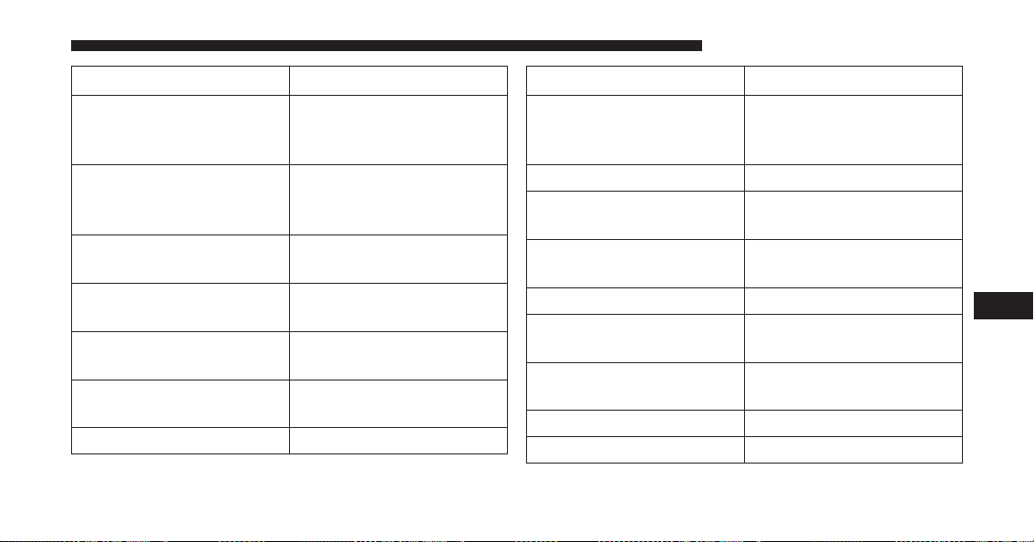
Bulb Number
Premium Bi Halogen
Projector Headlamp -
Low Beam
HIR2LL
Premium Bi Halogen
Projector Headlamp -
High Beam
9005LL
Front Turn Signal Lamp
(Premium Headlamp)
LED (Serviced at Autho-
rized Dealer)
Fog Lamp (Horizontal
shape)
9145
Fog Lamp (Vertical
shape)
9006
Center High Mounted
Stop Lamp (CHMSL)
921K
Rear Cargo Lamp 921
Bulb Number
LED Center High
Mounted Stop Lamp
(CHMSL)/Cargo Lamp
LED (Serviced at Autho-
rized Dealer)
Cab Roof Marker Lamps 194NA
Base Rear Tail/Turn and
Stop Lamp
3157K
Premium Rear Tail/Turn
and Stop Lamp
LED (Serviced at Autho-
rized Dealer)
Premium Backup Lamp 7440/W21W
Rear Lamp Bar ID
Marker Lamp
194
Side Marker Lamps
(Dual Rear Wheels)
194
Backup Lamp 921
Rear License Plate Lamp 194
7
MAINTAINING YOUR VEHICLE 823

BULB REPLACEMENT
NOTE: Lens fogging can occur under certain atmo-
spheric conditions. This will usually clear as atmospheric
conditions change to allow the condensation to change
back into a vapor. Turning the lamps on will usually
accelerate the clearing process.
Base Quad / Premium Bi-Halogen: Low Beam
Headlamp, High Beam Headlamp, Front Park And
Turn — If Equipped
1. Open the hood.
2. Disconnect and isolate the negative battery cable.
3. Remove the six plastic push-in fasteners that secure
the upper radiator seal to the grille support and both
fender ledges.
4. Remove the two plastic push-in rivets that secure the
upper radiator seal to the radiator.
5. Remove the upper radiator seal from the vehicle.
6. Remove the two headlamp assembly attachment
screws.
Headlamp Assembly Attachment Screw Locations
824 MAINTAINING YOUR VEHICLE

7. Reach into the front wheel house ahead of the front
wheel, remove the fastener, and lift the cover over the
access hole in the front of the wheel house splash
shield. Access to the rear of the lamp can be gained
through this access hole.
8. Reach through the access hole of the wheel house
splash shield and lift the slide lock upward far enough
to disengage it from the lock post on the back of the
front lamp unit housing.
9. Remove the headlamp assembly. Grasp the outboard
edge of the lamp and pull it straight forward to
disengage the ball stud from the plastic grommet.
10. Disconnect the wiring harness connectors from the
bulb socket.
Slide Lock
7
MAINTAINING YOUR VEHICLE 825
11. Replace bulb(s) as necessary.
CAUTION!
•
Do not contaminate the bulb glass by touching it
with your fingers or by allowing it to contact other
oily surfaces. Shortened bulb life will result.
• Always use the correct bulb size and type for
replacement. An incorrect bulb size or type may
overheat and cause damage to the lamp, the bulb
socket, or the lamp wiring.
NOTE: There are access covers over both headlamp bulb
access holes in the quad front lamp unit housing (if
equipped). These covers MUST be reinstalled after the
bulb has been replaced.
Fog Lamps — If Equipped
1. Reach under and behind the front bumper to access
the back of the front fog lamp housing.
2. Disconnect the fog lamp wiring harness connector
from the fog lamp bulb.
3. Rotate the bulb counterclockwise ¼ turn to unlock the
bulb from the housing.
4. Pull the bulb straight out from the housing.
CAUTION!
Do not contaminate the bulb glass by touching it
with your fingers or by allowing it to contact other
oily surfaces. Shortened bulb life will result.
826 MAINTAINING YOUR VEHICLE

Rear Tail/Stop, Turn Signal And Backup Lamps
1. Remove the two screws that pass through the bed
sheetmetal.
2. Pull the outboard side of the lamp rearward far
enough to unsnap the two receptacles on the outboard
side of the lamp housing from the two plastic snap
post retainers in the outer box side panel.
3. Disconnect the wiring harness connectors from the
bulb socket.
Tail Lamp Screw Locations
Pulling Out The Tail Lamp
7
MAINTAINING YOUR VEHICLE 827
4. Rotate the bulb socket counterclockwise 1/4 turn to
unlock it from the housing.
5. Pull the bulb straight out of the socket.
CAUTION!
Do not contaminate the bulb glass by touching it
with your fingers or by allowing it to contact other
oily surfaces. Shortened bulb life will result.
6. Reverse the procedure to install the bulb and housing.
Center High-Mounted Stoplamp (CHMSL) With
Cargo Lamp
1. Remove the two screws holding the housing/lens to
the body as shown.
2. Separate the connector holding the housing and wir-
ing harness to the body.
CHMSL Mounting Screw Locations
828 MAINTAINING YOUR VEHICLE

3. Turn the desired bulb socket ¼ turn and remove the
socket and bulb from housing.
4. Pull the desired bulb straight from the socket.
CHMSL Connector Location
CHMSL Bulb And Socket
7
MAINTAINING YOUR VEHICLE 829
CAUTION!
Do not contaminate the bulb glass by touching it
with your fingers or by allowing it to contact other
oily surfaces. Shortened bulb life will result.
• Outside Bulbs: Cargo Lamps
• Inside Bulb: Center High-Mounted Stop Lamp
5. Reverse the procedure for installation of bulbs and
housing.
Cab Top Clearance Lamps — If Equipped
1. Remove the two screws from the top of the lamp.
Removing Rear Screw From Clearance Lamp
830 MAINTAINING YOUR VEHICLE

2. Rotate the bulb socket ¼ turn and pull it from the lamp
assembly.
3. Pull the bulb straight from it’s socket and replace.
Removing Bulb Socket From Clearance Lamp
Removing The Bulb From The Bulb Socket
7
MAINTAINING YOUR VEHICLE 831

Rear Lamp Bar ID Marker (Dual Rear Wheels) — If
Equipped
1. Loosen the two screws and the housing to gain access
to the bulb sockets.
2. Turn the socket ¼ turn counterclockwise to access the
bulb.
3. Pull the bulb straight out from the socket.
4. Reverse the procedure for installation of the bulbs and
housing.
Screw Locations
832 MAINTAINING YOUR VEHICLE

Side Marker Lamps (Dual Rear Wheels) — If
Equipped
1. Push rearward on the side marker lamp assembly.
2. Pull the entire assembly from the fender.
3. Turn the socket ¼ turn counterclockwise and remove
from assembly to access the bulb.
4. Pull the bulb straight out from socket.
5. Reverse the procedure for installation of the bulbs and
housing.
Side Marker Lamp Locations
7
MAINTAINING YOUR VEHICLE 833

FLUID CAPACITIES
U.S. Metric
Fuel (Approximate)
1500 Regular Cab Shortbed/Crew Quad Cab Models 26 Gallons 98 Liters
1500 Regular Cab Longbed/Crew Quad Cab Models (Optional) 32 Gallons 121 Liters
2500/3500 Shortbed Models 31 Gallons 117 Liters
2500/3500 Longbed Models 32 Gallons 121 Liters
Engine Oil With Filter
3.6L Engine (We recommend you use SAE 5W-20, API Certified) 6 Quarts 5.6 Liters
5.7L Engines (We recommend you use SAE 5W-20, API Certified) 7 Quarts 6.6 Liters
5.7L Engine (We recommend you use SAE 5W-30, API Certified),
for 2500/3500 trucks operating under a gross combined weight
rating greater than 14,000 lbs (6 350 kg).
7 Quarts 6.6 Liters
6.4L Engines (We recommend you use SAE 0W-40 engine oil
meeting the requirements of FCA US Material Standard MS-12633
for use in all operating temperatures.)
7 Quarts 6.6 Liters
834 MAINTAINING YOUR VEHICLE
U.S. Metric
Cooling System
3.6L Engine (We recommend you use MOPAR® Antifreeze/
Coolant 10 Year/150,000 Mile Formula that meets the require-
ments of FCA Material Standard MS.90032.)
13.7 Quarts 13 Liters
5.7L Engine – 1500 Models (We recommend you use MOPAR®
Antifreeze/Coolant 10 Year/150,000 Mile Formula that meets the
requirements of FCA Material Standard MS.90032.)
18.3 Quarts 17.3 Liters
5.7L Engine – 2500/3500 Models (We recommend you use
MOPAR® Antifreeze/Coolant 10 Year/150,000 Mile Formula that
meets the requirements of FCA Material Standard MS.90032.)
18.3 Quarts 17.3 Liters
6.4 Liter Engine – 2500/3500 Models (We recommend you use
MOPAR® Antifreeze/Coolant 10 Year/150,000 Mile Formula that
meets the requirements of FCA Material Standard MS.90032.)
16.6 Quarts 15.7 Liters
7
MAINTAINING YOUR VEHICLE 835

FLUIDS, LUBRICANTS, AND GENUINE PARTS
Engine
Component Fluid, Lubricant, or Genuine Part
Engine Coolant We recommend you use MOPAR® Antifreeze/Coolant
10 Year/150,000 Mile Formula OAT (Organic Additive
Technology).
Engine Oil – 3.6L Engine We recommend you use API Certified SAE 5W-20
Engine Oil, meeting the requirements of FCA US Mate-
rial Standard MS-6395 such as MOPAR®, Pennzoil®,
and Shell Helix®. Refer to your engine oil filler cap for
correct SAE grade.
MOPAR® SAE 5W-30 engine oil approved to FCA US
Material Standard MS-6395 may be used when SAE
5W-20 engine oil meeting MS-6395 is not available.
836 MAINTAINING YOUR VEHICLE

Component Fluid, Lubricant, or Genuine Part
Engine Oil – 5.7L Engine We recommend you use API Certified SAE 5W-20
Engine Oil, meeting the requirements of FCA US Mate-
rial Standard MS-6395 such as MOPAR®, Pennzoil®,
and Shell Helix®. Refer to your engine oil filler cap for
correct SAE grade.
Engine Oil – 5.7L Engine 2500/3500 trucks operating
under a gross combined weight rating greater than
14,000 lbs/(6,350 kg.)
We recommend you use API Certified SAE 5W-30
Engine Oil, meeting the requirements of FCA US Mate-
rial Standard MS-6395 such as MOPAR®, Pennzoil®,
Shell Helix® or equivalent. Refer to your engine oil filler
cap for correct SAE grade.
Engine Oil – 6.4L For best performance and maximum protection under
all types of operating conditions, the manufacturer only
recommends full synthetic engine oils that meet the
American Petroleum Institute (API) categories of SN.
The manufacturer recommends the use of Pennzoil
Ultra™ 0W-40 or equivalent MOPAR® engine oil meet-
ing the requirements of FCA US Material Standard
MS-12633 for use in all operating temperatures.
7
MAINTAINING YOUR VEHICLE 837
Component Fluid, Lubricant, or Genuine Part
Engine Oil Filter We recommend you use MOPAR® brand Engine Oil
Filters.
Spark Plugs We recommend you use MOPAR® Spark Plugs.
Fuel Selection – 3.6L Engine 87 Octane, 0-15% Ethanol.
Fuel Selection – 3.6L Flex Fuel (E-85) Engine – If
Equipped
87 Octane, Up To 85% Ethanol.
Fuel Selection – 5.7L/6.4L Engines 89 Octane Recommended - 87 Octane Acceptable, 0-15%
Ethanol.
838 MAINTAINING YOUR VEHICLE
CAUTION!
• Mixing of engine coolant (antifreeze) other than
specified Organic Additive Technology (OAT) en-
gine coolant (antifreeze), may result in engine
damage and may decrease corrosion protection.
Organic Additive Technology (OAT) engine cool-
ant is different and should not be mixed with
Hybrid Organic Additive Technology (HOAT) en-
gine coolant (antifreeze) or any “globally compat-
ible” coolant (antifreeze). If a non-OAT engine
coolant (antifreeze) is introduced into the cooling
system in an emergency, the cooling system will
need to be drained, flushed, and refilled with fresh
OAT coolant (conforming to MS.90032), by an au-
thorized dealer as soon as possible.
• Do not use water alone or alcohol-based engine
coolant (antifreeze) products. Do not use additional
(Continued)
CAUTION! (Continued)
rust inhibitors or antirust products, as they may not
be compatible with the radiator engine coolant and
may plug the radiator.
• This vehicle has not been designed for use with
propylene glycol-based engine coolant (antifreeze).
Use of propylene glycol-based engine coolant (an-
tifreeze) is not recommended.
7
MAINTAINING YOUR VEHICLE 839

Chassis
Component Fluid, Lubricant, or Genuine Part
Automatic Transmission – Eight-Speed Automatic Use only MOPAR® ZF 8&9 Speed ATF™ Automatic
Transmission Fluid, or equivalent. Failure to use the
correct fluid may affect the function or performance of
your transmission.
Automatic Transmission – Six-Speed Automatic with
Gasoline Engine (For Diesel Engine see Diesel Supple-
ment)
Use only ATF+4® Automatic Transmission Fluid. Fail-
ure to use ATF+4® fluid may affect the function or
performance of your transmission. We recommend
MOPAR® ATF+4® fluid.
Transfer Case We recommend you use MOPAR® BW44–44 Transfer
Case Fluid.
Front Axle – 1500 Four-Wheel Drive Models We recommend you use MOPAR® GL-5 Synthetic Axle
Lubricant SAE 75W-85.
840 MAINTAINING YOUR VEHICLE
Component Fluid, Lubricant, or Genuine Part
Rear Axle – 1500 Models We recommend you use MOPAR® Synthetic Gear Lu-
bricant SAE 75W-140 (MS-8985). Limited-Slip Rear Ax-
les require the addition of 5 oz. (148 ml) MOPAR®
Limited Slip Additive (MS-10111).
Front and Rear Axle – 2500/3500 Models We recommend you use SAE 75W-85 HD Ram GL-5
Synthetic Axle Lubricant. Limited slip additive is not
required for Limited-Slip Rear Axles.
Brake Master Cylinder We recommend you use MOPAR® DOT 3. If DOT 3
brake fluid is not available, then DOT 4 is acceptable.
Power Steering Reservoir – 2500/3500 Models We recommend you use MOPAR® Power Steering Fluid
+4 or MOPAR® ATF+4® Automatic Transmission Fluid.
7
MAINTAINING YOUR VEHICLE 841



MAINTENANCE SCHEDULE
Your vehicle is equipped with an automatic oil change
indicator system. The oil change indicator system will
remind you that it is time to take your vehicle in for
scheduled maintenance.
Based on engine operation conditions, the oil change
indicator message will illuminate. This means that ser-
vice is required for your vehicle. Operating conditions
such as frequent short-trips, trailer tow, extremely hot or
cold ambient temperatures, and E85 fuel usage will
influence when the “Oil Change Required” message is
displayed. Severe Operating Conditions can cause the
change oil message to illuminate as early as 3,500 miles
(5,600 km) since last reset. Have your vehicle serviced as
soon as possible, within the next 500 miles (805 km).
Your authorized dealer will reset the oil change indicator
message after completing the scheduled oil change. If a
scheduled oil change is performed by someone other
than your authorized dealer, the message can be reset by
referring to the steps described under “Electronic Vehicle
Information Center (EVIC)” or “Driver Information Dis-
play (DID)” in “Understanding Your Instrument Panel”
for further information.
1500 Models Only
NOTE: Under no circumstances should oil change inter-
vals exceed 10,000 miles (16,000 km), twelve months or
350 hours of engine run time, whichever comes first. The
350 hours of engine run or idle time is generally only a
concern for fleet customers.
2500 – 3500 Models Only
NOTE: Under no circumstances should oil change inter-
vals exceed 8,000 miles (13,000 km), twelve months or 350
hours of engine run time, whichever comes first. The 350
hours of engine run or idle time is generally only a
concern for fleet customers.
844 MAINTENANCE SCHEDULES

Severe Duty All Models
NOTE: Change Engine Oil at 4,000 miles (6,500 km) if the
vehicle is operated in a dusty and off road environment
or is operated predominantly at idle or only very low
engine RPM’s. This type of vehicle use is considered
Severe Duty.
Once A Month Or Before A Long Trip:
• Check engine oil level
• Check windshield washer fluid level
• Check tire pressure and look for unusual wear or
damage. Rotate tires at the first sign of irregular wear,
even if it occurs before the oil indicator system turns
on.
• Check the fluid levels of the coolant reservoir, brake
master cylinder, power steering (2500/3500 Models
Only) and automatic transmission (six-speed only)
and fill as needed
• Check function of all interior and exterior lights
Maintenance Chart
Required Maintenance
Refer to the Maintenance Schedules on the following
pages for required maintenance.
8
MAINTENANCE SCHEDULES 845
At Every Oil Change Interval As Indicated By Oil
Change Indicator System:
• Change oil and filter.
• Rotate the tires. Rotate at the first sign of irregu-
lar wear, even if it occurs before the oil indicator
system turns on.
• Inspect battery and clean and tighten terminals as
required.
• Inspect automatic transmission fluid if equipped
with dipstick.
• Inspect brake pads, shoes, rotors, drums, hoses
and park brake.
At Every Oil Change Interval As Indicated By Oil
Change Indicator System:
• Inspect engine cooling system protection and
hoses.
• Inspect exhaust system.
• Inspect engine air cleaner if using in dusty or
off-road conditions.
• Lube the front drive shaft fitting (2500/3500 (4x4)
models only).
846 MAINTENANCE SCHEDULES
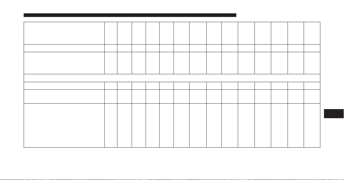
Mileage or time passed
(whichever comes first)
20,000
30,000
40,000
50,000
60,000
70,000
80,000
90,000
100,000
110,000
120,000
130,000
140,000
150,000
Or Years: 2 3 4 5 6 7 8 9 10 11 12 13 14 15
Or Kilometers:
32,000
48,000
64,000
80,000
96,000
112,000
128,000
144,000
160,000
176,000
192,000
208,000
224,000
240,000
Additional Inspections
Inspect the CV/Universal joints. X X X X X
Inspect front suspension, tie rod
ends, and replace if necessary.
XXX X X X X
1500 Models:
Inspect the front and rear axle
surfaces. If gear oil leakage is
suspected, check the fluid level.
If using your vehicle for police,
taxi, fleet, off-road or frequent
trailer towing, change axle fluid.
XX X X X
8
MAINTENANCE SCHEDULES 847

Mileage or time passed
(whichever comes first)
20,000
30,000
40,000
50,000
60,000
70,000
80,000
90,000
100,000
110,000
120,000
130,000
140,000
150,000
Or Years: 2 3 4 5 6 7 8 9 10 11 12 13 14 15
Or Kilometers:
32,000
48,000
64,000
80,000
96,000
112,000
128,000
144,000
160,000
176,000
192,000
208,000
224,000
240,000
2500/3500 Models:
Inspect the front and rear axle
surfaces. If gear oil leakage is
suspected, check the fluid level.
If using your vehicle for police,
taxi, fleet, off-road or frequent
trailer towing, change axle fluid.
XXX X X X X
Inspect the brake linings, replace
as necessary.
XXX X X X X
Adjust parking brake as neces-
sary.
XXX X X X X
Inspect transfer case fluid. X X X
848 MAINTENANCE SCHEDULES
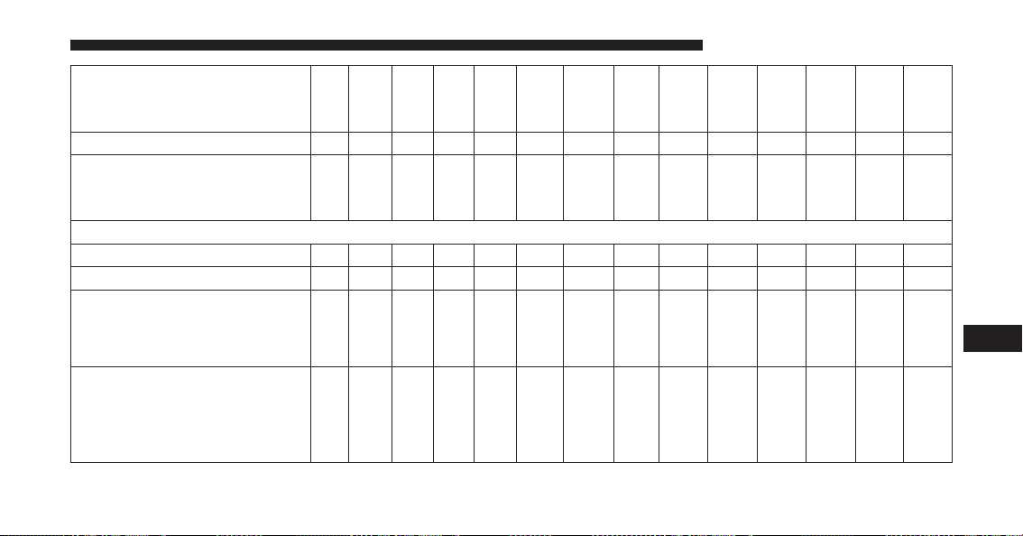
Mileage or time passed
(whichever comes first)
20,000
30,000
40,000
50,000
60,000
70,000
80,000
90,000
100,000
110,000
120,000
130,000
140,000
150,000
Or Years: 2 3 4 5 6 7 8 9 10 11 12 13 14 15
Or Kilometers:
32,000
48,000
64,000
80,000
96,000
112,000
128,000
144,000
160,000
176,000
192,000
208,000
224,000
240,000
Additional Maintenance
Replace engine air filter. X X X X X
Replace spark plugs. ** X
Flush and replace the engine
coolant at 10 years or 150,000
miles (240,000 km) whichever
comes first.
XX
Change automatic transmission
fluid and filter(s) (six-speed auto-
matic only), if using your vehicle
for police, taxi, fleet, or frequent
trailer towing.
X
8
MAINTENANCE SCHEDULES 849

Mileage or time passed
(whichever comes first)
20,000
30,000
40,000
50,000
60,000
70,000
80,000
90,000
100,000
110,000
120,000
130,000
140,000
150,000
Or Years: 2 3 4 5 6 7 8 9 10 11 12 13 14 15
Or Kilometers:
32,000
48,000
64,000
80,000
96,000
112,000
128,000
144,000
160,000
176,000
192,000
208,000
224,000
240,000
Change automatic transmission
fluid and filter(s) (six-speed auto-
matic only).
X
Inspect the transfer case fluid,
change for any of the following:
police, taxi, fleet, or frequent
trailer towing.
XX
Change the transfer case fluid. X
Inspect and replace PCV valve if
necessary.
X
** The spark plug change interval is mileage based only,
yearly intervals do not apply.
850 MAINTENANCE SCHEDULES
WARNING!
• You can be badly injured working on or around a
motor vehicle. Do only service work for which you
have the knowledge and the right equipment. If
you have any doubt about your ability to perform a
service job, take your vehicle to a competent me-
chanic.
• Failure to properly inspect and maintain your ve-
hicle could result in a component malfunction and
effect vehicle handling and performance. This
could cause an accident.
8
MAINTENANCE SCHEDULES 851


IF YOU NEED CONSUMER ASSISTANCE
CONTENTS
䡵 SUGGESTIONS FOR OBTAINING SERVICE FOR
YOUR VEHICLE .......................855
▫ Prepare For The Appointment.............855
▫ Prepare A List ........................855
▫ Be Reasonable With Requests .............855
䡵 IF YOU NEED ASSISTANCE ..............855
▫ FCA USA LLC Customer Center ...........856
▫ FCA Canada Inc. Customer Center .........856
▫ In Mexico Contact .....................857
▫ Customer Assistance For The Hearing Or Speech
Impaired (TDD/TTY)...................857
▫ Service Contract ......................857
䡵 WARRANTY INFORMATION .............858
䡵 MOPAR®PARTS.......................859
䡵 REPORTING SAFETY DEFECTS ............859
▫ In The 50 United States And Washington,
D.C. ...............................859
▫ In Canada...........................859
䡵 PUBLICATION ORDER FORMS ............860
9


SUGGESTIONS FOR OBTAINING SERVICE FOR
YOUR VEHICLE
Prepare For The Appointment
If you are having warranty work done, be sure to have
the right papers with you. Take your warranty folder. All
work to be performed may not be covered by the
warranty. Discuss additional charges with the service
manager. Keep a maintenance log of your vehicle’s
service history. This can often provide a clue to the
current problem.
Prepare A List
Make a written list of your vehicle’s problems or the
specific work you want done. If you’ve had an accident
or work done that is not on your maintenance log, let the
service advisor know.
Be Reasonable With Requests
If you list a number of items and you must have your
vehicle by the end of the day, discuss the situation with
the service advisor and list the items in order of priority.
At many authorized dealers, you may obtain a rental
vehicle at a minimal daily charge. If you need a rental, it
is advisable to make these arrangements when you call
for an appointment.
IF YOU NEED ASSISTANCE
The manufacturer and its authorized dealer are vitally
interested in your satisfaction. We want you to be happy
with our products and services.
Warranty service must be done by an authorized dealer.
We strongly recommend that you take the vehicle to an
authorized dealer. They know your vehicle the best, and
are most concerned that you get prompt and high quality
service. The manufacturer’s authorized dealer have the
9
IF YOU NEED CONSUMER ASSISTANCE 855

facilities, factory-trained technicians, special tools, and
the latest information to ensure the vehicle is fixed
correctly and in a timely manner.
This is why you should always talk to an authorized
dealer service manager first. Most matters can be re-
solved with this process.
• If for some reason you are still not satisfied, talk to the
general manager or owner of the authorized dealer.
They want to know if you need assistance.
• If an authorized dealer is unable to resolve the con-
cern, you may contact the manufacturer’s customer
center.
Any communication to the manufacturer’s customer cen-
ter should include the following information:
• Owner’s name and address
• Owner’s telephone number (home and office)
• Authorized dealer name
• Vehicle Identification Number (VIN)
• Vehicle delivery date and mileage
FCA USA LLC Customer Center
P.O. Box 21–8004
Auburn Hills, MI 48321–8004
Phone: (866) 726-4636
FCA Canada Inc. Customer Center
P.O. Box 1621
Windsor, Ontario N9A 4H6
Phone: (800) 465-2001 English / (800) 387-9983 French
856 IF YOU NEED CONSUMER ASSISTANCE

In Mexico Contact
Av. Prolongacion Paseo de la Reforma, 1240
Sante Fe C.P. 05109
Mexico, D. F.
In Mexico City: 5081-7568
Outside Mexico City: 1-800-505-1300
Customer Assistance For The Hearing Or Speech
Impaired (TDD/TTY)
To assist customers who have hearing difficulties, the
manufacturer has installed special TDD (Telecommuni-
cation Devices for the Deaf) equipment at its customer
center. Any hearing or speech impaired customer, who
has access to a TDD or a conventional teletypewriter
(TTY) in the United States, can communicate with the
manufacturer by dialing 1-800-380-CHRY.
Canadian residents with hearing difficulties that require
assistance can use the special needs relay service offered
by Bell Canada. For TTY teletypewriter users, dial 711
and for Voice callers, dial 1-800-855-0511 to connect with
a Bell Relay Service operator.
Service Contract
You may have purchased a service contract for a vehicle
to help protect you from the high cost of unexpected
repairs after the manufacturer’s New Vehicle Limited
Warranty expires. The manufacturer stands behind only
the manufacturer’s service contracts. If you purchased a
manufacturer’s service contract, you will receive Plan
Provisions and an Owner Identification Card in the mail
within three weeks of the vehicle delivery date. If you
have any questions about the service contract, call the
manufacturer’s Service Contract National Customer
Hotline at 1-800-521-9922 (Canadian residents, call (800)
465-2001 English / (800) 387-9983 French).
9
IF YOU NEED CONSUMER ASSISTANCE 857
The manufacturer will not stand behind any service
contract that is not the manufacturer’s service contract. It
is not responsible for any service contract other than the
manufacturer’s service contract. If you purchased a ser-
vice contract that is not a manufacturer’s service contract,
and you require service after the manufacturer’s New
Vehicle Limited Warranty expires, please refer to the
contract documents, and contact the person listed in
those documents.
We appreciate that you have made a major investment
when you purchased the vehicle. An authorized dealer
has also made a major investment in facilities, tools, and
training to assure that you are absolutely delighted with
the ownership experience. You will be pleased with their
sincere efforts to resolve any warranty issues or related
concerns.
WARNING!
Engine exhaust (internal combustion engines only),
some of its constituents, and certain vehicle compo-
nents contain, or emit, chemicals known to the State
of California to cause cancer and birth defects, or
other reproductive harm. In addition, certain fluids
contained in vehicles and certain products of compo-
nent wear contain, or emit, chemicals known to the
State of California to cause cancer and birth defects,
or other reproductive harm.
WARRANTY INFORMATION
See the Warranty Information Booklet, located on the
DVD, for the terms and provisions of FCA US LLC
warranties applicable to this vehicle and market.
858 IF YOU NEED CONSUMER ASSISTANCE

MOPAR® PARTS
MOPAR® fluids, lubricants, parts, and accessories are
available from an authorized dealer. They are recom-
mended for your vehicle in order to help keep the vehicle
operating at its best.
REPORTING SAFETY DEFECTS
In The 50 United States And Washington, D.C.
If you believe that your vehicle has a defect that could
cause a crash or cause injury or death, you should
immediately inform the National Highway Traffic Safety
Administration (NHTSA) in addition to notifying the
manufacturer.
If NHTSA receives similar complaints, it may open an
investigation, and if it finds that a safety defect exists in
a group of vehicles, it may order a recall and remedy
campaign. However, NHTSA cannot become involved in
individual problems between you, your authorized
dealer, and the manufacturer.
To contact NHTSA, you may either call the Auto Safety
Hotline toll free at 1-888-327-4236 (TTY: 1-800-424-9153),
or go to http://www.safercar.gov; or write to: Adminis-
trator, NHTSA, 1200 New Jersey Avenue, SE., West
Building, Washington, D.C. 20590.
You can also obtain other information about motor
vehicle safety from http://www.safercar.gov.
In Canada
If you believe that your vehicle has a safety defect, you
should contact the Customer Service Department imme-
diately. Canadian customers who wish to report a safety
defect to the Canadian government should contact Trans-
port Canada, Motor Vehicle Defect Investigations and
Recalls at 1-800-333-0510 or go to http://www.tc.gc.ca/
roadsafety/
9
IF YOU NEED CONSUMER ASSISTANCE 859

PUBLICATION ORDER FORMS
To order the following manuals, you may use either the
website or the phone numbers listed below. Visa, Mas-
tercard, American Express, and Discover orders are ac-
cepted. If you prefer mailing your payment, please call
for an order form.
NOTE: A street address is required when ordering
manuals (no P.O. Boxes).
Service Manuals
These comprehensive Service Manuals provide the infor-
mation that students and professional technicians need in
diagnosing/troubleshooting, problem solving, maintain-
ing, servicing, and repairing FCA US LLC vehicles. A
complete working knowledge of the vehicle, system,
and/or components is written in straightforward lan-
guage with illustrations, diagrams, and charts.
Diagnostic Procedure Manuals
Diagnostic Procedure Manuals are filled with diagrams,
charts and detailed illustrations. These practical manuals
make it easy for students and technicians to find and fix
problems on computer-controlled vehicle systems and
features. They show exactly how to find and correct
problems the first time, using step-by-step troubleshoot-
ing and drivability procedures, proven diagnostic tests
and a complete list of all tools and equipment.
Owner’s Manuals
These Owner’s Manuals have been prepared with the
assistance of service and engineering specialists to ac-
quaint you with specific FCA US LLC vehicles. Included
are starting, operating, emergency and maintenance pro-
cedures as well as specifications, capabilities and safety
tips.
860 IF YOU NEED CONSUMER ASSISTANCE

Call toll free at:
• 1-800-890-4038 (U.S.)
• 1-800-387-1143 (Canada)
Or
Visit us on the Worldwide Web at:
• www.techauthority.com
DEPARTMENT OF TRANSPORTATION UNIFORM
TIRE QUALITY GRADES
The following tire grading categories were established by
the National Highway Traffic Safety Administration. The
specific grade rating assigned by the tire’s manufacturer
in each category is shown on the sidewall of the tires on
your vehicle.
All passenger car tires must conform to Federal safety
requirements in addition to these grades.
Treadwear
The Treadwear grade is a comparative rating, based on
the wear rate of the tire when tested under controlled
conditions on a specified government test course. For
example, a tire graded 150 would wear one and one-half
times as well on the government course as a tire graded
100. The relative performance of tires depends upon the
actual conditions of their use, however, and may depart
significantly from the norm due to variations in driving
habits, service practices, and differences in road charac-
teristics and climate.
Traction Grades
The Traction grades, from highest to lowest, are AA, A, B,
and C. These grades represent the tire’s ability to stop on
wet pavement, as measured under controlled conditions
on specified government test surfaces of asphalt and
concrete. A tire marked C may have poor traction perfor-
mance.
9
IF YOU NEED CONSUMER ASSISTANCE 861
WARNING!
The traction grade assigned to this tire is based on
straight-ahead braking traction tests, and does not
include acceleration, cornering, hydroplaning, or
peak traction characteristics.
Temperature Grades
The temperature grades are A (the highest), B, and C,
representing the tire’s resistance to the generation of heat
and its ability to dissipate heat, when tested under
controlled conditions on a specified indoor laboratory
test wheel. Sustained high temperature can cause the
material of the tire to degenerate and reduce tire life, and
excessive temperature can lead to sudden tire failure. The
grade C corresponds to a level of performance, which all
passenger car tires must meet under the Federal Motor
Vehicle Safety Standard No. 109. Grades B and A repre-
sent higher levels of performance on the laboratory test
wheel, than the minimum required by law.
WARNING!
The temperature grade for this tire is established for
a tire that is properly inflated and not overloaded.
Excessive speed, under-inflation, or excessive load-
ing, either separately or in combination, can cause
heat buildup and possible tire failure.
862 IF YOU NEED CONSUMER ASSISTANCE

INDEX
10

Adding Engine Coolant (Antifreeze) ............791
Adding Fuel .............................655
Adjustable Pedals .........................184
Airbag.................................67
Air Bag
Advance Front Air Bag ....................67
Air bag Operation .......................70
Air Bag Warning Light ....................78
Enhanced Accident Response ................77
Event Data Recorder (EDR) .................80
FrontAirBag...........................67
If A Deployment Occurs ...................76
Knee Impact Bolsters .....................71
Maintaining Your Air Bag System ............80
Side Air Bags ...........................71
Air bag Deployment ........................67
Air bag Light ......................78, 116, 287
Air bag Maintenance........................80
Air Cleaner, Engine (Engine Air Cleaner Filter) . . . .773
Air Conditioner Maintenance .................779
Air Conditioning ......................400, 405
Air Conditioning Controls................400, 405
Air Conditioning, Operating Tips...........419, 422
Air Conditioning Refrigerant ..........779, 780, 781
Air Conditioning System ..........400, 405, 418, 779
Air Pressure, Tires .....................621, 632
Air Suspension ...........................527
Alarm Light .............................287
Alarm, Panic .............................28
Alarm (Security Alarm) ......................21
Alarm System (Security Alarm) ................21
Alterations/Modifications, Vehicle ...............7
Antifreeze (Engine Coolant)...............790, 834
Disposal ..............................793
Anti-Lock Brake System (ABS) ................593
Anti-Lock Warning Light.................287, 594
Appearance Care .........................803
Ashtray ................................231
864 INDEX

Auto Down Power Windows ..................47
Automatic Door Locks ......................39
Automatic Headlights ......................167
Automatic High Beams .....................169
Automatic Temperature Control (ATC) ..........418
Automatic Transmission .................463, 803
Adding Fluid .......................802, 803
Fluid and Filter Changes ..................803
Fluid Change ..........................803
Fluid Level Check ................799, 800, 801
Fluid Type .........................799, 840
Shifting ...........................472, 485
Special Additives .......................800
Axle Fluid ...........................798, 840
Axle Lubrication ..........................798
Back-Up Camera..........................208
Bar, Stabilizer/Sway System..................542
Battery.................................778
Keyless Transmitter Replacement (RKE) ........30
Belts, Seat...............................116
Body Builders Guide ........................6
Body Mechanism Lubrication .................781
B-Pillar Location ..........................615
Brake Assist System .......................595
Brake Control System, Electronic ..............593
Brake Fluid ..........................796, 840
Brake System .........................592, 796
Anti-Lock (ABS) ........................593
Fluid Check ...........................796
Master Cylinder ........................796
Parking ..............................590
Warning Light .........................287
10
INDEX 865

Brake/Transmission Interlock .................462
Bulb Replacement......................822, 824
Bulbs, Light ..........................118,822
Cab Top Clearance Lights ...................830
Camera, Rear ............................208
Camper ................................267
Capacities, Fluid ..........................834
Caps, Filler
Oil (Engine) ...........................772
Power Steering .........................589
Radiator (Coolant Pressure) ................792
Carbon Monoxide Warning ...............115,651
Cargo Light .............................175
Car Washes .............................804
Cellular Phone ...........................398
Center High Mounted Stop Light ..............828
Center Seat Storage Compartment .............239
Certification Label.........................658
Chart, Tire Sizing .........................610
Check Engine Light (Malfunction Indicator
Light) ............................287, 766
Checking Your Vehicle For Safety ..............114
Checks, Safety............................114
Child Restraint ............................82
Child Restraints
Booster Seats ...........................87
Child Restraints .........................82
Child Seat Installation .................100, 102
How To Stow An Unused ALR Seat Belt ........98
Infants And Child Restraints ................85
Install A LATCH-compatible Child Restraint .....97
Installing Child Restraints Using The Vehicle Seat
Belt ..................................99
866 INDEX

Locating The LATCH Anchorages ............94
Lower Anchors And Tethers For Children .......89
Older Children And Child Restraints ..........85
Seating Positions ........................88
Cigar Lighter ............................231
Clean Air Gasoline ........................648
Cleaning
Wheels ...............................806
Climate Control .......................400, 410
Automatic ............................410
Cold Weather Operation ....................453
Compact Disc (CD) Maintenance ..............397
Compact Spare Tire ........................627
Console, Overhead ........................210
Contract, Service ..........................857
Coolant Pressure Cap (Radiator Cap) ...........792
Cooling System...........................788
Adding Coolant (Antifreeze) ...............791
Coolant Capacity .......................834
Coolant Level ...................789, 793, 794
Disposal of Used Coolant .................793
Drain, Flush, and Refill ...................789
Inspection .........................793, 794
Points to Remember .....................795
Pressure Cap ..........................792
Radiator Cap ..........................792
Selection of Coolant (Antifreeze) ......790, 834, 836
Corrosion Protection .......................803
Cupholders .............................234
Customer Assistance .......................855
Customer Programmable Features .............375
10
INDEX 867

Data Recorder, Event .......................80
Daytime Running Lights ....................168
Dealer Service............................768
Defroster, Rear Window.....................245
Defroster, Windshield ...................116,403
Delay (Intermittent) Wipers ..................178
Differential, Limited-Slip ....................562
Dipsticks
Power Steering .........................589
Disabled Vehicle Towing ....................754
Disposal
Antifreeze (Engine Coolant) ................793
Door Locks
Door Locks ............................37
KeyFob...............................37
Remote ...............................37
Remote Keyless Entry (RKE) ................37
Door Locks, Automatic ......................39
Door Opener, Garage.......................212
Driving
Off-Pavement ..........................544
Off-Road .............................544
Through Flowing, Rising, or Shallow Standing
Water ................................564
Dual Rear Wheels......................636, 699
E-85 Fuel ...............................652
Electrical Power Outlets.....................225
Electric Rear Window Defrost.................245
Electronically Shifted Transfer Case. . .500, 506, 513, 520
Electronic Brake Control System ...............593
Anti-Lock Brake System ..................593
Brake Assist System .....................595
Traction Control System ...................595
868 INDEX

Electronic Range Select (ERS) ..........470, 480, 492
Electronic Speed Control (Cruise Control) ........185
Electronic Stability Control (ESC) ..............598
Electronic Vehicle Information Center (EVIC) . .208, 299
Electronic Vehicle Information Center (EVIC) . . . .299
Electronic Vehicle Information Center (EVIC) Setup
Menu ................................299
EVIC Messages .........................299
Selectable Menu Items ....................314
Emergency Brake .........................590
Emergency, In Case of
Freeing Vehicle When Stuck ................748
Hazard Warning Flasher ..................697
Jump Starting ..........................743
Tow Hooks ............................749
Emission Control System Maintenance ..........766
Engine..............................763, 764
Air Cleaner ...........................773
Block Heater ..........................459
Break-In Recommendations ................113
Compartment ..........................762
Compartment Identification .........762, 763, 764
Coolant (Antifreeze) .....................836
Exhaust Gas Caution .................115,651
Flooded, Starting .......................453
Fuel Requirements ...................647, 834
Jump Starting ..........................743
Oil ...........................769, 834, 836
Oil Filler Cap ..........................772
Oil Selection .......................770, 834
Oil Synthetic ..........................772
Overheating ...........................697
10
INDEX 869

Engine Oil Viscosity ....................771, 772
Engine Oil Viscosity Chart ...................771
Enhanced Accident Response Feature ............77
Entry System, Illuminated ....................23
Ethanol ................................648
Event Data Recorder ........................80
Exhaust Gas Caution....................115,651
Exhaust System .......................115,786
Exterior Lighting..........................166
Exterior Lights ...........................118
Filters
Air Cleaner ...........................773
Engine Oil .........................773, 836
Engine Oil Disposal .....................773
Flashers
Turn Signal .....................118,176, 287
Flat Tire Stowage ......................716, 737
Flexible Fuel Vehicles
Cruising Range .........................654
Engine Oil ............................653
Fuel Requirements ...................652, 653
Maintenance ...........................655
Replacement Parts .......................654
Starting ..............................654
Flooded Engine Starting ....................453
Fluid, Brake .............................840
Fluid Capacities ..........................834
Fluid Leaks .............................118
Fluid Level Checks
Brake ................................796
Power Steering .........................589
870 INDEX

Fluids, Lubricants and Genuine Parts ...........836
Fog Lights........................171, 287, 826
Fold Flat Load Floor .......................246
Four-Way Hazard Flasher ...................697
Four Wheel Drive .........................496
Freeing A Stuck Vehicle .....................748
Front Axle (Differential).....................798
Fuel...................................647
Adding ..............................655
Clean Air .............................648
Ethanol ..............................648
Filler Cap (Gas Cap) .....................657
Gasoline ..............................647
Methanol .............................648
Octane Rating ......................647, 836
Requirements .......................647, 834
Tank Capacity ..........................834
Fuel, Flexible ............................652
Fuses ..................................812
Garage Door Opener (HomeLink®) .........212, 220
Gas Cap (Fuel Filler Cap) ................657, 765
Gasoline, Clean Air ........................648
Gasoline (Fuel) ...........................647
Gasoline, Reformulated .....................648
Gauges
Speedometer ..........................287
Tachometer ............................287
Gear Ranges .........................473, 486
Gear Select Lever Override ..................750
General Information .......................646
Glass Cleaning ...........................809
Grocery Bag Retainer.......................244
Gross Axle Weight Rating ...................661
Gross Vehicle Weight Rating..................660
10
INDEX 871

Guide, Body Builders ........................6
GVWR .................................658
Hazard
Driving Through Flowing, Rising, or Shallow
Standing Water .........................564
Hazard Warning Flasher ....................697
Headlights ..............................824
Automatic ............................167
Cleaning .............................809
High Beam ............................177
High Beam/Low Beam Select Switch .........177
Passing ..............................177
Switch ...............................166
Head Restraints ..........................155
Heated Mirrors .......................140, 245
Heater..............................400, 405
Heater, Engine Block .......................459
High Beam/Low Beam Select (Dimmer) Switch . . . .177
Hill Descent Control .......................604
Hill Descent Control Indicator ................604
Hitches
Trailer Towing .........................668
Hoisting................................742
HomeLink® (Garage Door Opener) ............212
Hood Release ............................164
Hub Caps...............................741
Ignition .................................16
Key ...............................12, 16
Ignition Key Removal .......................16
Illuminated Entry ..........................23
Immobilizer (Sentry Key) ....................18
Inflation Pressure Tires .....................632
Information Center, Vehicle ...............299, 328
Inside Rearview Mirror ..................126, 133
Instrument Cluster ........................287
Instrument Panel and Controls ................284
872 INDEX

Instrument Panel Lens Cleaning ...............809
Integrated Trailer Brake Controls ..............674
Interior Appearance Care....................808
Interior Lights ...........................172
Intermittent Wipers (Delay Wipers).............178
Introduction ..............................4
Inverter Outlet (115V) ......................232
Jack Location .........................701, 721
Jump Starting ............................743
Key Fob
Programming Additional Key Fobs ...........20
Programming Additional Transmitters .........20
Key-In Reminder ..........................18
Keyless Enter-N-Go .....................42, 451
Keyless Enter-N-Go™ .......................42
Lock The Vehicle’s Doors ..............365, 386
Passive Entry ...........................42
Passive Entry Programming ..........42, 365, 386
Keyless Entry System .......................24
Key, Replacement ..........................19
Keys ...................................12
Key, Sentry (Immobilizer) ....................18
Lane Change and Turn Signals ................176
Lane Change Assist........................177
Lap/Shoulder Belts.........................52
Latches ................................118
Lead Free Gasoline ........................647
Leaks, Fluid .............................118
Life of Tires .............................630
Light Bulbs ..........................118,822
10
INDEX 873

Lights ..............................118,165
Airbag .........................78, 116, 287
Alarm ...............................287
Anti-Lock .............................287
Anti-Lock Warning ......................594
Automatic Headlights ....................167
Brake Assist Warning ....................602
Brake Warning .........................287
Bulb Replacement .......................824
Cap Top Clearance ......................830
Cargo ...............................175
Center Mounted Stop ....................828
Check Engine (Malfunction Indicator) .........287
Courtesy/Reading ................173, 175, 211
Daytime Running .......................168
Electronic Stability Program (ESP) Indicator .....602
Exterior ..............................118
Fog ..........................171, 287, 826
Four-Wheel Drive Indicator ................499
Hazard Warning Flasher ..................697
Headlights ............................166
High Beam ........................177, 287
High Beam Indicator .....................287
High Beam/Low Beam Select ...............177
Hill Descent Control Indicator ..............604
Illuminated Entry ........................23
Instrument Cluster ......................287
Interior .....................172, 173, 175, 211
Oil Pressure ...........................287
Passing ..............................177
Seat Belt Reminder ......................287
Security Alarm .........................287
Service ...........................822, 824
Side Marker ...........................833
Tire Pressure Monitoring (TPMS) .........287, 638
Traction Control ........................602
T
ransfer Case ..........................499
Turn Signal ..................118,176, 824, 827
874 INDEX

Warning (Instrument Cluster Description) ......287
Limited-Slip Differential .................562, 798
Loading Vehicle ..........................658
Tires ................................615
Locks ..................................37
Automatic Door .........................39
Child Protection .........................40
Door .................................37
Power Door ............................38
Low Tire Pressure System ...................638
Lubrication, Body .........................781
Lug Nuts............................698, 699
Maintenance Free Battery....................778
Maintenance Procedures ....................768
Maintenance Schedule ......................844
Malfunction Indicator Light (Check Engine).......766
Manual, Service ..........................860
Manual Transmission
Fluid Level Check .......................799
Lubricant Selection ......................840
Memory Seat ............................159
Methanol ...............................648
Mirrors ................................126
Electric Powered ........................138
Heated ...............................140
Memory ..............................159
Outside ..............................134
Rearview ..........................126, 133
Trailer Towing .........................140
Modifications/Alterations, Vehicle ...............7
Monitor, Tire Pressure System ................638
MOPAR® Parts .......................767, 859
MTBE/ETBE ............................648
Multi-Function Control Lever .................176
10
INDEX 875

Navigation System (Uconnect® gps) ............208
New Vehicle Break-In Period .................113
Occupant Restraints ........................49
Octane Rating, Gasoline (Fuel) ................647
Off-Pavement Driving (Off-Road)...........544, 566
Off-Road Driving (Off-Pavement)...........544, 566
Oil, Engine ..........................769, 836
Capacity .............................834
Change Interval ........................770
Dipstick ..............................769
Disposal ..............................773
Filter .............................773, 836
Filter Disposal .........................773
Identification Logo ......................771
Recommendation ....................770, 834
Synthetic .............................772
Viscosity .......................771, 772, 834
Oil Filter, Selection ........................773
Onboard Diagnostic System ..................765
Operating Precautions ......................765
Operator Manual (Owner’s Manual) .............4
Outside Rearview Mirrors ...................134
Overdrive ...........................482, 493
Overdrive OFF Switch ..................482, 493
Overhead Console.........................210
Overheating, Engine .......................697
Owner’s Manual (Operator Manual) ..........4,860
Paint Care ..............................803
Panic Alarm ..............................28
Parking Brake............................590
ParkSense® System, Rear ................190, 199
Passing Light ............................177
Passive Entry .............................42
Pedals, Adjustable.........................184
876 INDEX

Personal Settings ......................322, 350
Pets ...................................113
Pets, Transporting .........................113
Pickup Box .......................251, 253, 270
Placard, Tire and Loading Information ..........616
Power
Distribution Center (Fuses) ................813
Door Locks ............................38
Mirrors ..............................138
Outlet (Auxiliary Electrical Outlet) ........225, 232
Seats ................................143
Sliding Rear Window ....................246
Steering .......................587, 588, 589
Sunroof ..............................222
Windows ..............................46
Power Steering Fluid.......................840
Pregnant Women and Seat Belts ................62
Pretensioners
Seat Belts ..............................63
Programmable Electronic Features ..........322, 350
Programming Transmitters (Remote Keyless Entry) . .24
Radial Ply Tires ..........................623
Radiator Cap (Coolant Pressure Cap) ........789, 792
Radio Operation ..........................398
Radio (Sound Systems) .....................395
Rain Sensitive Wiper System .................180
Ramp Travel Index ........................545
Rear Axle (Differential) .....................798
Rear Cargo Area Utility Rails .................265
Rear ParkSense System ..................190, 199
Rear Seat, Folding .....................152, 153
Rear Window Features .....................245
Rear Window, Sliding ......................246
Reclining Rear Seats .......................151
Recorder, Event Data .......................80
10
INDEX 877

Recreational Towing .......................686
Shifting into Transfer Case Neutral (N) ........689
Shifting out of Transfer Case Neutral (N) ......692
Reformulated Gasoline .....................648
Refrigerant...........................780, 781
Reminder, Seat Belt.........................51
Remote Control
Starting System .........................34
Remote Keyless Entry (RKE)................24, 26
FCC General Information ..................33
Programming Additional Key Fobs ...........20
Programming Additional Transmitters .........20
Remote Sound System (Radio) Controls .........396
Remote Starting
Uconnect® Customer Programmable
Features ..........................367, 388
Uconnect® Settings ..................367, 388
Remote Starting System......................34
Replacement Bulbs ........................822
Replacement Keys .........................19
Replacement Parts.........................767
Replacement Tires .........................631
Reporting Safety Defects ....................859
Restraint, Head...........................155
Restraints, Child...........................82
Restraints, Occupant ........................49
Rotation, Tires ...........................635
Safety Checks Inside Vehicle..................116
Safety Checks Outside Vehicle ................118
Safety Defects, Reporting ....................859
Safety, Exhaust Gas ........................115
Safety Information, Tire .....................608
Safety Tips ..............................114
Schedule, Maintenance .....................844
Seat Belt
Lap/Shoulder Belt Operation ................55
Lap/Shoulder Belts .......................52
878 INDEX

Lap/Shoulder Belt Untwisting ...............60
Pregnant Women ........................62
Seat Belt Extender .......................62
Seat Belt Pretensioner .....................63
Seat Belt Reminder .......................51
Seat Belt System .........................49
Seat Belt Maintenance ......................810
Seat Belt Reminder .........................51
Seat Belts.............................51, 116
Child Restraint ..........................82
Extender ..............................62
Front Seat ........................51, 52, 55
Inspection ............................116
Operating Instructions ....................55
Pregnant Women ........................62
Pretensioners ...........................63
Rear Seat ..............................52
Reminder .............................287
Untwisting Procedure .....................60
Seats ...............................142, 151
Adjustment ...........................142
Easy Entry ............................162
Folding Floor ..........................246
Memory ..............................159
Power ...............................143
Rear Folding .......................152, 153
Reclining Rear .........................151
Security Alarm ............................21
Selection of Coolant (Antifreeze)...............836
SENTRY KEY®
FCC General Information ..................20
Key Programming .......................20
Sentry Key (Immobilizer) ....................18
Sentry Key Replacement .....................19
Service Assistance .........................855
Service Contract ..........................857
Service Manuals ..........................860
Settings, Personal ......................322, 350
10
INDEX 879

Shifting ................................460
Automatic Transmission ............463, 472, 485
Transfer Case ..........................498
Transfer Case, Shifting into Transfer Case
Neutral (N) ...........................689
Transfer Case, Shifting out of Transfer Case
Neutral (N) ...........................692
Shift Lever Override .......................750
Shoulder Belts ............................52
Signals, Turn ......................118,176, 287
Sliding Rear Window
Power ...............................246
Snow Chains (Tire Chains) ...................632
Snow Plow..............................682
Snow Tires ..............................625
Spare Tire ...........................627, 628
Spark Plugs .............................836
Speed Control (Cruise Control)................185
Speedometer.............................287
Stabilizer/Sway Bar System ..................542
Starting..............................34, 450
Automatic Transmission ..................451
Cold Weather ..........................453
Engine Fails to Start .....................453
Remote ...............................34
Starting Procedures (Gas Engines) .............450
Steering
Power .........................587, 588, 589
Wheel, Heated .........................182
Wheel, Tilt ............................181
Steering Wheel Audio Controls ...............396
Steering Wheel Mounted Sound System Controls . . .396
Storage Compartment, Center Seat .............239
Storage, Vehicle .......................420, 822
Storing Your Vehicle .......................822
Sun Roof ...............................222
Supplemental Restraint System - Airbag ..........67
Supplemental Tire Pressure Information .........632
880 INDEX

Suspension, Air...........................527
Sway Control, Trailer.......................604
Synthetic Engine Oil .......................772
System, Remote Starting .....................34
Tachometer..............................287
Tailgate ................................267
Temperature Control, Automatic (ATC) ..........418
Tilt Steering Column .......................181
Tip Start................................451
Tire and Loading Information Placard . . . .615, 616, 632
Tire Markings ............................608
Tires............................118,620, 861
Aging (Life of Tires) .....................630
Air Pressure ...........................620
Chains ...............................632
Compact Spare .........................627
Dual .............................636, 699
General Information .....................620
High Speed ...........................623
Inflation Pressures .......................621
Life of Tires ...........................630
Load Capacity ......................615, 616
Pressure Monitor System (TPMS) ............638
Pressure Warning Light ...................287
Quality Grading ........................861
Radial ...............................623
Replacement ...........................631
Rotation ..............................635
Safety ............................608, 620
Sizes ................................610
Snow Tires ............................625
Spinning .............................629
Tread Wear Indicators ....................629
Tire Safety Information .....................608
Tongue Weight/Trailer Weight ................669
T
onneau Cover ...........................810
Tonneau Cover Cleaning ....................810
10
INDEX 881

Torque Converter Clutch .................484, 495
Tow Hooks, Emergency .....................749
Towing .............................660, 754
Disabled Vehicle ........................754
Guide ...............................669
Recreational ...........................686
Weight ...............................669
Towing Vehicle Behind a Motorhome ...........686
Traction ................................563
Traction Control ..........................595
Trailer Sway Control (TSC) ..................604
Trailer Towing ...........................660
Cooling System Tips .....................681
Hitches ..............................668
Minimum Requirements ..................670
Mirrors ..............................140
Trailer and Tongue Weight .................669
Wiring ...............................679
Trailer Towing Guide.......................669
Trailer Weight ............................669
Transfer Case ............................799
Electronically Shifted ...........500, 506, 513, 520
Fluid ................................840
Transmission ............................463
Automatic ..................463, 472, 485, 799
Fluid ................................840
Maintenance ...........................799
Shifting ..............................460
Transmitter Battery Service (Remote Keyless Entry) . .30
Transmitter Programming (Remote Keyless Entry) . . .24
Transmitter, Remote Keyless Entry (RKE) .........24
Tread Wear Indicators ......................629
Turn Signals ...................176, 287, 824, 827
882 INDEX

Uconnect®
Customer Programmable Features ........367, 388
Operation .............................395
Uconnect® Settings ......................356
Uconnect® Settings ..................367, 388
Uconnect® Settings
Customer Programmable Features ......42, 365, 386
Passive Entry Programming ..........42, 365, 386
Uconnect® Settings ..................365, 386
Uconnect® Voice Command..................423
Uniform Tire Quality Grades .................861
Universal Garage Door Opener (HomeLink®)
Programming HomeLink® .......214, 215, 217, 218
Unleaded Gasoline ........................647
Untwisting Procedure, Seat Belt ................60
Utility Rails, Rear Cargo Area ................265
Vehicle Identification Number (VIN) .............6
Vehicle Loading .......................616, 658
Vehicle Modifications/Alterations ...............7
Vehicle Storage........................420, 822
Viscosity, Engine Oil ....................771, 772
Voice Recognition System (VR)................423
Warning Lights (Instrument Cluster Description) . . .287
Warnings and Cautions.......................6
Warranty Information ......................858
Washers, Windshield....................179, 785
Washing Vehicle ..........................804
Water
Driving Through ........................564
Wheel and Wheel Trim .....................806
Wheel and Wheel Trim Care .................806
Wheel Cover ............................741
10
INDEX 883

Winch .................................568
Accessories ............................572
Operation .............................573
Rigging Techniques ......................585
Usage ...............................568
Wind Buffeting ........................49, 225
Window Fogging .........................421
Windows ................................46
Power ................................46
Rear Sliding ...........................246
Reset Auto-Up ..........................48
Wind Buffeting ..........................49
Windshield Defroster.......................116
Windshield Washers.................178, 179, 785
Fluid .............................178, 785
Windshield Wiper Blades ....................782
Windshield Wipers ........................178
Wiper Blade Replacement ...................782
Wipers, Intermittent .......................178
Wipers, Rain Sensitive ......................180
884 INDEX

INSTALLATION OF RADIO TRANSMITTING
EQUIPMENT
Special design considerations are incorporated into this
vehicle’s electronic system to provide immunity to radio
frequency signals. Mobile two-way radios and telephone
equipment must be installed properly by trained person-
nel. The following must be observed during installation.
The positive power connection should be made directly
to the battery and fused as close to the battery as possible.
The negative power connection should be made to body
sheet metal adjacent to the negative battery connection.
This connection should not be fused.
Antennas for two-way radios should be mounted on the
roof or the rear area of the vehicle. Care should be used
in mounting antennas with magnet bases. Magnets may
affect the accuracy or operation of the compass on
vehicles so equipped.
The antenna cable should be as short as practical and
routed away from the vehicle wiring when possible. Use
only fully shielded coaxial cable.
Carefully match the antenna and cable to the radio to
ensure a low Standing Wave Ratio (SWR).
Mobile radio equipment with output power greater than
normal may require special precautions.
All installations should be checked for possible interfer-
ence between the communications equipment and the
vehicle’s electronic systems.

1500/2500/3500
OWNER’S MANUAL
2015
2015 RAM TRUCK 1500/2500/3500
15D241-126-AG Seventh Edition Printed in U.S.A.
RAM TRUCK
FCA US LLC