Loading ...
Loading ...
Loading ...
APPENDIX
A-5
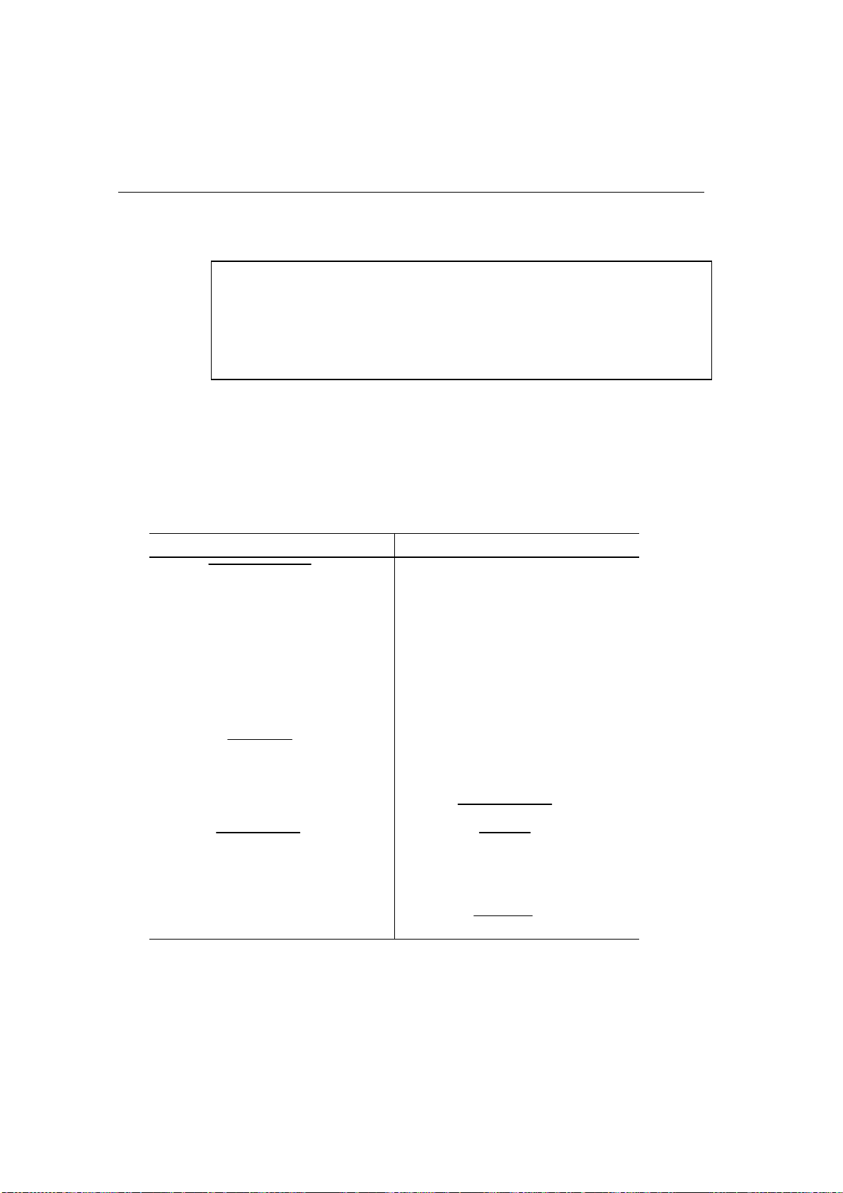
Parallel Interface Specifications
✒ Note
• To ensure best quality performance use an IEEE 1284 compliant parallel cable
between the printer and your computer. Only IEEE 1284 cables support all of
the advanced printing capabilities, like bi-directional communication. These
cables will be clearly marked with “IEEE-1284”.
• We recommend to use a parallel cable that is 2.0 meters (6.6 feet) or less.
Interface Connector Printer Side: Amphenol 57RE-40360-730B (D12)
or equivalent
A shielded cable should be used.
Pin Assignment
Pin No. Signal Direction Pin No. Signal Direction
1
DATA STROBE
Input 19 0V (S.G.) –
2 DATA 1 Input 20 0V (S.G.) –
3 DATA 2 Input 21 0V (S.G.) –
4 DATA 3 Input 22 0V (S.G.) –
5 DATA 4 Input 23 0V (S.G.) –
6 DATA 5 Input 24 0V (S.G.) –
7 DATA 6 Input 25 0V (S.G.) –
8 DATA 7 Input 26 0V (S.G.) –
9 DATA 8 Input 27 0V (S.G.) –
10
ACKNLG
Output 28 0V (S.G.) –
11 BUSY Output 29 0V (S.G.) –
12 PE Output 30 0V (S.G.) –
13 SLCT Output 31
INPUT PRIME
Input
14
AUTO FEED
Input 32
FAULT
Output
15 N.C. – 33 N.C. –
16 0V (S.G.) – 34 N.C. –
17 0V (S.G.) – 35 N.C. –
18 +5V – 36
SLCT IN
Input
Loading ...
Loading ...
Loading ...