Loading ...
Loading ...
Loading ...
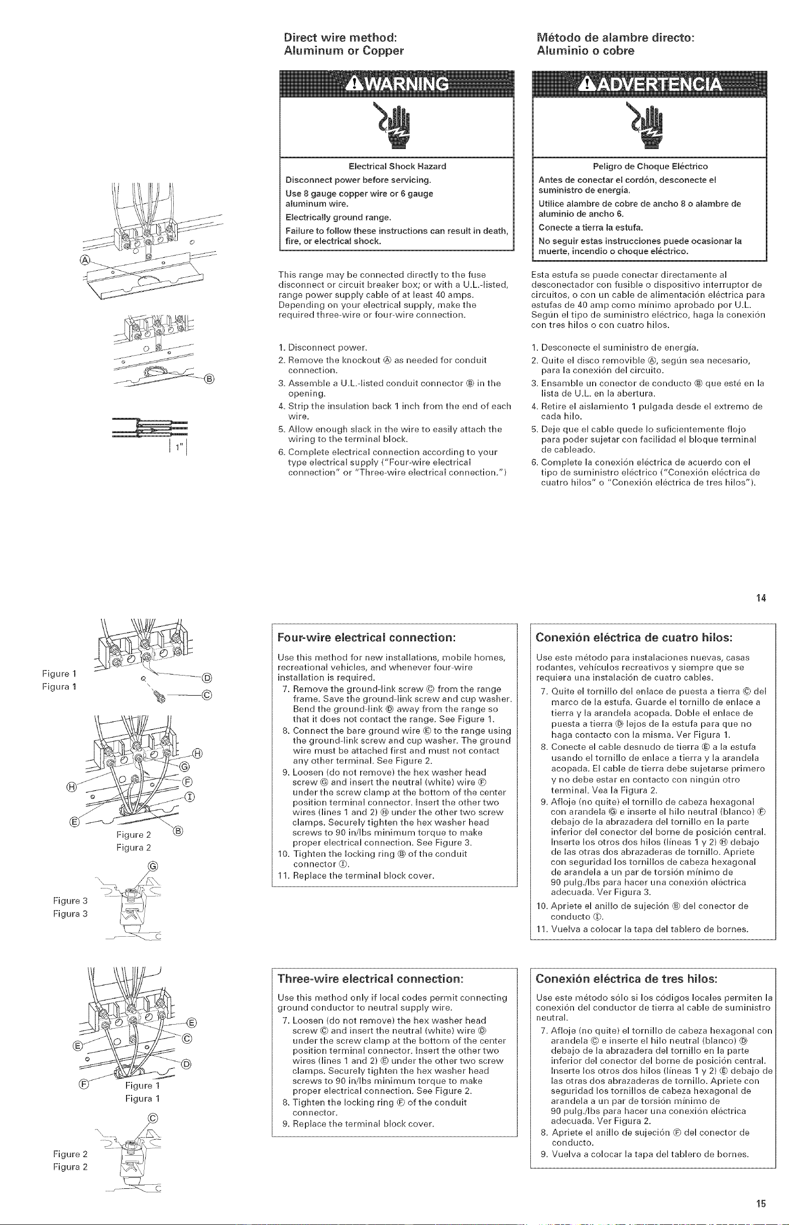
Direct wire method:
AUuminum or Copper
M6todo de aiambre directo:
AUuminie o cobre
I1" I
Electrical Shock Hazard
Disconnect power before servicing.
Use 8 gauge copper wire or 6 gauge
aluminum wire.
Electrically ground range.
Failure to follow these instructions can result in death,
fire, or emectrical shock.
This range may be connected directly to the fuse
disconnect or circuit breaker box; or with a U.L.-listed,
range power supply cane of at least 40 amps.
Depending on your ebctrbal supply, make the
required three-wire or four-wire connection.
1, Disconnect power.
2. Remove the knockout @ as needed for conduit
connection.
3. Assemble a U.hdisted conduit connector ® in the
opening,
4. Strip the insulation back 1 inch from the end of each
wi re.
5. Allow enough slack in the wire to easily attach the
wiring to the terminal block.
6. Complete electrical connection according to your
type electrical supply ("Four-wire electrical
connection" or "Three-wire electrical connection.")
Peligro de Cheque Em&ctrico
Antes de conectar el cord6n, desconecte et
suministro de energ[a.
Utimicealambre de cobre de ancho 8 o alambre de
aluminio de ancho &
Conecte a tierra ta estufa.
No seguir estas instrucciones puede ocasionar la
muerte, incendio o cheque el_ctrico.
Esta estufa se puede conectar directamente al
desconectador con fusible o dispositivo interrupter de
circuitos, o con un cable de dimentaci6n el6ctrica para
estufas de 40 amp come m_nimo aprobado per U.L.
Segun el tipo de suministro el6ctrico, haga la conexi6n
con tres hilos o con cuatro hilos.
1. Desconecte el suministro de energ_a,
2. Quite el disco removibb @, segun sea necesario,
para la conexi6n del circuito,
3. Ensamble un conector de conducto ® que este en la
lista de U.L en la abertura.
4. Retire el aislamiento 1 pulgada desde el extreme de
cada hilo.
5. Deje que el cable quede Io suficientemente flojo
para poder sujetar con facilidad el bloque terminal
de cabbado.
6. Complete la conexi6n el6ctrica de acuerdo con el
tipo de suministro electrico ("Conexi6n el6ctrica de
cuatro hilos" o "Conexi6n el6ctrica de tres hilos").
Figure 1
Figura 1
Figure 3
Figura 3
Figure 2 \"(_
Figura 2
c
Four-wire electrical connection:
Use this method for new installations, mobile homes,
recreational vehicles, and whenever four-wire
installation is required,
7. Remove the ground-link screw © from the range
frame. Save the ground-link screw and cup washer.
Bend the ground-link @ away from the range so
that it does not contact the range. See Figure 1.
8. Connect the bare ground wire _to the range using
the ground-link screw and cup washer. The ground
wire must be attached first and must not contact
any other terminal. See Figure 2.
9. Loosen (do not remove) the hex washer head
screw @ and insert the neutral (white) wire
under the screw clamp at the bottom of the center
position terminal connector. Insert the other two
wires (lines 1 and 2) @ under the other two screw
clamps, Securely tighten the hex washer head
screws to 90 in/Ibs minimum torque to make
proper electrical connection. See Figure 3.
10. Tighten the locking ring ® of the conduit
connector _.
11, Replace the terminal block cover.
14
Conexi6n el6etrica de cuatro hilos:
Use este metodo para instalaciones nuevas, casas
rodantes, veh_culos recreativos y siempre que se
requiera una instalaci6n de cuatro cables.
7. Quite el tornillo del enlace de puesta a tierra © del
marco de la estuf& Guarde el tornillo de enlace a
tierra y la arandela acopada. DoNe el enlace de
puesta a tierra @ lejos de la estufa para que no
haga contacto con la misma. Ver Figura 1,
8. Conecte el cable desnudo de tierra @ a la estufa
usando el tornillo de enlace a tierra y la arandela
acopada. El cane de tierra debe sujetarse primero
y no debe estar en contacto con ninguJn otro
terminal. Vea la Figura 2.
9. Afloje (no quite) el tornillo de cabeza hexagonal
con arandela @ e inserte el hiio neutral (blanco)
debajo de la abrazadera del tornillo en la parte
inferior del conector del borne de posici6n central
Inserte los otros dos hiios (Hneas 1 y 2) (_ debajo
de las otras dos abrazaderas de tornillo. Apriete
con seguridad los torniiios de cabeza hexagonal
de arandela a un par de torsion m_nimo de
96 pulg./Ibs para hacer una conexion electrica
adecuada. Ver Figura 3.
10. Apriete el anillo de sujeci6n @ del conector de
conducto (_,
11. Vuelva a colocar la tapa del tablero de berries.
o ©
Figure 1
Figura 1
_}b _,
Figure 2
Figura 2
Three-wire electrical connection:
Use this method only if local codes permit connecting
ground conductor to neutral supply wire.
7. Loosen (do not remove) the hex washer head
screw @ and insert the neutral (white) wire @
under the screw damp at the bottom of the center
position terminal connector, insert the other two
wires (lines 1 and 2} @ under the other two screw
clamps, Securely tighten the hex washer head
screws to 90 in/Ibs minimum torque to make
proper electrical connection. See Figure 2.
8. Tighten the locking ring (_ of the conduit
connector.
9, Replace the terminal block cover.
Conexi6n elbetrica de tres hilos:
Use este metodo solo si los codigos locales permiten la
conexion del conductor de tierra al cane de suministro
neutral
7. Afloje (no quite) el tornillo de cabeza hexagonal con
arandela © e inserte el hiio neutral (blanco) @
debajo de la abrazadera del tornillo en la parte
inferior del conector del borne de posici6n central,
Inserte los otros dos hiios (Hneas 1 y 2) @ debajo de
las otras dos abrazaderas de tornillo. Apriete con
seguridad los torniiios de cabeza hexagonal de
arandela a un par de torsi6n m_nimo de
96 pulg./Ibs para hacer una conexion electrica
adecuada. Ver Figura 2.
8. Apriete el anillo de sujeci6n @ del conector de
conducto.
9. Vuelva a colocar la tapa del tablero de bornes.
15
Loading ...
Loading ...
Loading ...