Loading ...
Loading ...
Loading ...
Power supply cord method: Mbtodo del cord6n de alimentaci6n
elbctrica:
Electrical Shock Hazard
Disconnect power before servicing.
Use a new 40 amp power supply cord.
Plug into a grounded outmet.
Failure to follow these instructions can result in death,
fire, or electrical shock.
WARNING -improper connection of the equipment-
grounding conductor can result in a risk of electric
shock. Check with a qualified electrician or service
personnel if you are in doubt as to whether the range
is properly grounded. Do not modify the power supply
cord plug, if it will not fit the outlet, have a proper
outlet installed by a qualified electrician.
This range is manufactured with the neutral terminal
connected to the cabinet. Use a three-wire, U.L=listed,
at bast 40 amp power supply cord (pigtail}; or if local
codes do not permit ground through the neutral, use a
four-wire power supply cord rated at 250 volts, at least
40 amp and investigated for use with ranges. (See
"Four-wire electrical connection/')
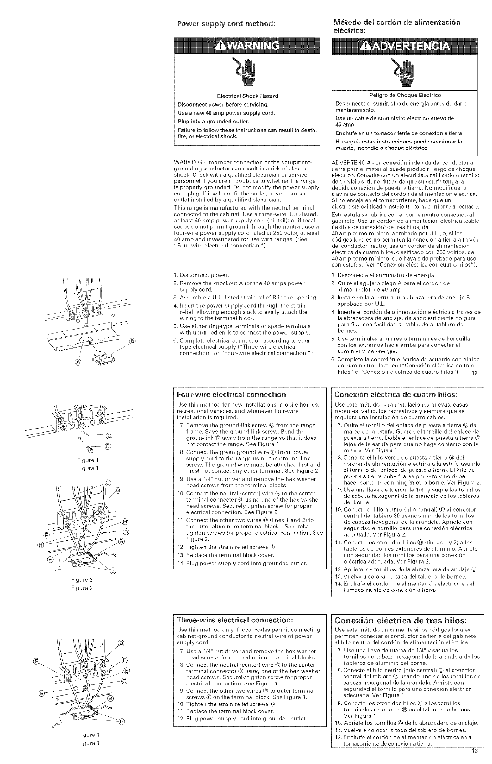
1. Disconnect power.
2. Remove the knockout A for the 40 amps power
supply cord.
3. Assemble a U.L=listed strain relief B in the opening.
4. insert the power supply cord through the strain
relief, allowing enough slack to easily attach the
wiring to the terminal block.
B. Use either ring-type terminals or spade terminals
with upturned ends to connect the power supply.
6. Complete electrical connection according to your
type electrical supply ("Three-wire electrical
connection" or "Four-wire electrical connection/')
Peligro de Choque Et_ctrico
Desconecte el suministro de energia antes de dade
mantenimiento.
Use un cable de suministro el_ctrico nuevo de
40 amp.
Enchufe en un tomacorriente de conexi6n a tierra.
No seguir estas instrucciones puede ocasionar la
muerte, incendio o choque el_ctrico.
ADVERTENCIA - La conexion indebida del conductor a
tierra para el material puede producir riesgo de choque
electrico, Consulte con un electricista calificado o tecnico
de servicio sitiene dudas de que su estufa tenga ia
debida conexi6n de puesta a tierra. No modifique la
clavija de contacto del cord6n de alimentacion el6ctrica.
Si no encaja en el tomacorriente, haga que un
electricista calificado instale un tomacorriente adecuado.
Esta estufa se fabrica con el borne neutro conectado al
gabinete. Use un cordon de alimentacion electrica (caNe
flexible de conexi6n} de tres hilos, de
40 amp como mu'nimo, aprobado pot U_L, o, si los
c6digos locales no permiten la conexi6n a tierra a traves
del conductor neutro, use un cord6n de alimentaci6n
electrica de cuatro hilos, clasificado con 250 voltios, de
40 amp como mu'nimo, que haya sido probado para uso
con estufas, (Vet "Conexi6n eiectrica con cuatro hiios"}.
1, Desconecte el suministro de energu'a.
2. Quite el agujero ciego A para el cord6n de
alimentaci6n de 40 amp.
3. Instale en la abertura una abrazadera de anclaje B
aprobada pot U,L
4. Inserte el cord6n de alimentaci6n electrica a traves de
la abrazadera de anclaje, dejando suficiente holgura
para fijar con facilidad el cableado al tablero de
bornes.
B. Use terminales anulares o terminales de horquilla
con los extremos hacia arriba para conectar el
suministro de energ_a,
6. Complete la conexi6n electrica de acuerdo con el tipo
de suministro electrico ("Conexion electrica de tres
hilos" o "Conexion electrica de cuatro hilos"}. 12
\
%---©
Figure 1
Figura 1
Figure 2
Figura 2
Fourowire electrical connection:
Use this method for new installations, mobile homes,
recreational vehicles, and whenever four-wire
installation is required.
7. Remove the ground-link screw @ from the range
frame_ Save the grounddink screw. Bend the
groun-link @ away from the range so that it does
not contact the range. See Figure 1.
8. Connect the green ground wire @ from power
supply cord to the range using the ground-link
screw. The ground wire must be attached first and
must not contact any other terminal See Figure 2.
9. Use a 1/4" nut driver and remove the hex washer
head screws from the terminal blocks.
10. Connect the neutral (center) wire (_ to the center
terminal connector @ using one of the hex washer
head screws. Securely tighten screw for proper
electrical connection. See Figure 2.
11. Connect the other two wires @ (lines 1 and 2} to
the outer aluminum terminal blocks. Securely
tighten screws for proper electrical connection. See
Figure 2.
12. Tighten the strain relief screws _.
13. Replace the terminal block cover.
14. Plug power supply cord into grounded outlet.
Cone×i6n electrica de cuatro hilos:
Use este metodo para instalaciones nuevas, casas
rodantes, veh_culos recreativos y siempre que se
requiera una instalacion de cuatro cables.
7. Quite el tornillo del enlace de puesta a tierra © del
marco de la estufa. Guarde el tornillo del enlace de
puesta a tierra. DoNe el enlace de puesta a tierra @
lejos de la estufa para que no haga contacto con la
misma. Vet Figura 1.
8. Conecte el hilo verde de puesta a tierra @ del
cord6n de alimentacion electrica a la estufa usando
eltornillodelenlace depuestaatierra. EIhilode
puesta a tierra debe fijarse primero y no debe
hacer contacto con ningun otto borne. Vet Figura 2.
9. Use una iiave de tuerca de 1/4" y saque los torniiios
de cabeza hexagonal de la arandela de los tableros
del borne.
10. Conecte el hiio neutro (hiio central} (_ al conector
central del tablero _) usando uno de los tornillos
de cabeza hexagonal de la arandela. Apriete con
seguridad el tornillo para una conexion electrica
adecuada. Ver Figura 2,
11. Conecte los otros dos hiios @ (l_neas 1 y 2) a los
tableros de bornes exteriores de aluminio. Apriete
con seguridad los tornillos para una conexi6n
electrica adecuada. Vet Figura 2.
12. Apriete los tornillos de la abrazadera de anclaje _.
13, Vuelva a colocar la tapa del tablero de bornes,
14. Enchufe el cordon de alimentacion electrica en el
tomacorriente de conexion a tierra,
@
Figure 1
Figura 1
Three-wire electrical connection:
Use this method only if local codes permit connecting
cabinet-ground conductor to neutral wire of power
supply cord.
7. Use a 1/4" nut driver and remove the hex washer
head screws from the aluminum terminal blocks.
8. Connect the neutral (center) wire ©to the center
terminal connector @ using one of the hex washer
head screws. Securely tighten screw for proper
electrical connection. See Figure 1.
9. Connect the other two wires _) to outer terminal
screws _ on the terminal block. See Figure 1.
10. Tighten the strain relief screws @_
11. Replace the terminal block cover.
12. Plug power supply cord into grounded outlet.
Cone×i6n eJecttica de tres hHos:
Use este metodo unicamente si los codigos locales
permiten conectar el conductor de tierra del gabinete
al hilo neutro del cordon de alimentacion electrica.
7. Use una llave de tuerca de 1/4" y saque los
tornillos de cabeza hexagonal de la arandela de los
tableros de aluminio del borne.
8. Conecte el hilo neutro (hilo central} @ al conector
central del tablero @ usando uno de los tornillos de
cabeza hexagonal de la arandela. Apriete con
seguridad el tornillo para una conexi6n electrica
adecuada. Vet Figura 1_
9. Conecte los otros dos hilos @ a Iostornillos
terminales exteriores (_ en el tablero de bornes.
Vet Figura 1_
10. Apriete los tornillos @ de la abrazadera de anclaje.
11.Vuelva a colocar la tapa del tablero de bornes.
12. Enchufe el cord6n de alimentacion electrica en el
tomacorriente de conexion a tierra.
13
Loading ...
Loading ...
Loading ...