Loading ...
Loading ...
Loading ...
BDS 280/580
6
BDS Rear Panel Controls and Connections
Press this capacitive button to turn the BDS system ON. If the system is already ON, press
this button to push the system to Standby, Sleep or OFF mode.
The following table describes the different modes along with the LED display.
Mode Operation LED display
ON Press the power button White
Standby Long press on the power
button
Amber
OFF Press the power button
when in operational
mode
OFF
Sleep • No activity for 15 min
• Short press on the
power button on the
front panel.
• Short press on the
remote control
power button or
power off command
from external IR or
remote app
Amber
NOTE: While the system is powering on the volume ring will spin till the boot
process is complete.
5. NFC for Bluetooth pairing: Near Field Communication (NFC) is used for fast
Bluetooth pairing of compatible Android
TM
and Windows® mobile devices. Place the
mobile device near the NFC logo on the top front of the system to pair or unpair.
NOTE: The system can be brought to Operational mode by tapping on the
NFC area.
6. Eject button (appears only when a disc has been inserted): Touch this button
to eject a disc from the BDS system’s built-in disc slot. Before touching this button, make
sure no objects block the disc-slot.
NOTE: If you do not remove the ejected disc within 90 seconds, it will auto-
matically re-load into the disc slot for protection.
7. Information display: Various messages appear on this display in response to
commands and to show the audio/video that is playing, the BDS system’s settings or
other aspects of the BDS system’s status as described throughout this manual.
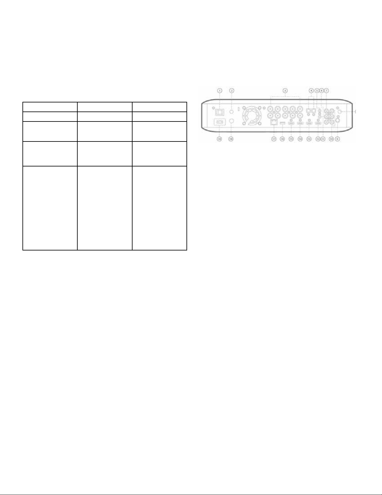
BDS Rear Panel Controls and Connections
1. Main Power Switch
2. Antenna Air
3. Speaker outputs
4. Optical Digital Audio (S/PDIF) inputs
5. Trigger Output
6. AUX 1 input and AUX 2 input
7. Subwoofer output
8. Antenna Wi-Fi
9. FM radio antenna output
10. Coaxial digital audio (S/PDIF) input
11. IR Remote input
12. HDMI output (ARC)
13. HDMI 1/MHL input
14. HDMI 2 input
15. HDMI 3 (Apple) input
16. USB input
17. Network Connector
18. WPS button
19. AC Power input
1. Main Power switch: This mechanical switch turns the BDS system’s power supply
ON or OFF. After you have made and verified all connections, set this switch to the ON
position. During normal use, you will usually leave this switch set to ON; it cannot be
turned ON or OFF using the remote control. To conserve energy when you are not using
the system for an extended period of time, set this switch to OFF.
2. Antenna Air: Connect the antenna accessory labeled Air here for improved Wi-Fi
reception.
3. Speaker Outputs: Use the speaker wires supplied with the speakers to connect the
speakers to the proper terminals.
• The BDS system has connections for left and right speakers.
4. Optical Digital (S/PDIF) Inputs: Connect the optical digital output of an audio
source component here. The signal may be a Dolby Digital, DTS® or standard PCM digital
audio.
5. Trigger Output: This connector provides 12V DC whenever the system is ON. It can
be used to turn on and off other devices such as a powered subwoofer.
6. AUX 1 and AUX 2 Input: Use these connectors to connect to an audio source device
(such as a tape deck). Do not connect a turntable to these connectors without a phono
preamp.
Loading ...
Loading ...
Loading ...