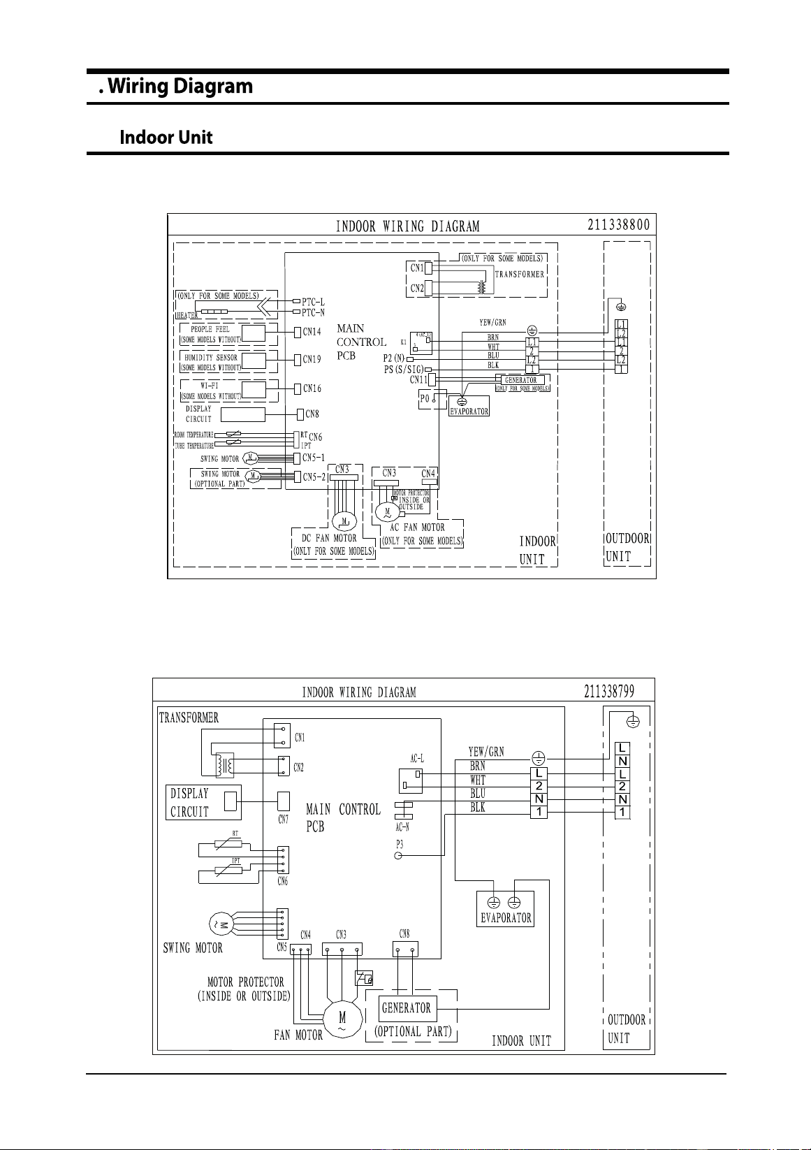
Installation Diagram of Indoor Unit and
Outdoor Unit
$5-6$/%:.1&99
$5-6$/%:.1&99
$5-6)/%:.1&99
$5-6)/%:.1&99
$5-6)/%:.1&99
$5-6)/%:.1&99
$5-6$/%:.;&99
$5-6$/%:.;&99
$5-6)/%:.;&99
$5-6)/%:.;&99
$5-6)/%:.;&99
$5-6)/%:.;&99
/12K 18K 24K
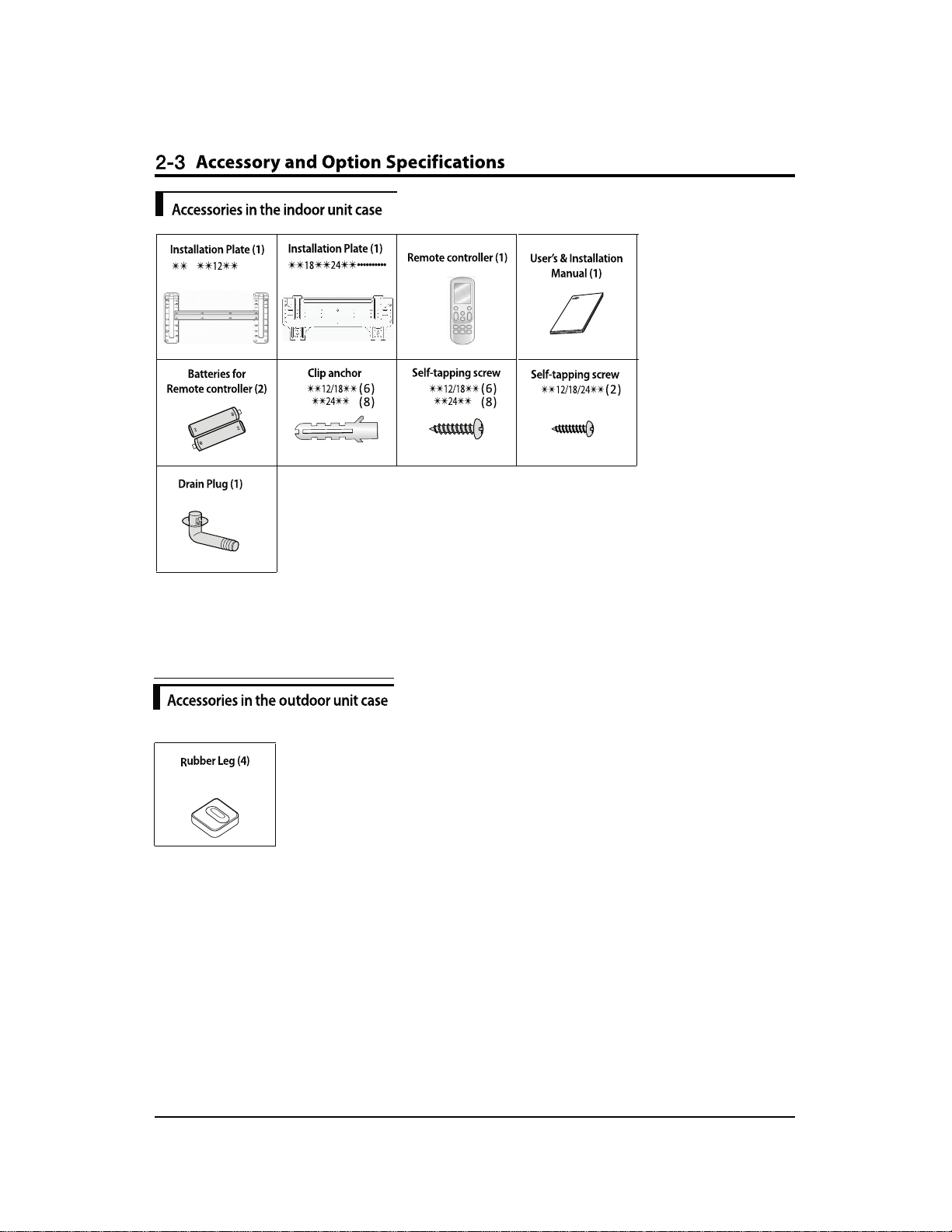
2-3 Accessory and Option Specifications .................................................................................... 2-ϴ
3-1 Checking before use............................................................................................................... 3-1
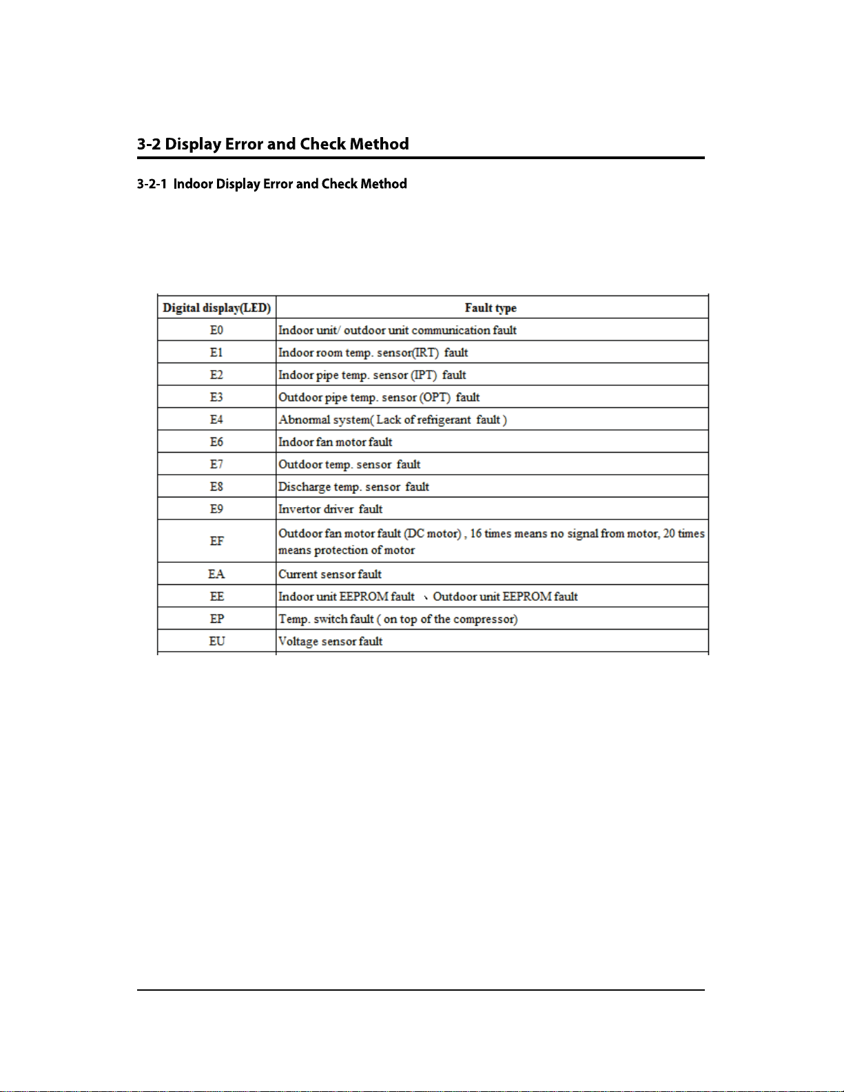
3-2 Display Error and Check Method ......................................................................................... 3-2
3-3 Checking the remote controller ........................................................................................... 3-3
5
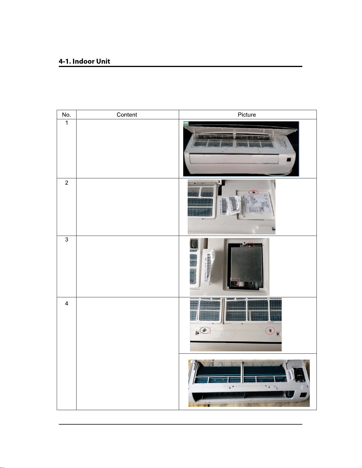
4-1 Indoor Unit.............................................................................................................................. 4-1
4-2 Outdoor Unit........................................................................................................................... 4-ϭϳ
5-1
5-1 Indoor Unit.............................................................................................................................. 5-1
5-2 Outdoor Unit........................................................................................................................... 5-2
6
6-1
6-1 Indoor Main PCB-ϵ<12<........................................................................................................ 6-1
6-2 Indoor Main PCB-ϭϴ<......................................................................................................... 6-ϯ
ϲͲϯ/ŶĚŽŽƌDĂŝŶWͲϮϰ<.................................................................................................................... .. ϲͲϱ
6-3 Indoor display PBA-ϵ<ϭϮ<K..................................................................................................... 6-ϳ
6-4 Indoor display PBA-ϭϴ<ϮϰK......................................................................................................6-ϴ
4-1
3-1
2-1
1-1
1-1
1-1
1-1
1-2
1-2
2-1
2-2
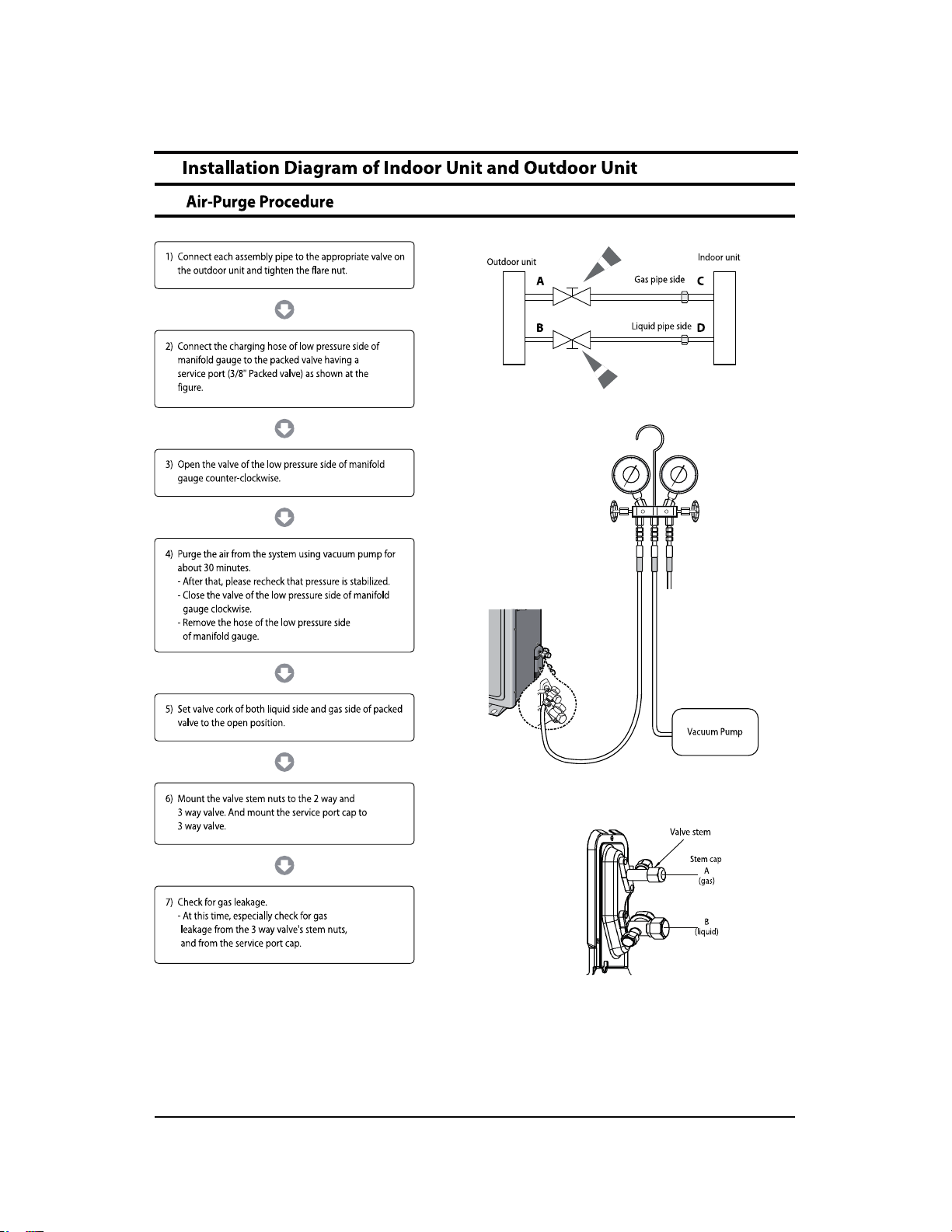
9-1 Air-Purge Procedure ........................................................................................................... 9-1
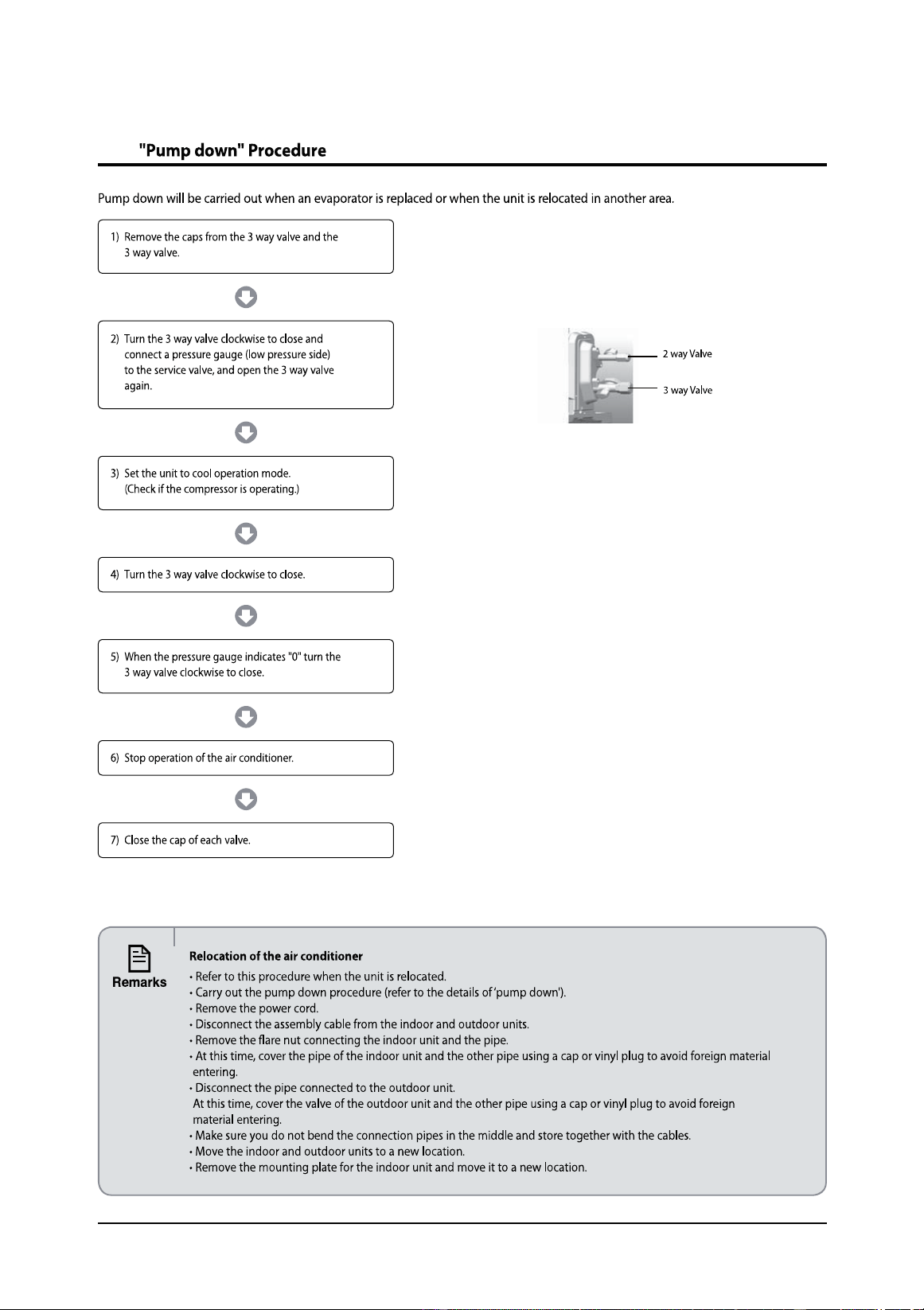
9-2 Pump down Procedure ................................................................................................ 9-2
7-1 Indoor Main PCB .................................................................................................................... 7-1
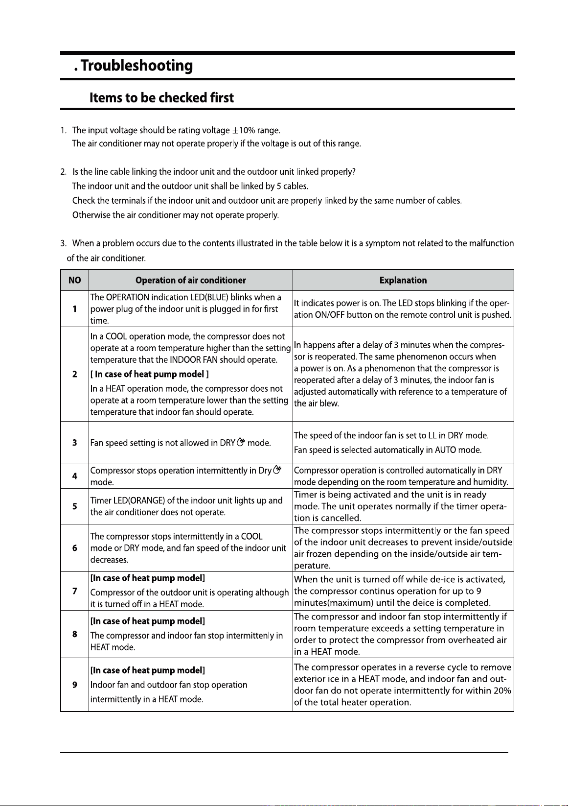
8-1 Items to be checked first ...................................................................................................... 8-1
8-2 dƌŽƵďůĞƐŚŽŽƚŝŶŐƉƌŽĐĞĚƵƌĞ ................................................................................................. 8-2
8-3 W/ŶƐƉĞĐƚŝŽŶDĞƚŚŽĚ....................................................................................................... 8-ϭϮ
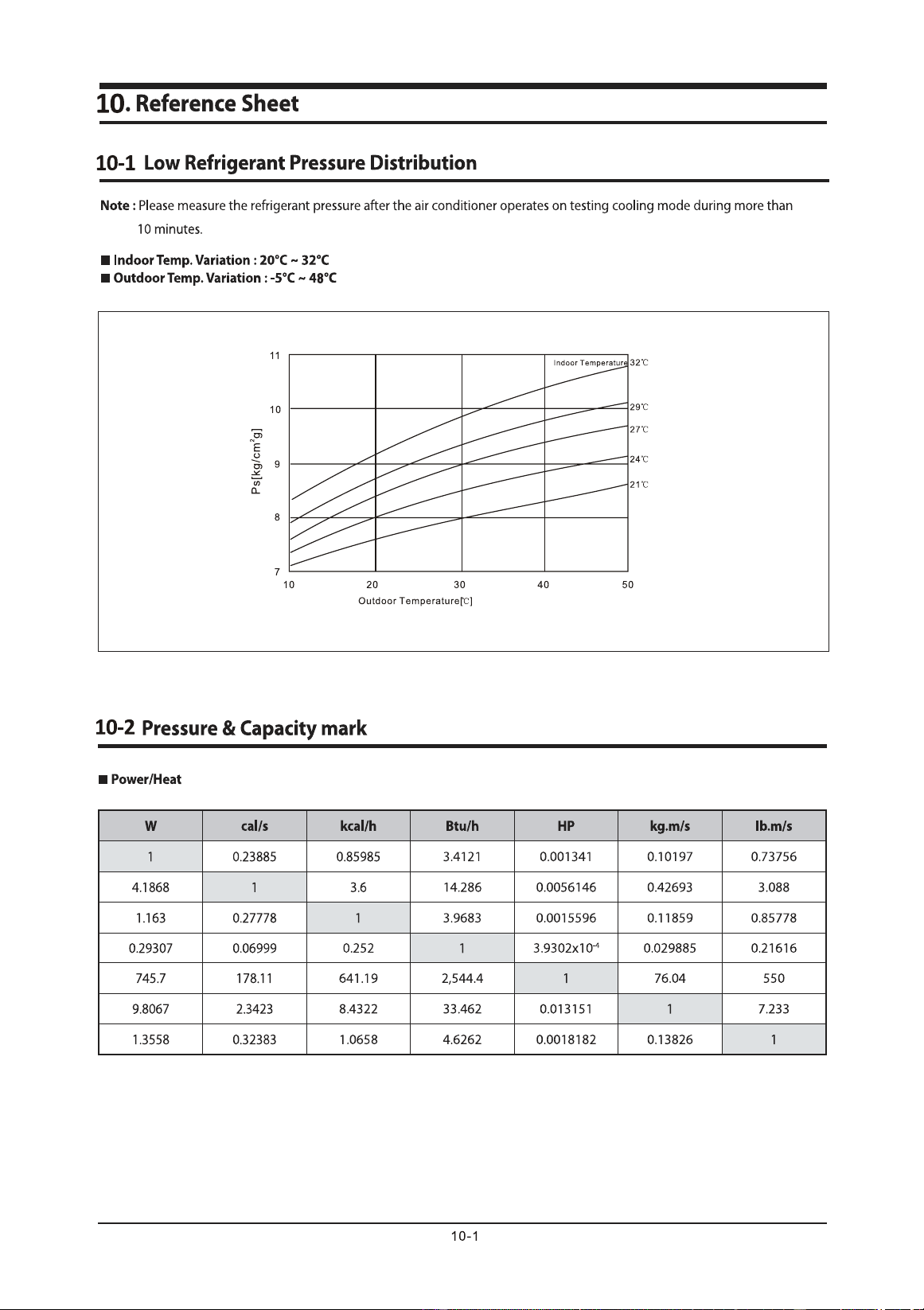
10-1
10-2
10-3
10-4
10-5
10-6
10-7 Reference Sheet .................................................................................................................. 10-ϴ
10-1
10-ϭ
10-Ϯ
10-ϱ
10-ϲ
10-ϳ
7
7-1
8
8-1
9
9-1
10
10-1
1-1
1-2
2-1
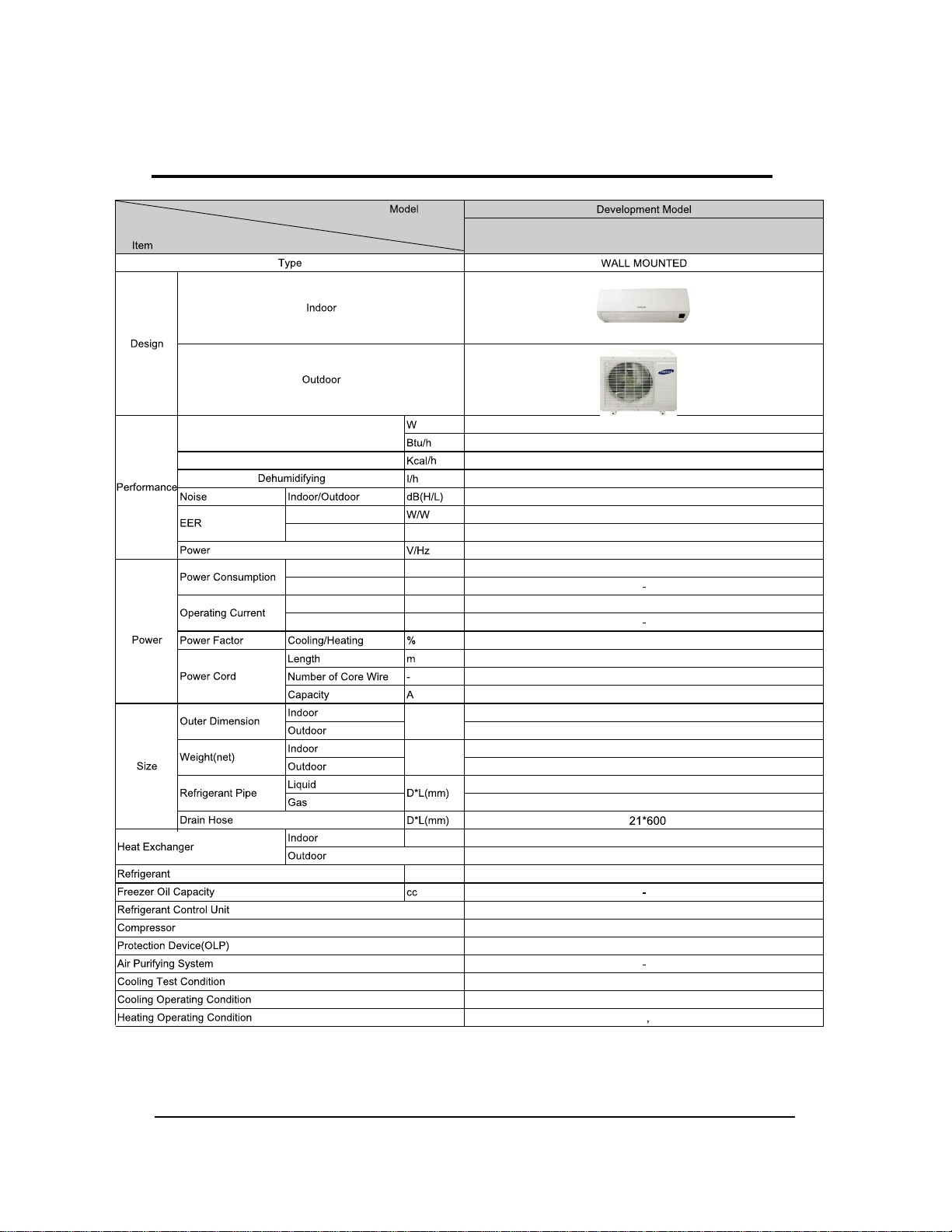
2-2 Product Specifications
2-2
$5-6$/%:.1&99
,R$
/
/
5./6
îî
6
$61'8(=
V+]
.
1
/
/
9%
Ļ/Ļ
/
îî
ĭîîîLQRXW
ĭîîîLQRXW
internal
EEEV
Φ
Cooling /Heating
Cooling /Heating
Cooling /Heating
Cooling /Heating Btu/Wh
Cooling /Heating Btu/Wh
Cooling /Heating W
Cooling /Heating A
Cooling /Heating
W*H*D
(inch)
lbs
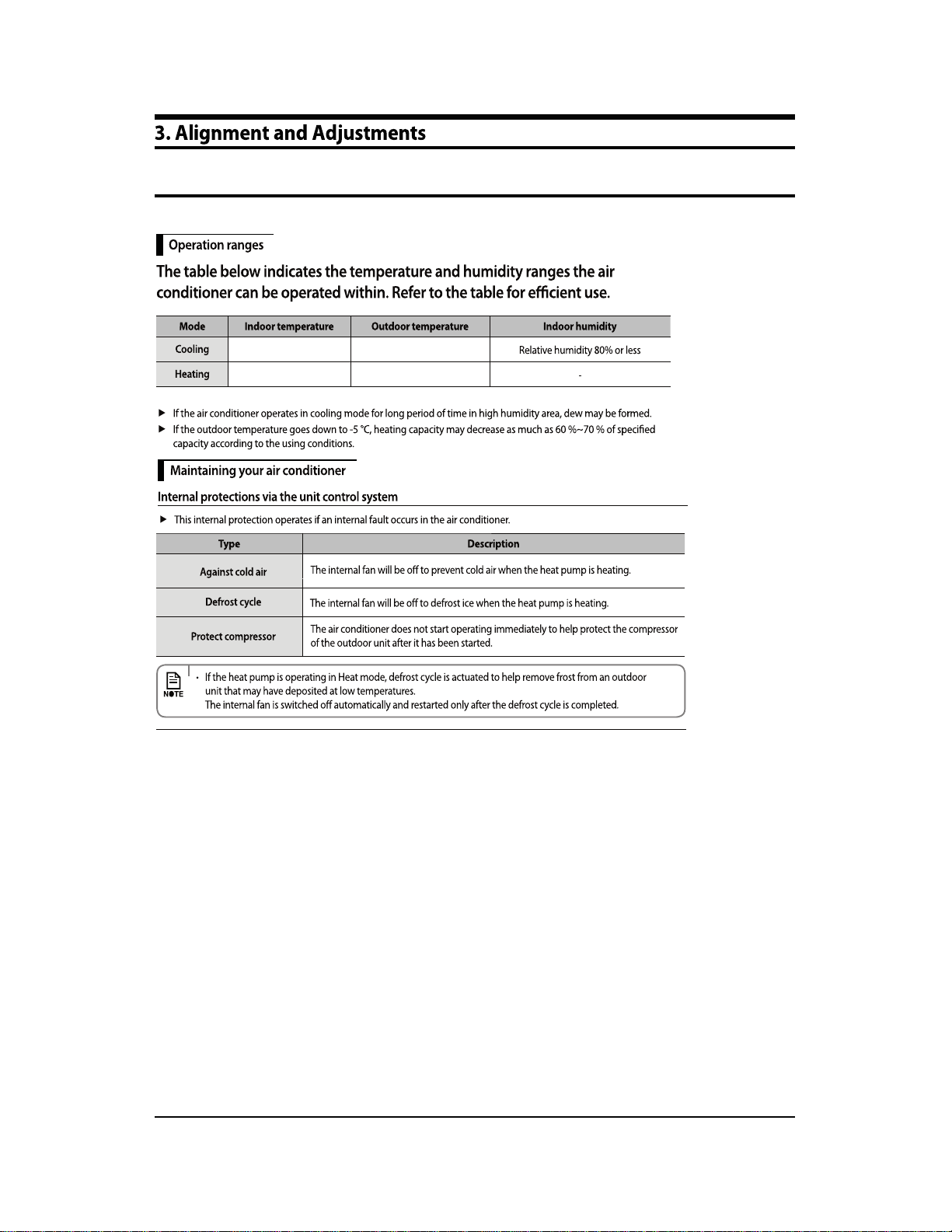
INDOOR UNIT:DB80.6 ℉/WB66.2℉,OUTDOOR UNIT:DB95//WB75.2℉
INDOOR UNIT:62.6℉~89.6℉,OUTDOOR UNIT:14℉~114.8℉
INDOOR UNIT:19.4℉~80.6℉,OUTDOOR UNIT:5℉~75.2℉
lbs
mm
mm
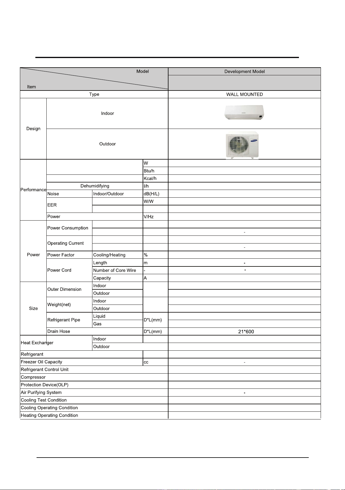
2-2 Product Specifications
2-3
$5-6$/%:.1&99
,R$
/
/
./
îî
6
$6'8.7$-7
V+]
.
1
/
/
%
Ļ/Ļ
/
îî
ĭîîîLQRXW
ĭîîîLQRXW
internal
ΦΦ
EEV
Cooling /Heating
Cooling /Heating
Cooling /Heating
Cooling /Heating Btu/Wh
Cooling /Heating
W
Cooling /Heating Btu/Wh
Cooling /Heating A
Cooling /Heating
A
W*H*D
(inch)
lbs
INDOOR UNIT:DB80.6 ℉/WB66.2℉,OUTDOOR UNIT:DB95//WB75.2℉
INDOOR UNIT:62.6℉~89.6℉,OUTDOOR UNIT:14℉~114.8℉
INDOOR UNIT:19.4℉~80.6℉,OUTDOOR UNIT:5℉~75.2℉
lbs
mm
mm

2-2 Product Specifications
2-4
$5-6)/%:.1&99
,R$
/
/
/
îî
6
$61'8(=
V+]
.
.
1
/
/
%
Ļ/Ļ
/
îî
ĭîîîLQRXW
ĭîîîLQRXW
internal
ΦΦ
EEV
Cooling /Heating A
Cooling /Heating A
Cooling /Heating W
Cooli
ng /Heating Btu/Wh
Cooling /Heating Btu/Wh
Cooling /Heating
Co
oling /Heating
Cooling /Heating
W*H*D
(inch)
lbs
INDOOR UNIT:DB80.6 ℉/WB66.2℉,OUTDOOR UNIT:DB95//WB75.2℉
INDOOR UNIT:62.6℉~89.6℉,OUTDOOR UNIT:14℉~114.8℉
INDOOR UNIT:19.4℉~80.6℉,OUTDOOR UNIT:5℉~75.2℉
lbs
mm
mm

2-2 Product Specifications
2-5
$5-6)/%:.1&99
,R$
/
/
/
îî
6
$6'8.7$-7
V+]
.
1
/
/
%
Ļ/Ļ
/
îî
ĭîîîLQRXW
ĭîîîLQRXW
internal
ΦΦ
EEV
Cooling /Heating
Cooling /Heating Btu/Wh
Cooling /Heating A
Cooling /Heating A
Cooling /Heating
Cooling /Heating
Cooling
/Heating
Cooling /Heating W
W*H*D
(inch)
lbs
INDOOR UNIT:DB80.6 ℉/WB66.2℉,OUTDOOR UNIT:DB95//WB75.2℉
INDOOR UNIT:62.6℉~89.6℉,OUTDOOR UNIT:14℉~114.8℉
INDOOR UNIT:19.4℉~80.6℉,OUTDOOR UNIT:5℉~75.2℉
lbs
mm
mm

2-2 Product Specifications
2-6
$5-6)/%:.1&99
,R$
/
/
/
îî
6
'$6&)=
V+]
1
/
/
%
Ļ/Ļ
/
îî
ĭîîîLQRXW
ĭîîîLQRXW
internal
ΦΦ
EEV
Cooling /Heating
Cooling /Heating
Cooling /Heating
Cooling /Heating
Btu/Wh
Cooling /Heating W
Cooling /Heating
Btu/Wh
Coo
ling /Heating A
Cooling /Heating A
W*H*D
(inch)
lbs
INDOOR UNIT:DB80.6 ℉/WB66.2℉,OUTDOOR UNIT:DB95//WB75.2℉
INDOOR UNIT:62.6℉~89.6℉,OUTDOOR UNIT:14℉~114.8℉
INDOOR UNIT:19.4℉~80.6℉,OUTDOOR UNIT:5℉~75.2℉
lbs
mm
mm

2-2 Product Specifications
2-7
$5-6)/%:.1&99
,R$
/
/
/
îî
'$6&07
V+]
1
/
/
%
Ļ/Ļ
/
îî
ĭîîîLQRXW
ĭîîîLQRXW
internal
ĭî
EEEV
Cooling /Heating A
Cooling /Heating A
Cooling /Heating
W
Cooling /Heating Btu/Wh
Cooling /Heating
Btu/Wh
Cooling /Heating
Cooling /Heating
Cooling /Heating
W*H*D
(inch)
lbs
INDOOR UNIT:DB80.6 ℉/WB66.2℉,OUTDOOR UNIT:DB95//WB75.2℉
INDOOR UNIT:62.6℉~89.6℉,OUTDOOR UNIT:14℉~114.8℉
INDOOR UNIT:19.4℉~80.6℉,OUTDOOR UNIT:5℉~75.2℉
lbs
mm
mm
2-8
9
DB82-02428A
DB82-02429A
DB82-02651A
3-1 Checking before use
3-1
62.6℉~89.6℉
14℉~114.8℉
9.4℉~80.6℉, 5℉~75.2℉
3-2
.
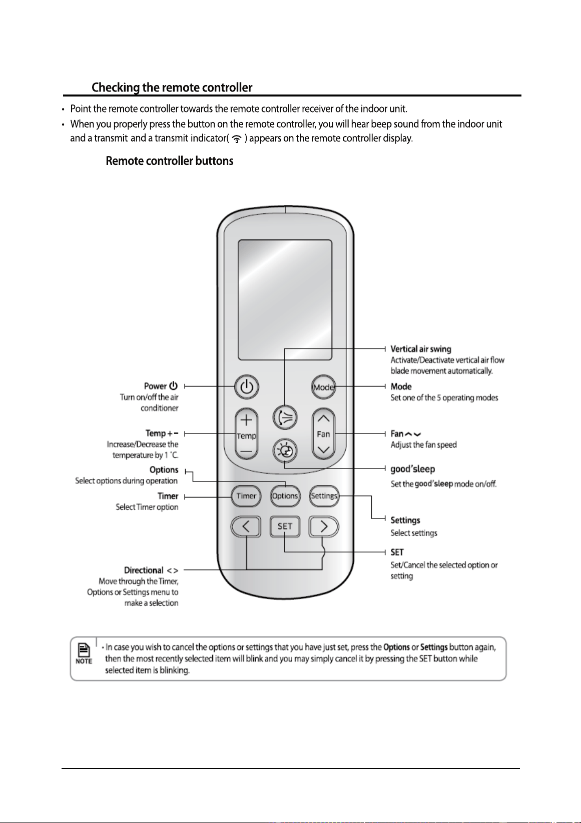
3-3
3-3-1
3-3
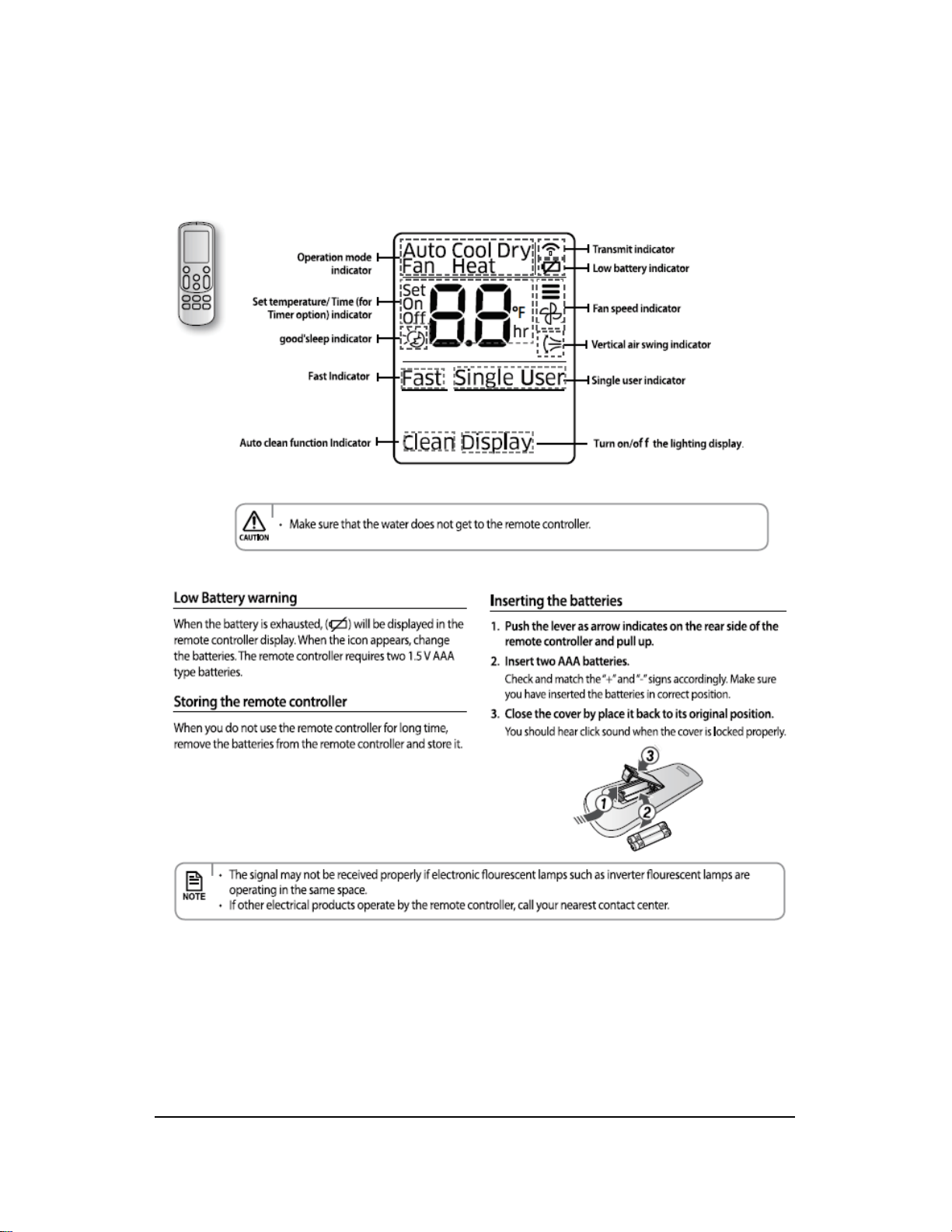
3-3-2 Remote controller display
3-4

4-1
4-2
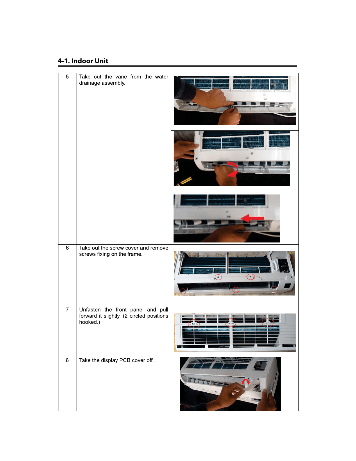
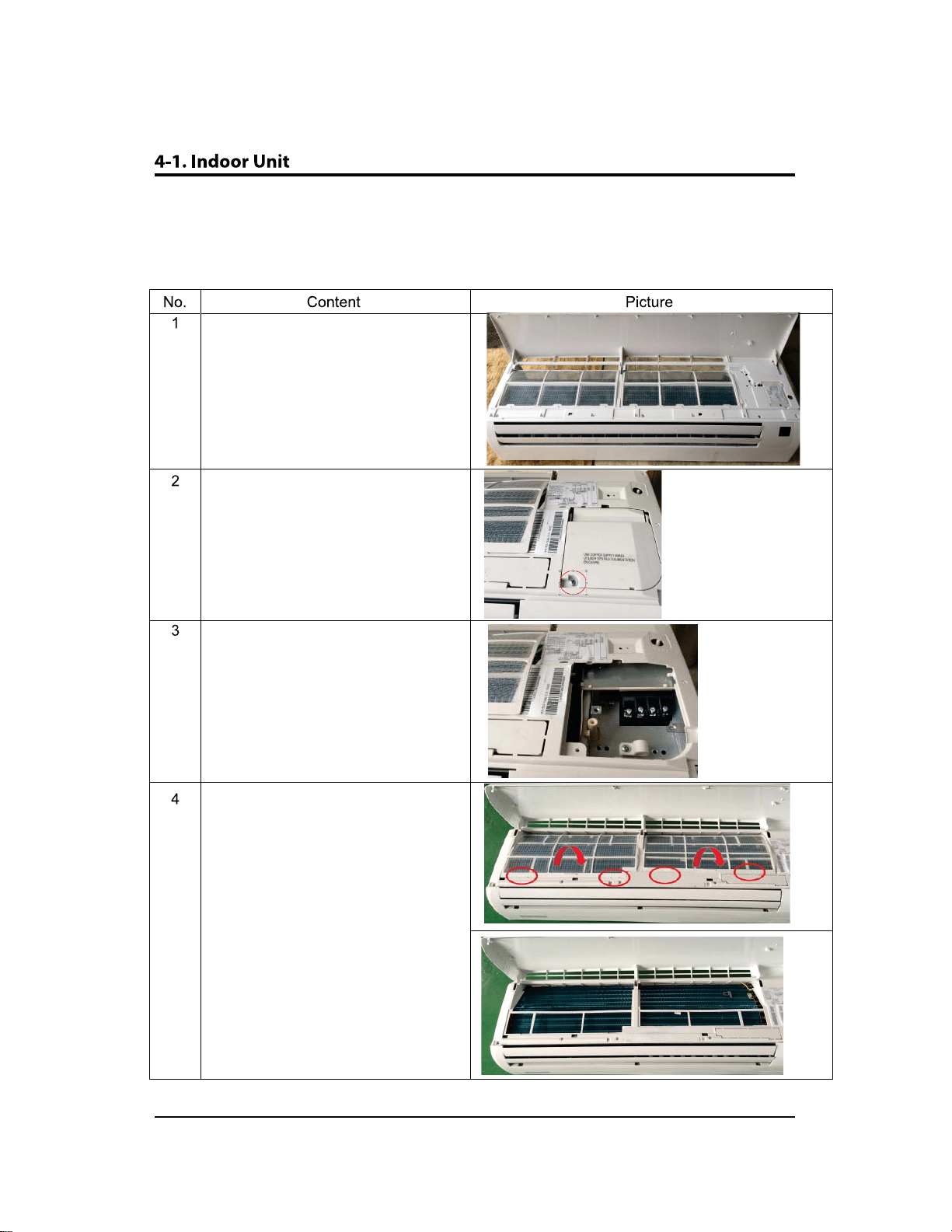
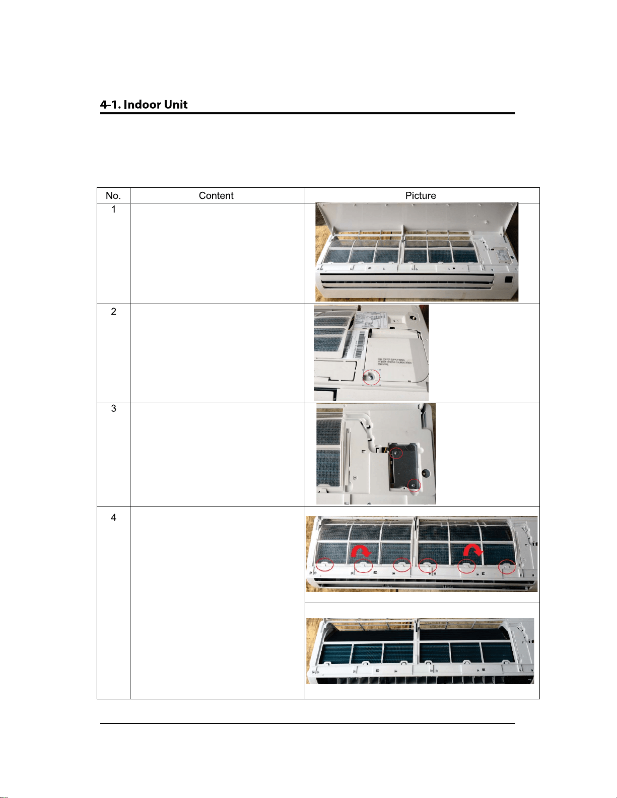
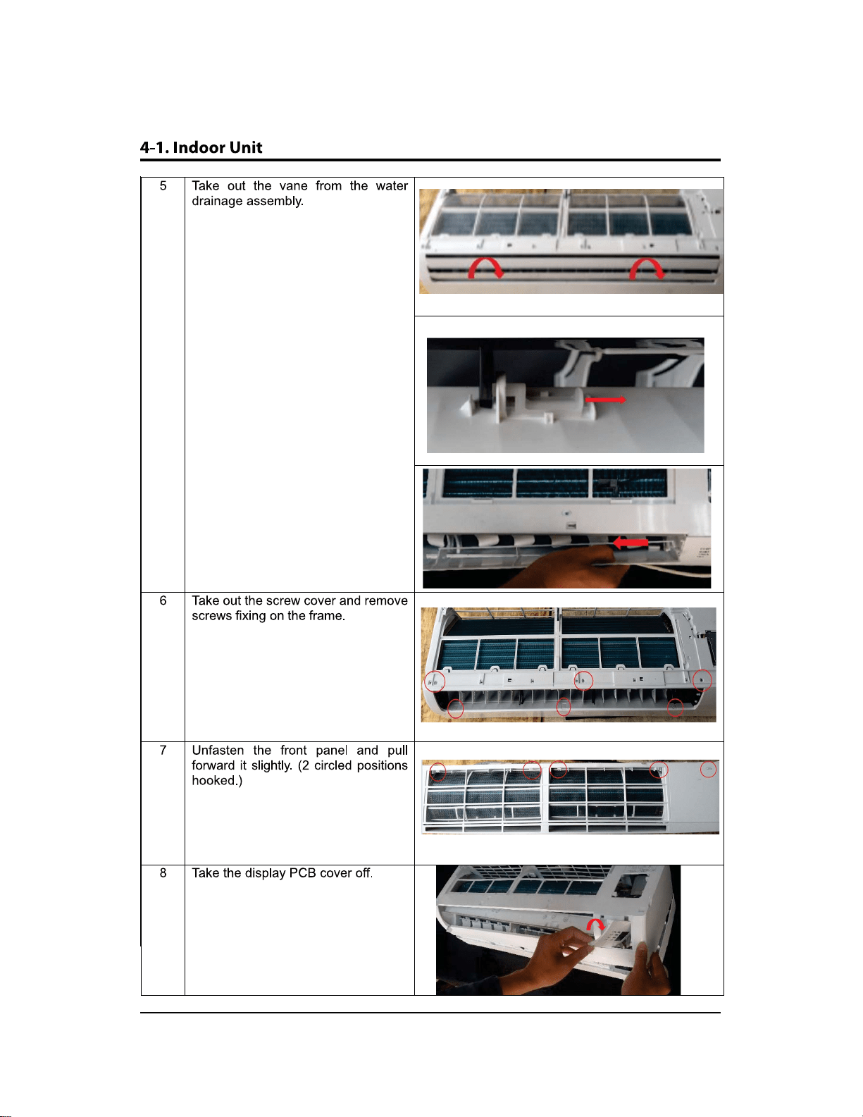
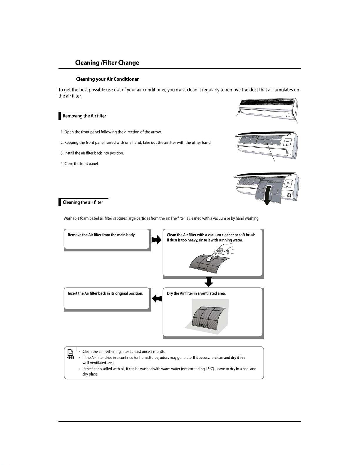
Open the front panel and remove it.
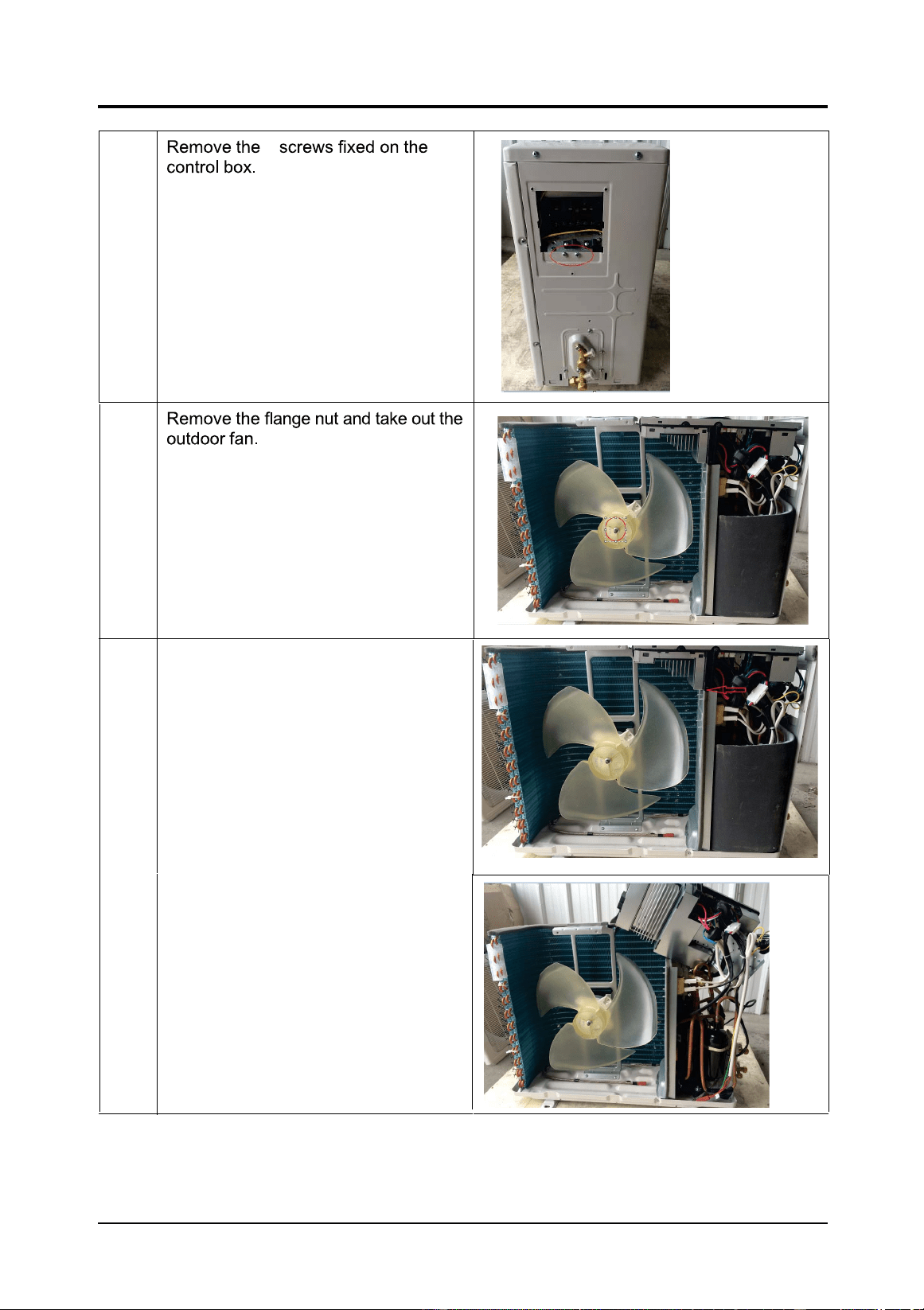
Remove screw fixing on the
terminal cover.
Remove the terminal coverDQG
V
HFXULW\FRYHU.
Slide out the 2 air filters.
AAR09JSALBWKNCV (115V)
AR09JSFLBWKNCV(230V)
AR12JSALBWKNCV (115V)
AR12JSALBWKNCV (230V)
4-3
4-4
4-5
4-6
4-7
Open the front panel and remove it.
Remove screw fixing on the
terminal cover.
Remove the terminal cover
Slide out the 2 air filters.
AAR18JSFLBWKNCV(230V)
4-8
4-9
4-10
4-
4-12
Open the front panel and remove it.
Remove screw fixing on the
terminal cover.
Remove the terminal cover
Slide out the 2 air filters.
AAR24JSFLBWKNCV(230V)
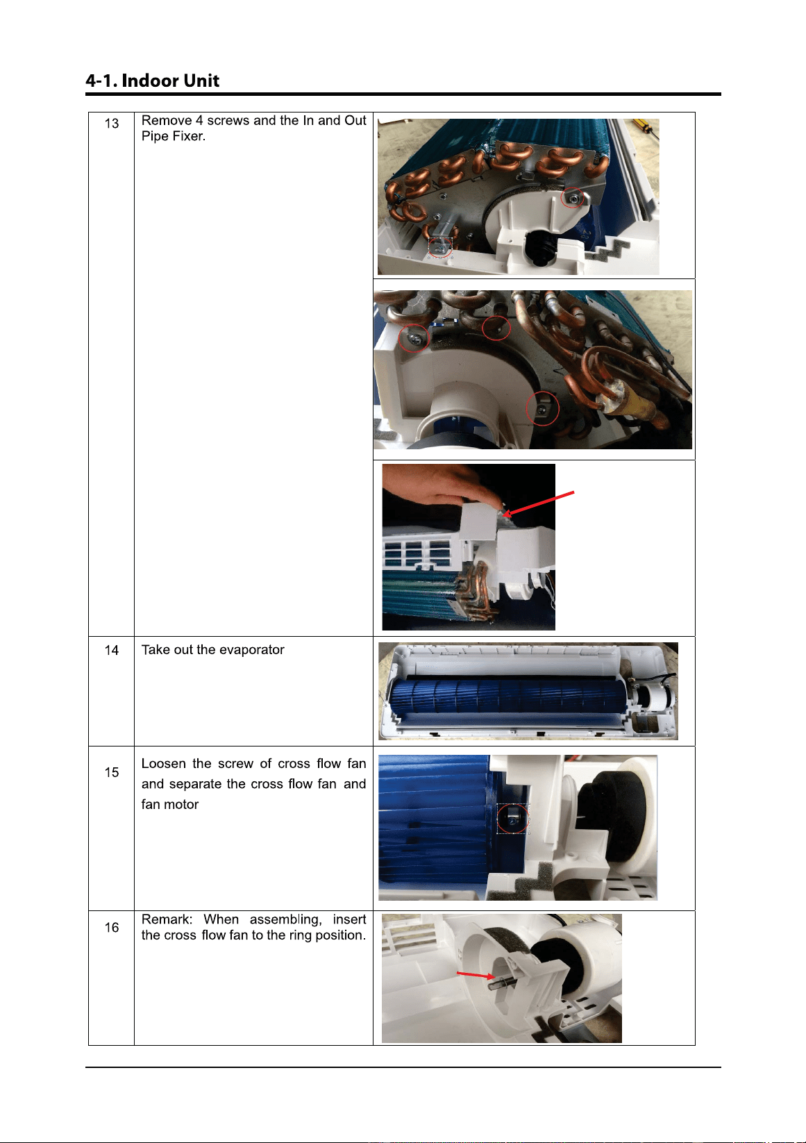
4-13
4-14
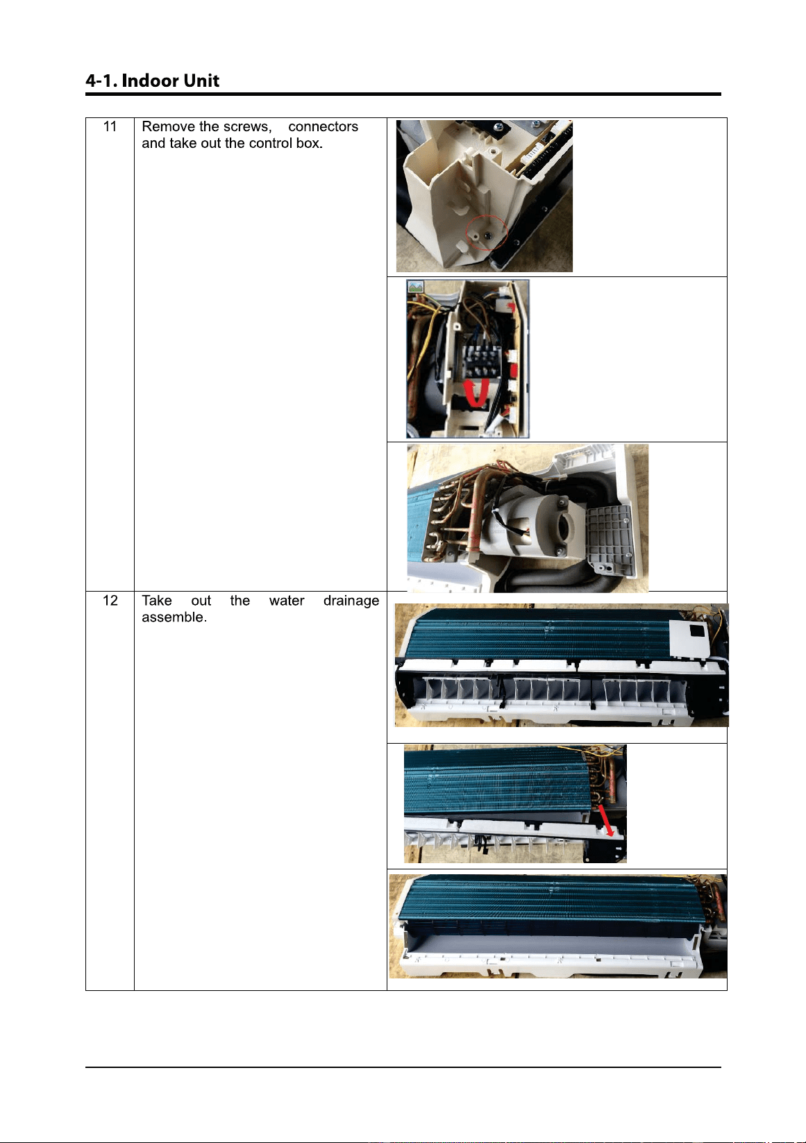
4-15
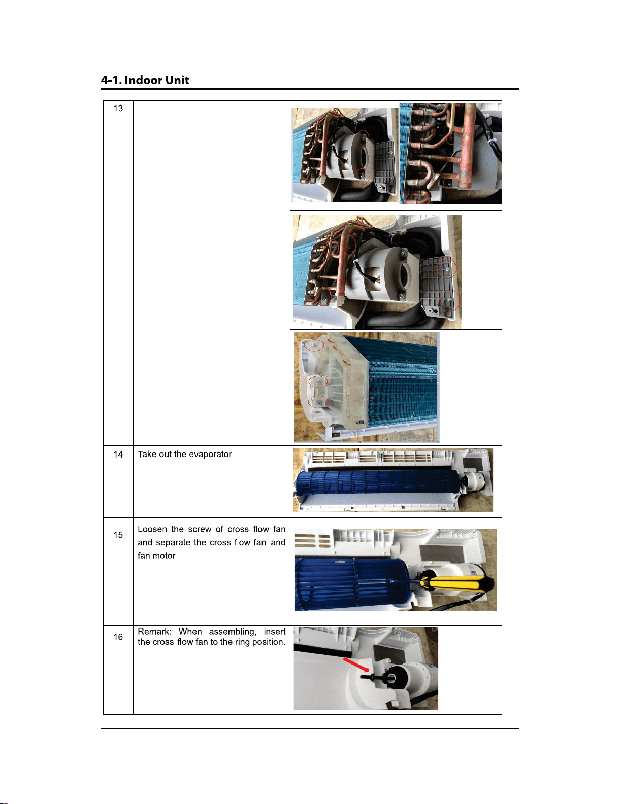
4-16
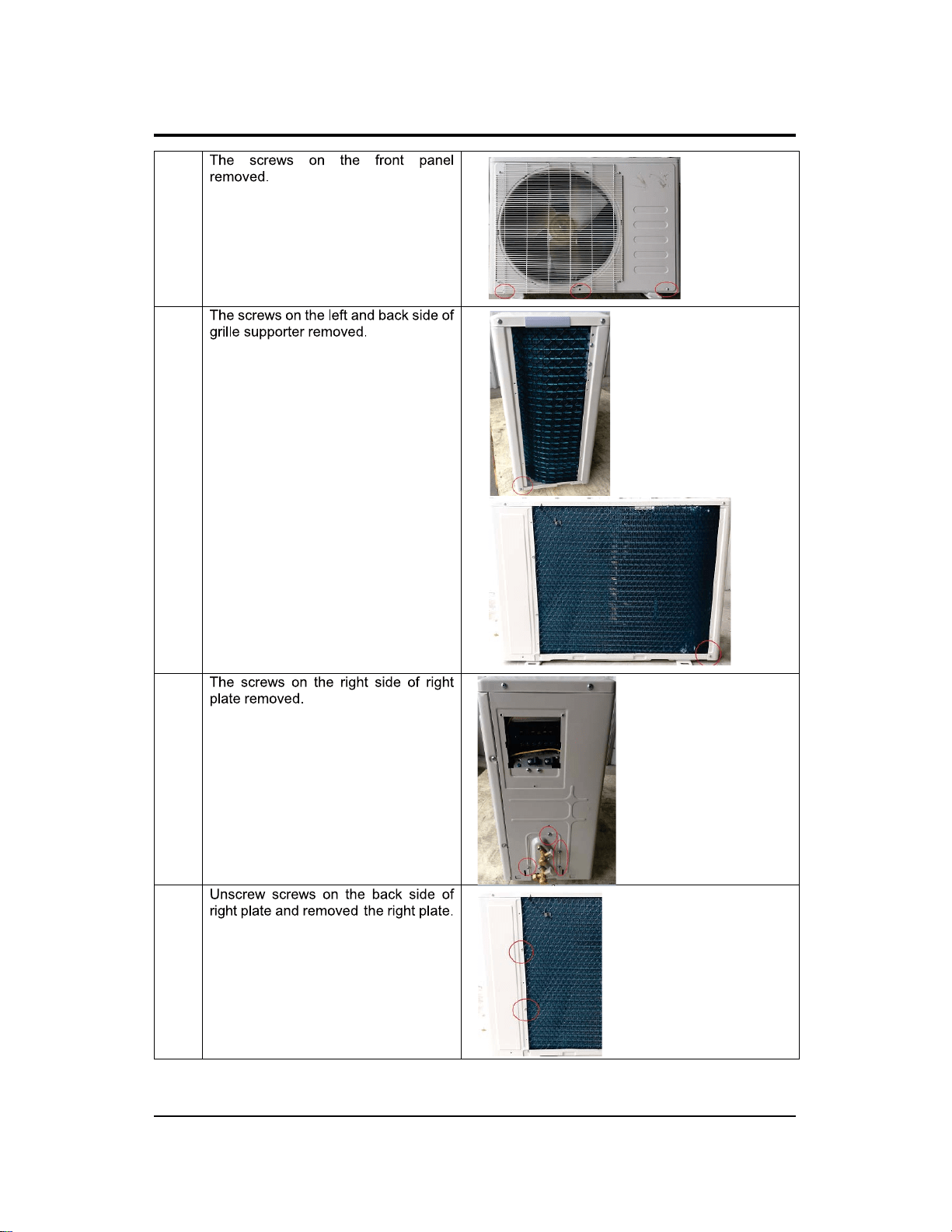
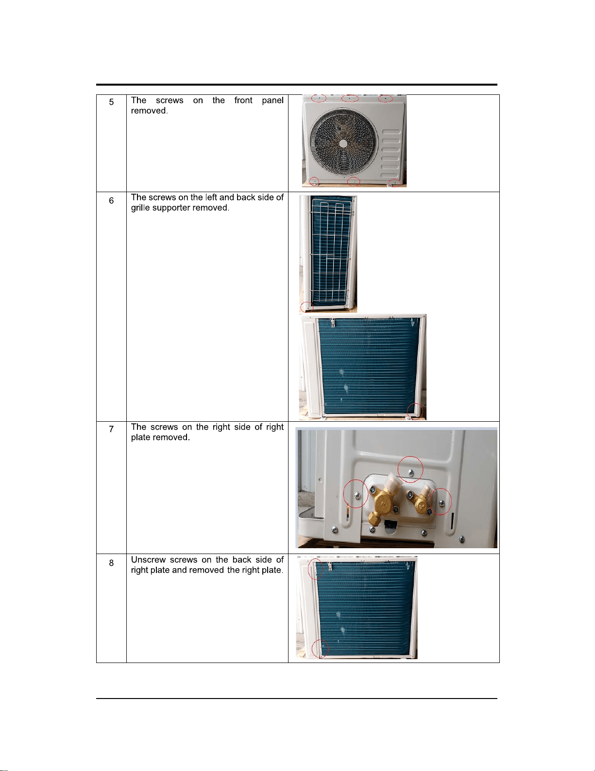
Remove the 12 screws
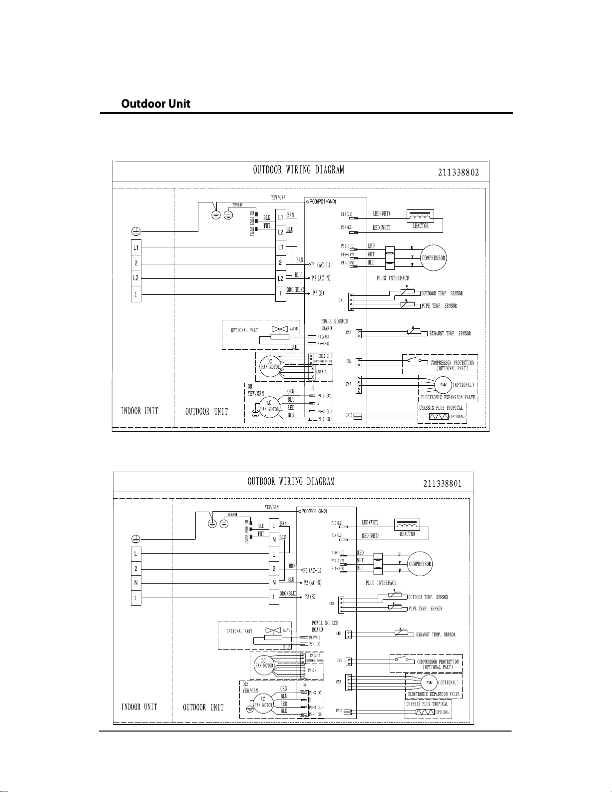
4-2. Outdoor Unit
4-17
AAR09JSALBWKNCV (115V)
AR09JSFLBWKNCV(230V)
AR12JSALBWKNCV (115V)
AR12JSALBWKNCV (230V)
4-2. Outdoor Unit
4-18
44
5
6
7
4-19
4-2. Outdoor Unit
10
R
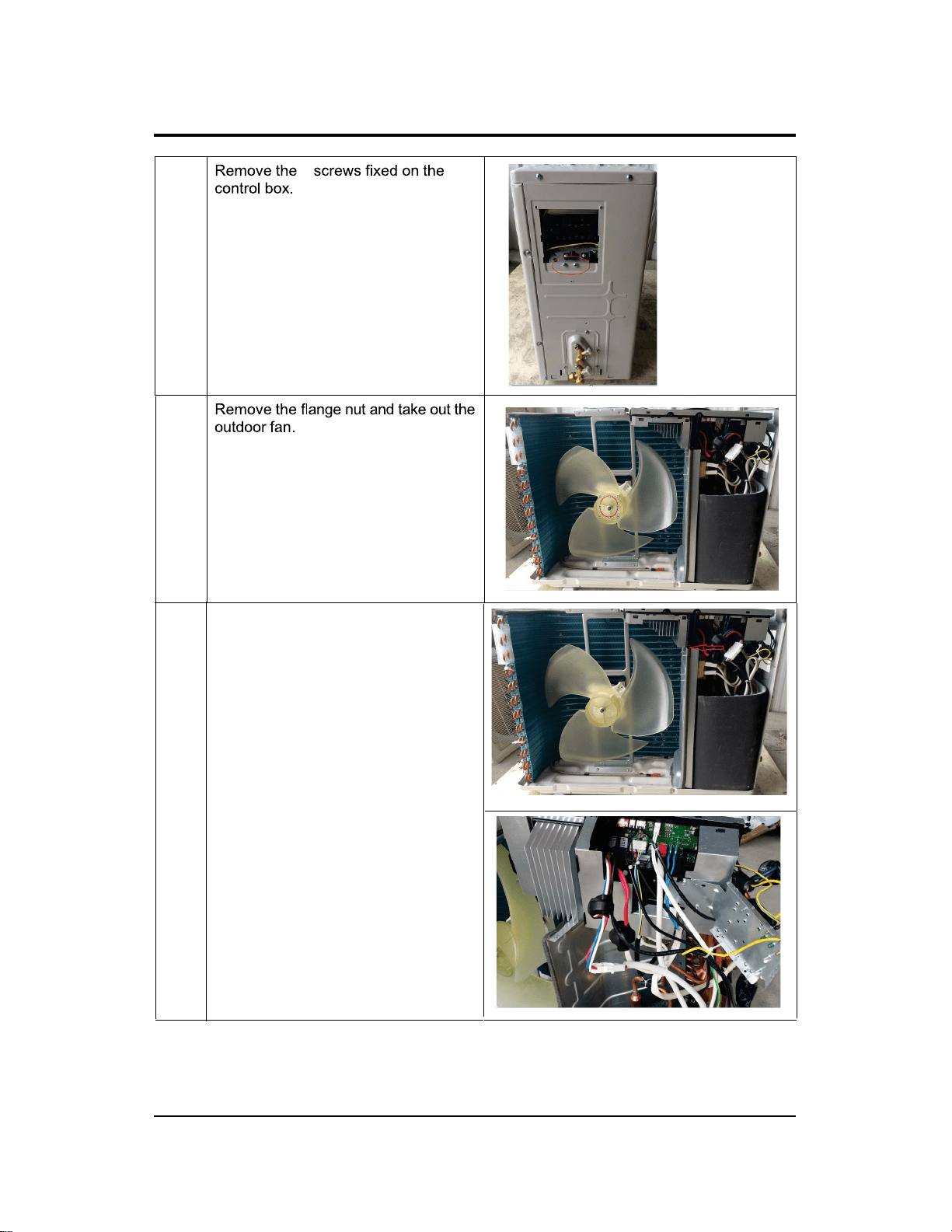
Remove the screw fixing the PCB box
8
9

4-2. Outdoor Unit
4-20
AAR18JSFLBWKNCV(230V)
4-2. Outdoor Unit
4-21
44
5
6
7
4-22
4-2. Outdoor Unit
10
R
Remove the screw fixing the PCB box
8
9
4-2. Outdoor Unit
4-23
AAR24JSFLBWKNCV(230V)
4-2. Outdoor Unit
4-24

4-25
4-2. Outdoor Unit
11
R
Remove the screw fixing the PCB box
5
5-1
5-1
ZϬϵ/12/18/24
ZϬϵ(115V)
5-2
5-2
ZϬϵ(115V)
ZϬϵ/12/18/24
6
6-1
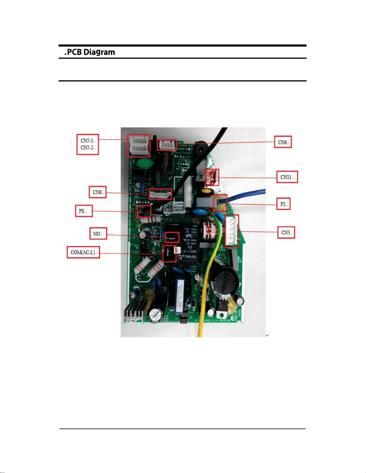
6-1 Indoor main PCB--9k/12k
6-2
6-1 Indoor main PCB--9k/12k
#1:POWER L
#3:POWER N
#1:12V AC
#2: 12V AC
#1:AC phase control singa
#3:POWER N
#1~4 STEP MOTOR signal
#5: GND
3:POWER L (OUT)
1# POWER L (OUT)
#1:Motor start capacitor
#3:AC phase control singal
#5:Power N
#1:signal of communication
#1:RT_TEMP
#2~3:GND
#4:IPT_TEMP
1#POWER L (IN)
#1:POWER N
#2:POWER N
#1:DC 5V
#2:Feedback signal input
CN7:DISPLAY
#1:+5V
#2:GND
#3:REC
#4:LED1
#5:LED2
#6:LED3
#7:KEY
#8:CLK
#9:DATA
#1:DC 5V
#2:Feedback signal input
#3:GND
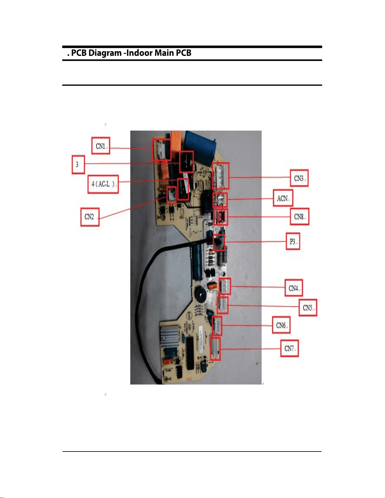
CN1:transformer IN
4(AC-L):POWER L (IN)
CN2:transformer OUT
CN3:AC-MOTOR
ACN:POWER N
CN8:Ion
P3:Communication line
CN4:MOTOR_F/B
CN5:STEP MOTOR
CN6:TEMPERATURE SENSOR
CN4:MOTOR_F/B
6
6-3
6-2 Indoor main PCB--18k
6-4
6-2 Indoor main PCB--18k
#1:POWER N
#1:AC phase control singa
#3:POWER N
SENSOR
#1:RT_TEMP
#2~3:GND
#4:IPT_TEMP
NO:POWER L (OUT)
1# POWER L (OUT)
#1:Feedback signal input
#2 DC phase control singal
#3:+15V
#4 GND(hot)
#5:
#6 +310VDC
#1 signal of communication
1#POWER L (IN)
CN5-2:STEP MOTOR
#1 +12V
#2~5:STEP MOTOR signal
#1:GND
#2:+5V
#3:LED3
#4:LED2
#5:LED1
#6:REC
#7:DATA
#8:CLK
P2:POWER N
COM(AC-L):POWER L (IN)
CN11:Ion
CN3:DC-MOTOR
CN5-1:STEP MOTOR
CN6:TEMPERATURE
PS:Communication line
CN8:DISPLAY
6
6-5
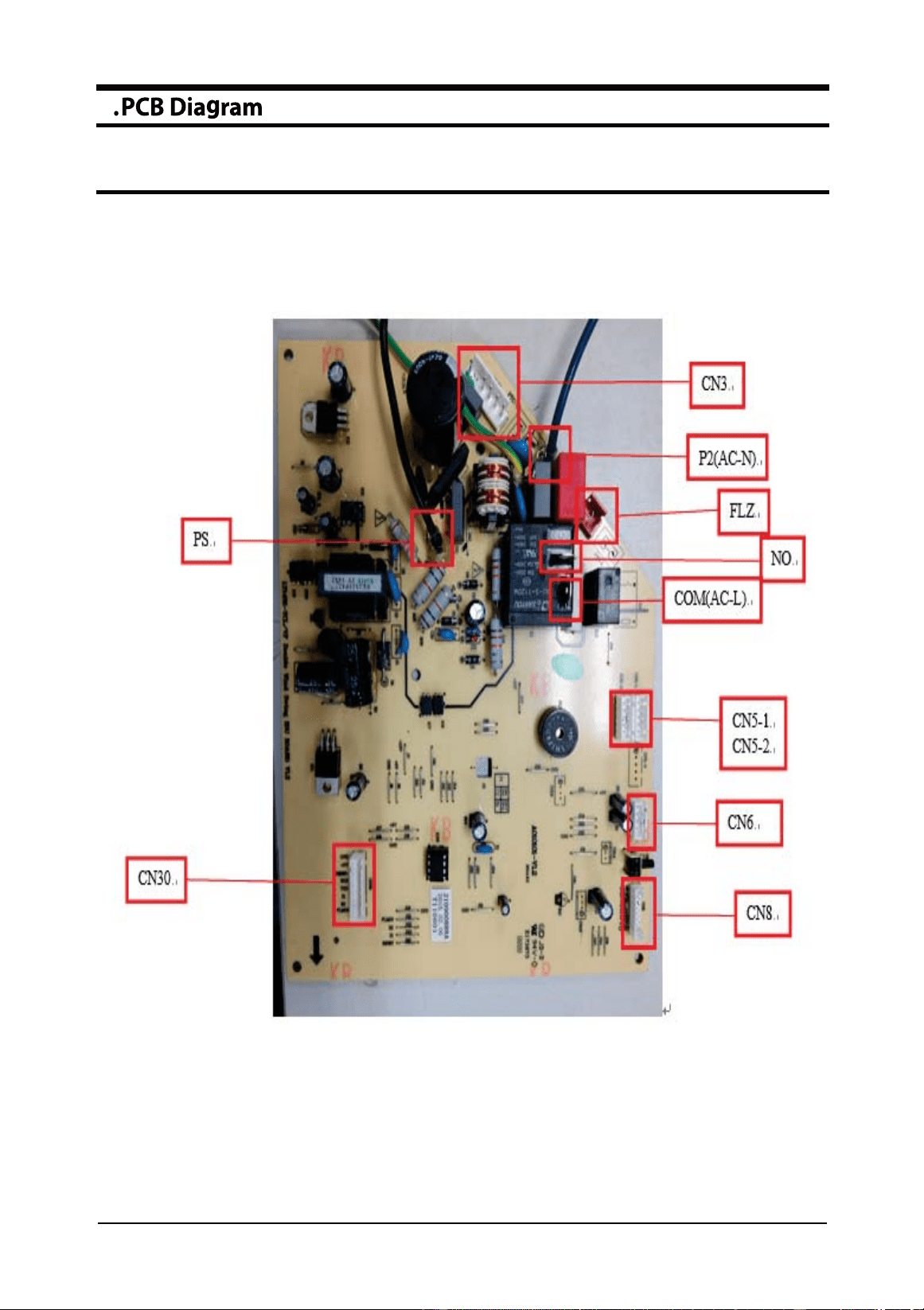
6-3 Indoor main PCB--24k
6-6
6- Indoor main PCB--24k3
CN5-2:STEP MOTOR
#1 +12V
#2~5:STEP MOTOR signal
#1:RT_TEMP
#2~3:GND
#4:IPT_TEMP
#1:AC phase control singa
#3:POWER N
NO:POWER L (OUT)
1# POWER L (OUT)
#1:Feedback signal input
#2 DC phase control singal
#3:+15V
#4 GND(hot)
#5:
#6 +310VDC
#1 signal of communication
1#POWER L (IN)
#1:POWER N
#2:POWER N
#1:GND
#2:+5V
#3:RESET
#4:RXD
#5:TXD
#6:X1
#7:X2
#8:FLMD0
CN5-1:STEP MOTOR
COM(AC-L):POWER L (IN)
CN6:TEMPERATURE SENSOR
CN3:DC-MOTOR
P2(AC-N):POWER N
FLZ:Ion
P3:Communication line
CN30:Programmer port
#1:GND
#2:+5V
#3:LED
#4:SHI
#5:GE
#6:REC
#7:SDA
#8:CLK
CN8:DISPLAY
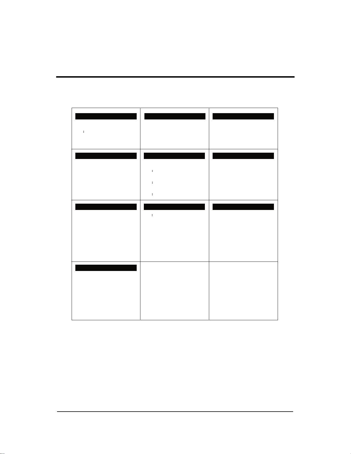
6-7
6-
Indoor display PBA-ϵ<ϭϮK
ϰ
#1:+5V
#2:GND
#3:REC
#4:LED1
#5:LED2
#6:LED3
#7:KEY
#8:CLK
#9:DATA
CN8:DISPLAY
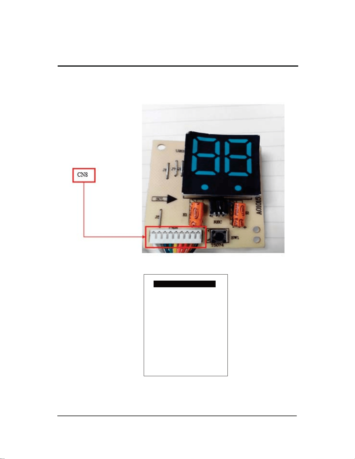
6-
Indoor display PBA-18KϮϰ<
6-8
5
#1:GND
#2:+5V
#3:LED
#4:SHI
#5:GE
#6:REC
#7:SDA
#8:CLK
CN8:DISPLAY
7
7-1
7-1
8-1
8
8-1
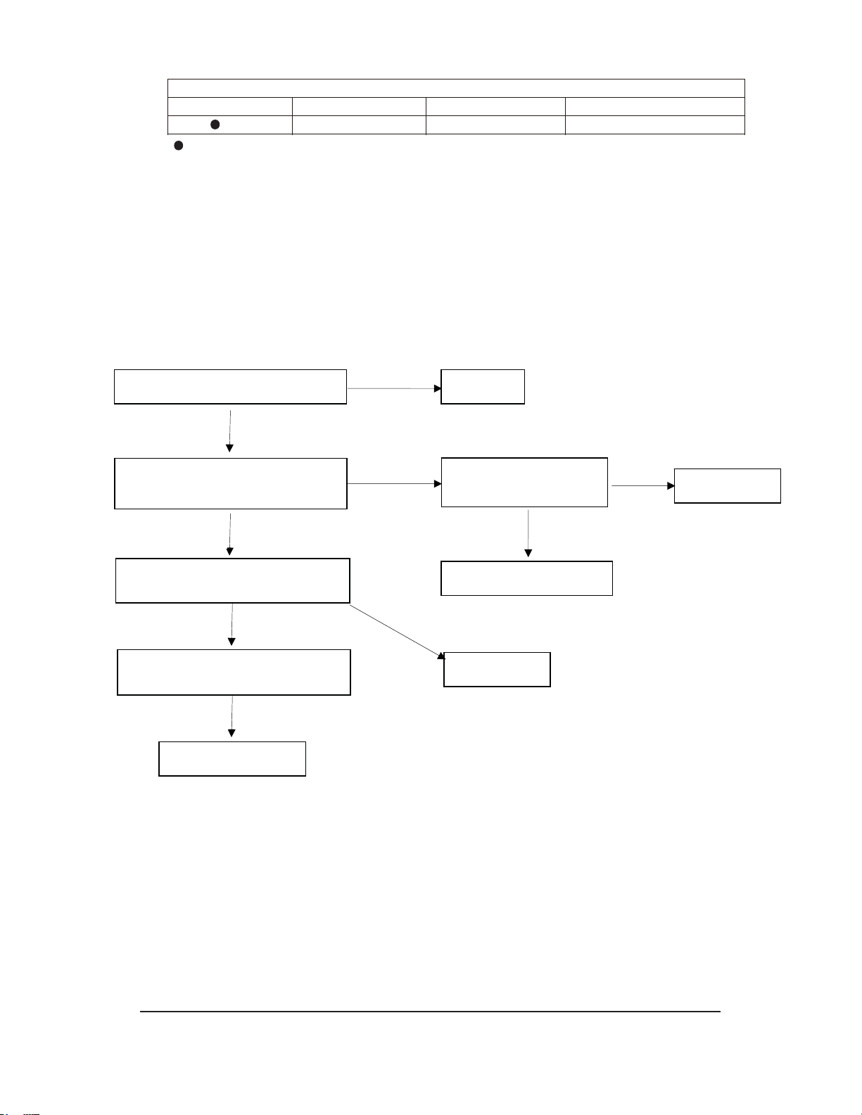
7URXEOHVKRRWLQJSURFHGXUH
$QDO\VLV
(QHUJL]HDQGREVHUYHIRUDURXQGPLQXWHV,I(LVDOZD\VGLVSOD\HG:
D 7LJKWRUFRUUHFWZLULQJFRQQHFWLRQEHWZHHQLQGRRUDQGRXWGRRU"
7KHWHUPLQDO/DQG1VKDOOFRUUHVSRQGWRHDFKRWKHURQLQGRRUDQGRXWGRRUXQLWV0HDVXUH
WKHYROWDJHRQRXWGRRUWHUPLQDO/DQG1,IWKHYROWDJHLV³´UHSODFHWKHLQGRRUPDLQ
3&%
E ,IWKH/1YROWDJHLVQRUPDOPHDVXUHWKHYROWDJHEHWZHHQWKHRXWGRRUWHUPLQDO1DQG
,IWKHYROWDJHFKDQJHRFFXUVEHWZHHQa9FKDQJHSXOVHYROWDJHUHSODFHWKHLQGRRU
PDLQ3&%,IWKHYROWDJHFKDQJHRFFXUVEHWZHHQa9FKDQJHSXOVHYROWDJHEXWWKHUH
LVQR9UHSODFHWKHRXWGRRUSRZHUVRXUFHERDUG
F ,IWKH/1YROWDJHLVQRUPDOPHDVXUHWKHYROWDJHEHWZHHQWKHRXWGRRUWHUPLQDO1DQG
,I WKH YROWDJH KDV QRFKDQJH)LUVWO\ UHSODFH WKH LQGRRUPDLQ3&% ,I WKH IDXOW UHPDLQV
XQVROYHGUHSODFHWKHRXWGRRUSRZHUVRXUFHERDUG
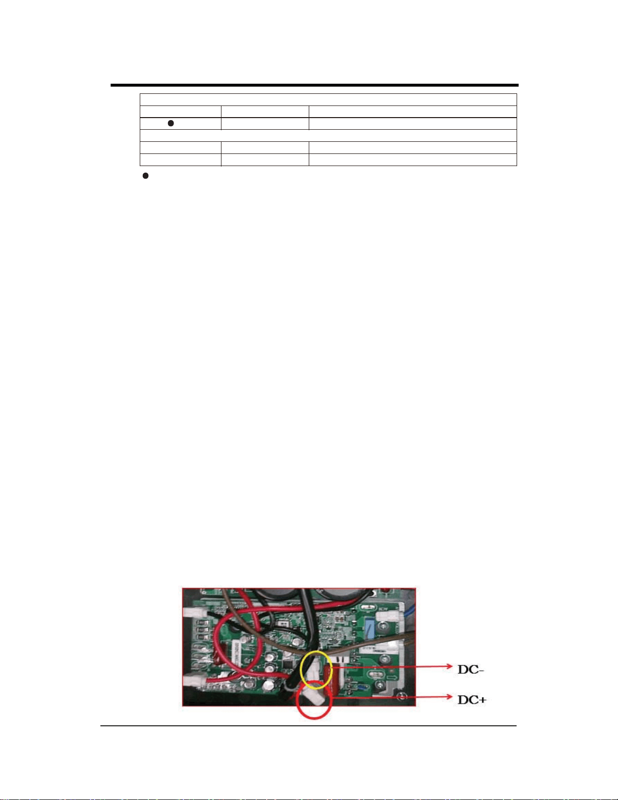
G ,QGLFDWRURQRXWGRRUSRZHUVRXUFHERDUG
&KHFNLI3)&ERDUGLVEXUQW,ILWLVUHSODFH3)&ERDUG
,IQRGDPDJHWHVWWKH'&YROWDJHEHWZHHQ'&DQG'&,IWKHYROWDJHLV
DURXQG9UHSODFHWKHSRZHUVRXUFHERDUG
,IQRGDPDJHWHVWWKH'&YROWDJHEHWZHHQ'&DQG'&,IWKHYROWDJHLV9
UHSODFHWKH3)&ERDUG
8-2
!"
#$!!$
%
&
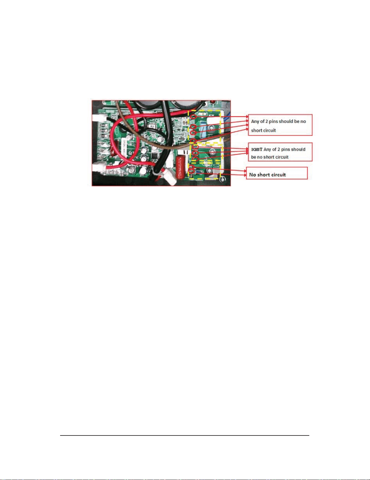
H ,VWKHUH
DQ\EXUQWDSSHDUDQFHRQ3&%" ,IQRWHVWWKHUHFWLILHU)5',*%7HWFLIDQ\
FRPSRQHQWEURNHQUHSODFHWKHERDUG
I,IWKHSUREOHPFDQQRWEHVROYHGE\XVLQJWKHPHWKRGVDERYH)LUVWO\UHSODFHWKHLQWHOOLJHQW
SRZHUPRGXOH,IWKHSUREOHPUHPDLQVXQVROYHGUHSODFHWKHLQGRRUPDLQ3&%SRZHUVRXUFH
ERDUGDQG3)&ERDUG
8-3
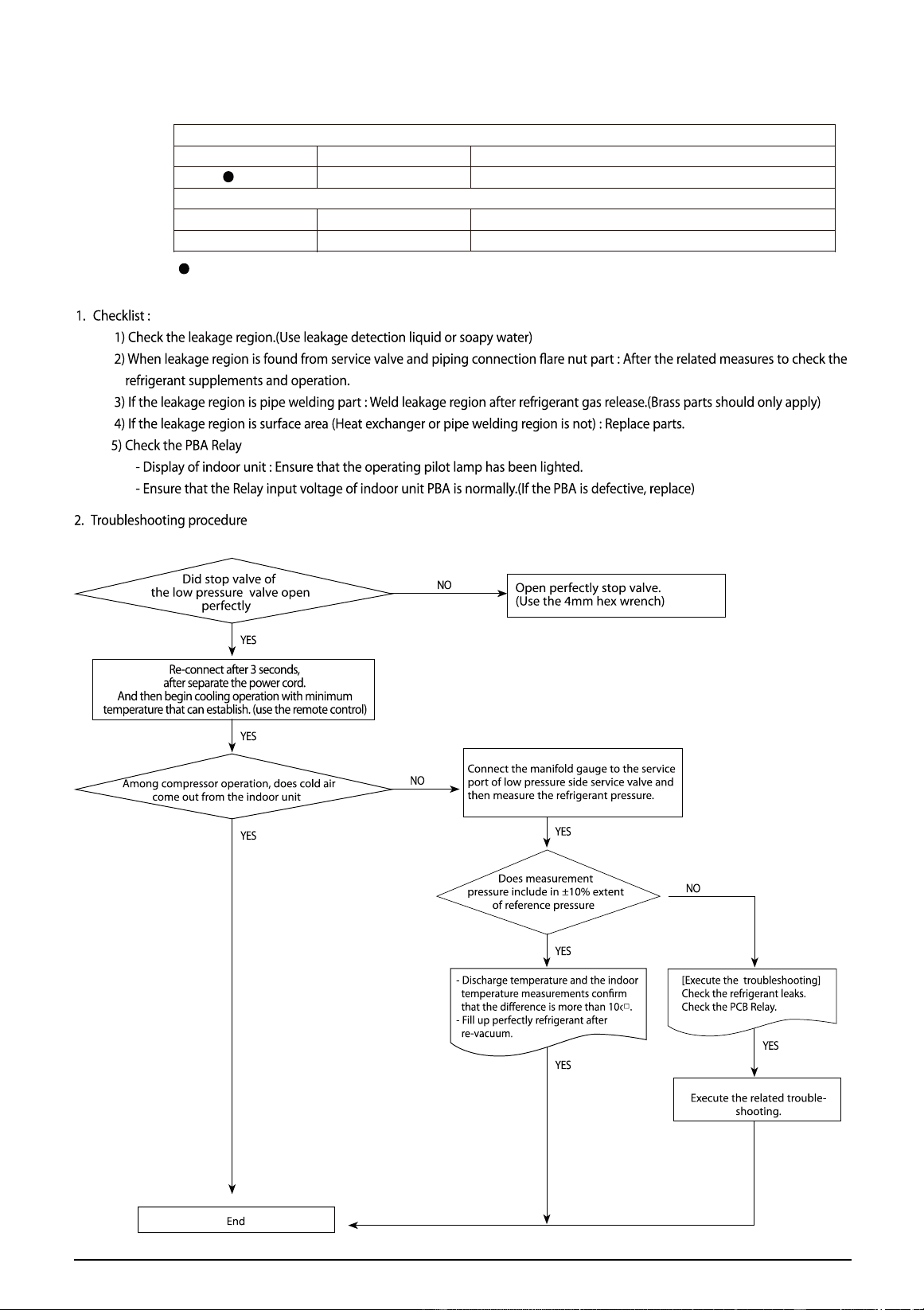
$ &KHFNOLVW
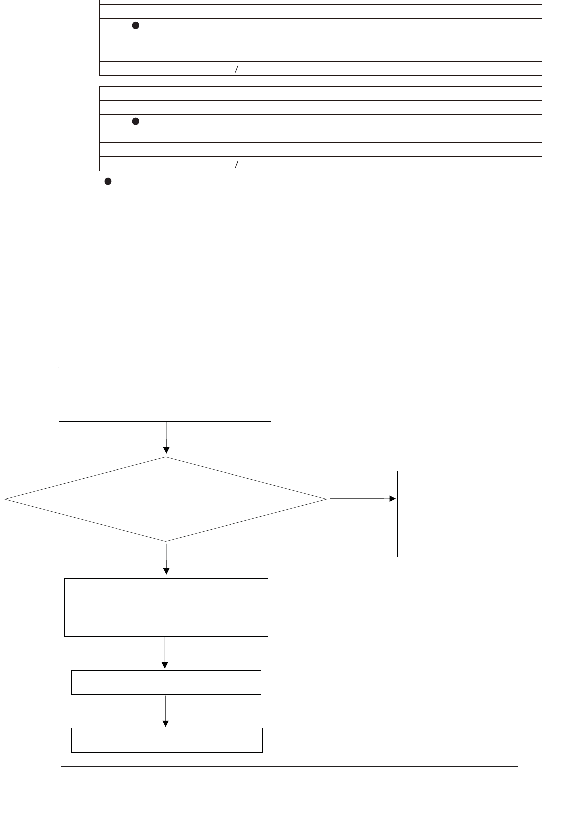
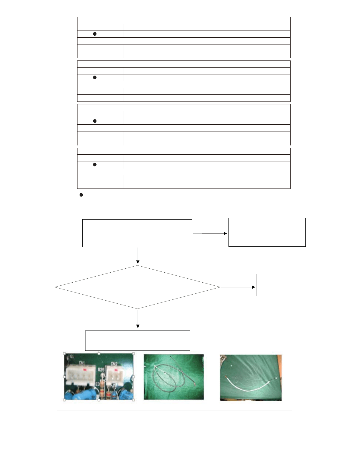
D ,VWKHLQGRRUXQLWVWHPSHUDWXUHVHQVRUFRQQHFWHGFRUUHFWO\"
E ,VWKHVHQVRUSODFHGFRUUHFWO\"
F 'RHVWKHVHQVRUVDWLVI\WKHUHVLVWDQFHYDOXHLQDFFRUGDQFHZLWK
WHPSHUDWXUH"
% 7URXEOHVKRRWLQJSURFHGXUH
8-4
Detach the assembled sensor from the PCB sensor
connector and measure the sensor resistance with
ohmmeter(tester)
,VWKHVHQVRUUHVLVWDQFHYDOXH
NRKPfDWWKHURRPWHPSHUDWXUH
Replace the sensor
Sensor resistance value : 20°C- 6.0836kohm
30°C - 4.1331kohm
35°C -3.4352kohm
40°C- 2.8699kohm
Connect the sensor to PCB connector (4pin in)
supply power and measure the voltage of the
connector accordingly
Below 0.5V or Over 4.5V
Replace the PCB
NO
YES
RIe&
!"
!!# "$
%&
%
!"
!# "$
%'
$ &KHFNOLVW
,VWKHLQGRRUXQLWIDQPRWRUFRQQHFWHGSURSHUO\"
,VWKH$&SRZHUVXSSO\YROWDJHFRUUHFW"
% 7URXEOHVKRRWLQJSURFHGXUH
8-5
Is capacity of fan motor capacitor ok
Check the winding of motor accordingly
NO
YES
Replace it
Is there outlet of fan connector(speed
accordingly)
Is the relay accordingly or
controller silicon ok
Replace it
Replace PCB
Replace it
Is running of motor shaft smooth
Replace it
NO
NO
YES
YES
YES
NO
NO
!" #
"
$%
7URXEOHVKRRWLQJ
8-6
*RRGFRQQHFWLRQDFFRUGLQJO\"
&RQQHFWLWZHOO
5HSODFH
5HS
ODF3&%DFFRUGLQJO\
12
<(6
<(6
12
6HQVRUUHVLVWDQFH23(1"6+257"
RU'5,))
!" #
"$ !#
%&
'
(
!" #
!" #
"$)*! *"
#
"$
*
+ "$
"
,
%%
%-./&
&KHFNOLVW
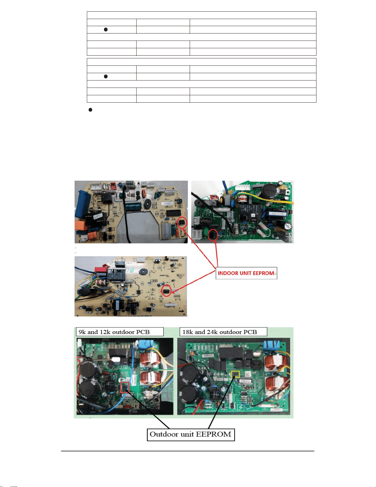
D &KHFNZKHWKHUWKH((3520LVORRVHRUQRW
E ,IWKHLQVWDOODWLRQLVJRRGUHSODFHWKHLQGRRUPDLQ3&%
F ,IWKHIDXOWUHPDLQVXQVROYHGDIWHUUHSODFHPHQWRIWKHLQGRRUFRQWUROERDUG
UHSODFHRXWGRRUSRZHUVRXUFHERDUG
8-7
!"
#$
!"
%
&'(#)
7URXEOHVKRRWLQJ
8-8
*RRGFRQQHFWLRQ"
&RQQHFWLWZHOO
5HSODFH
5HS
O
D
F3&%DFFRUGLQJO\
12
<(6
<(6
12
'&IDQPRWRURNVKDIWZLQGLQJ
UHVLVWDQFH"
!"
! !"
#$%&'
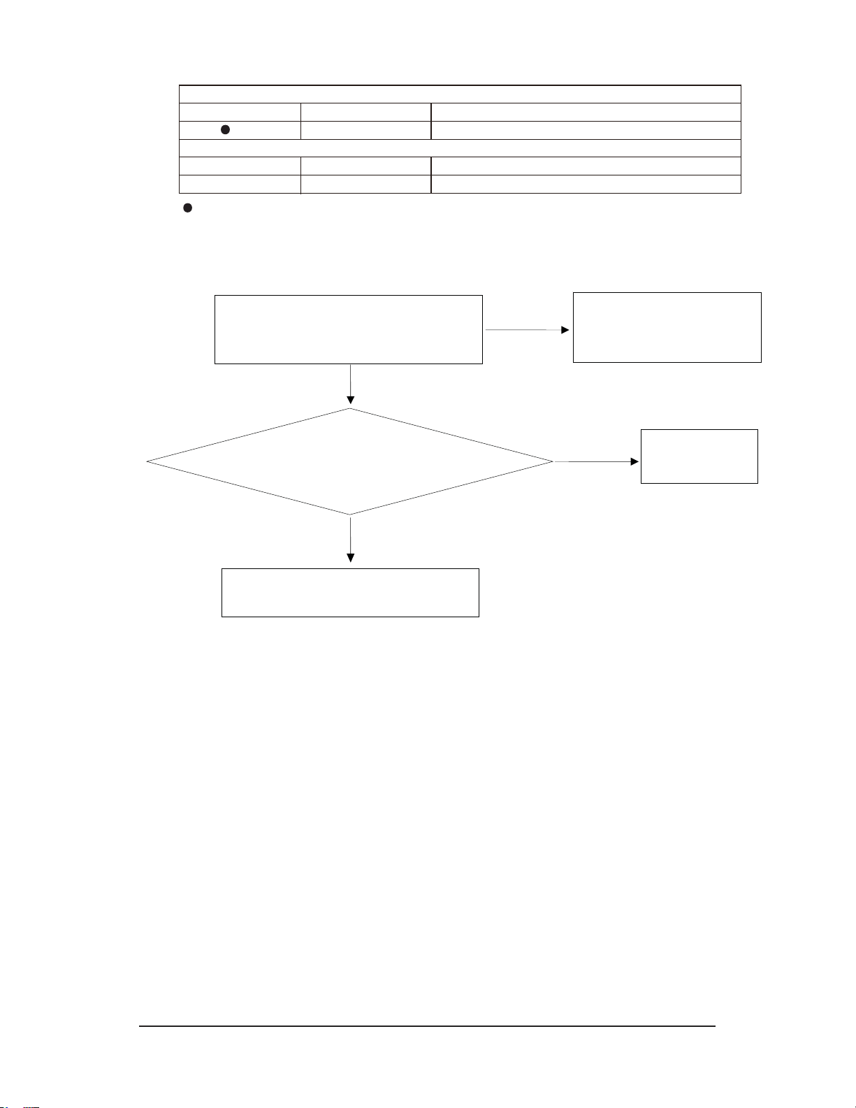
&KHFNOLVW
D ,I WKHSURWHFWLRQKDSSHQVFRPSUHVVRUVWDUWVXSIRURQO\DIHZVHFRQGRUHYHQQRW
VWDUWWRZRUNFKHFNZKHWKHUWKHFRPSUHVVRUFRQQHFWLRQLVRN
E
,IWKHSURWHFWLRQKDSSHQVLQWKHSURFHVVRI$&RSHUDWLRQFKHFNZKHWKHUYHQWLODWLRQ
LVVPRRWKRUQRW":KHWKHU,30IL[HGZHOORUQRW"$&JDVOHDNDJHRU
RYHUFKDUJH"
F ,IWKHVWHSDDQGEDOOULJKWUHSODFHRXWGRRU3&%
8-9
!"
#!$
%&
!"
#$%
&'
(
8-10
&KHFNOLV
W
Re-energize and check the protection code on display. Firstly display P0.
1
If this code is displayed when the compressor is started for several seconds or even not started, check
the compressor connection for correctness, if no insert wrong, replace outdoor PCB.
2 Check if the outdoor module is tightly installed onto the radiating fins and if the silicone is applied evenly,
fix the screws again if loose.
3 Check the system pressure, recharge refrigerant if the pressure is low, and discharge some refrigerant
if the pressure is too high.
4 Check the outdoor ventilation and if there is any obstruction that affects the normal radiating of the air
conditioner, and installation again.
5 If the above inspections are normal, but the fault remains unsolved, please replace the outdoor PCB.
Re-energize and check the protection code on display. Firstly display P9.
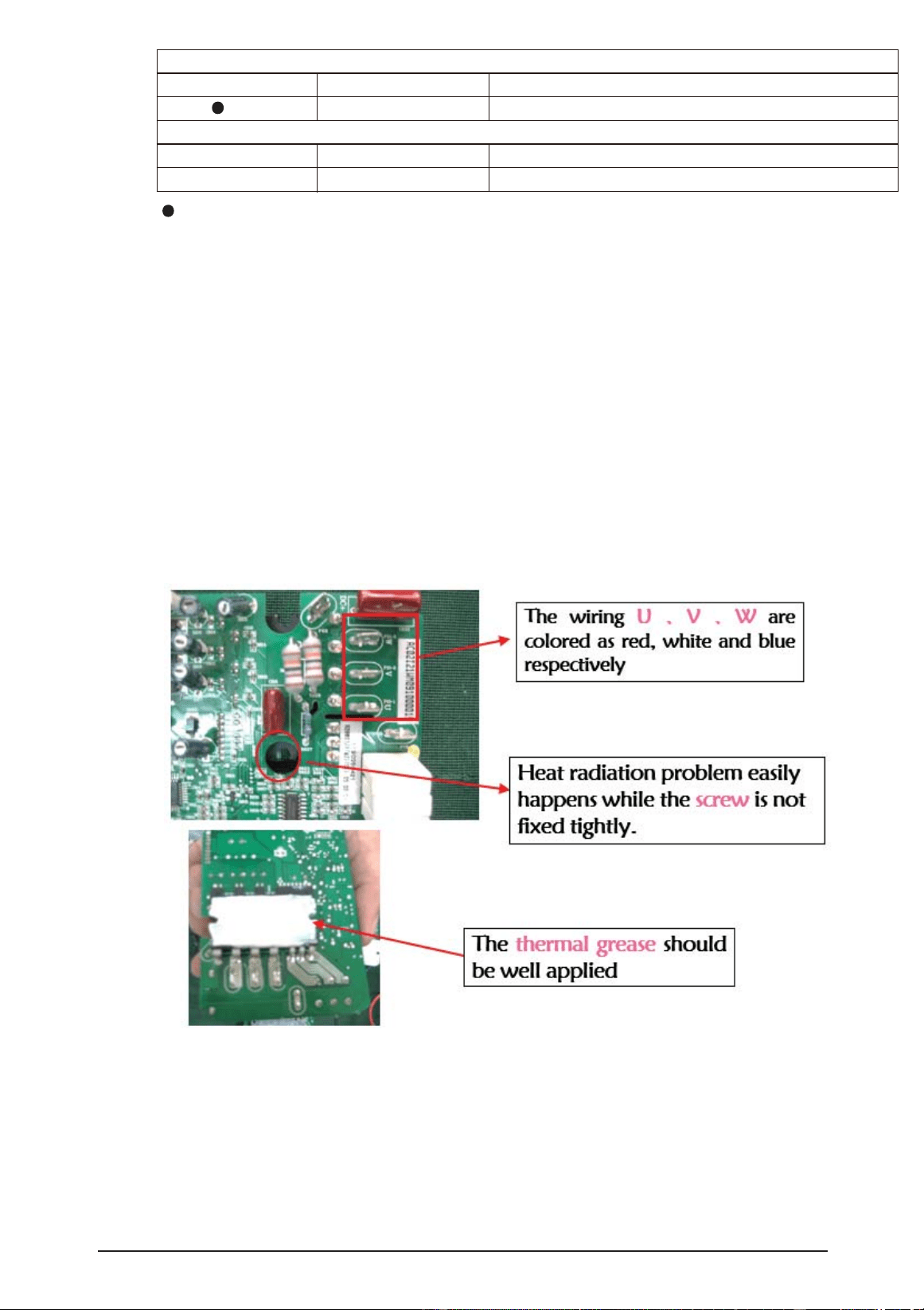
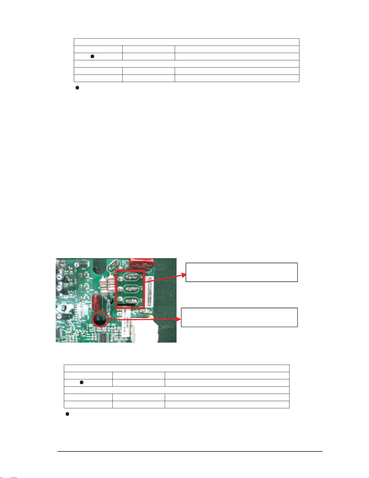
a) Check the U,V, W connection, if is correctness or loose please connect again.
b) If this code is displayed when the compressor is started for several seconds or even not started,
check the compressor connection for correctness, if no insert wrong, replace outdoor PCB.
c) When the compressor is restarted immediately after stop, this might also cause P9 protection
because the cooling system is not stable, try starting the air conditioner again after a longer period of
stop.
The wiring U,V,W are closed as red,
white and blue respectively.
Heat radiation problem easily happened
while the screw is not fixed tightly.
LED DISPLAY
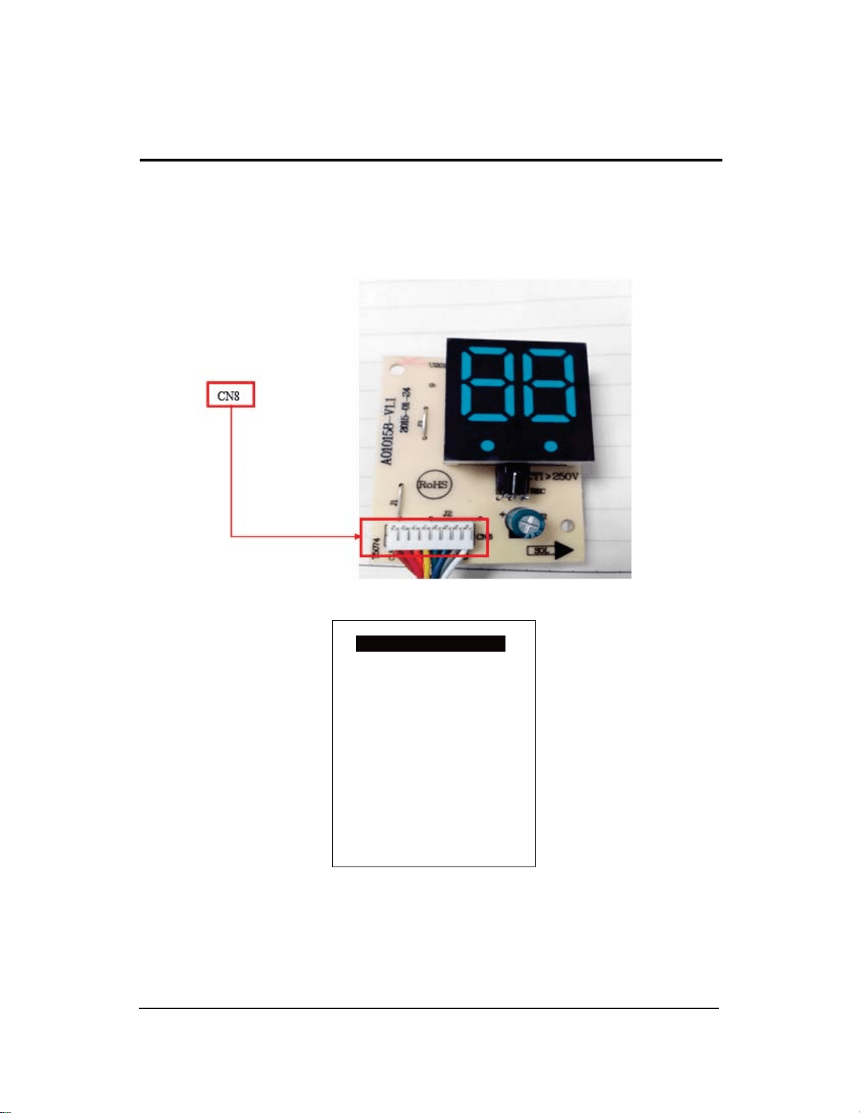
Indoor display
Indoor Display of LED
DESCRIPTION
LED DISPLAY
Outdoor display
Outdoor unit LED Flashes (times)
Compressor frequency drive fault
30
LED ON
Outdoor display of LED
E9
//
Indoor display
Indoor Display of LED
DESCRIPTION
LED DISPLAY
Outdoor display
Voltage sensor fault
13
LED ON
Outdoor display of LED
EU
//
1
&DXVH9ROWDJHVHQVRUIDXOW
6ROXWLRQ3OHDVHUHSODFHRXWGRRU3&%
LED DISPLAY
Outdoor unit LED Flashes (times)
8-1
8-3
8-3-1
8-3-2
8-3-3
8-1
No
9.
9-1
9-1
9-2
9-2
9-2-1
9-2-2
9-2-3
9-3
9-2-4
9-4
10-3
10-2
10-3
10-3
10-4
10-3
10-4
10-4-1
10-5
10-5
10-5-1
10-5-2
10-6
10-6
10-6-1
10-7
N/X
10-7
10-8
AR12JSFLBWK C V
INVERTER CO
INVERTER HP
S
V
KCV CV