
MSZ-FE18NA
>
MITSUBISHI
MSZ-GE24NA
497%
ELECTRIC
MSY-GE24NA
SPLIT-TYPE
AIR
CONDITIONERS
INSTALLATION
MANUAL
installation.
JG79A344H03
When
installing
multi
units,
refer
to
the
instal-
lation
manual
of
the
multi
unit
for
outdoor
unit
Required
Tools
for
Installation
Phillips
screwdriver
5/32
in.
(4
mm)
hexagonal wrench
Level
Flare
tool
for
R410A
Scale
Gauge
manifold
for
R410A
Utility
knife
or
scissors
Vacuum
pump
for
R410A
3
in.
(75
mm)
hole
saw
Charge
hose
for
R410A
Torque
wrench
Pipe
cutter
with
reamer
Wrench
(or
spanner)
1.
BEFORE
INSTALLATION
1-1.
THE
FOLLOWING
SHOULD
ALWAYS
BE
OBSERVED
FOR
SAFETY
Be
sure
to
read
these
safety
precautions
and
instructions.
Be
sure
to
observe
the
warnings
and
cautions
specified
here.
After
reading
this
manual,
be
sure
to
store
it
with
the
OPERATING
INSTRUCTIONS
for
future
reference.
Please
report
to
your
supply
authority
or
obtain
their
consent
before
connecting
this
equipment
to
the
power
supply
system.
A
WARNING
(Could
lead
to
death
or
serious
injury.)
Do
not
install
the
unit by
yourself
(user).
Improper
or
incomplete
installation
could
cause
fire,
electric
shock,
injury
due
to
the
unit falling,
or
water
leakage.
Consult
a
qualified
installer
or
the
dealer
from
whom
you
purchased
the
unit.
Follow
the
instructions
detailed
in
the
installation
manual.
Incomplete
installation
could
cause
fire
or
electric
shock,
injury
due
to
the
unit
falling,
or
leakage
of
water.
When
installing
the
unit,
use
appropriate
protective
equipment
and
tools
for
safety.
Failure
to
do
so
could
cause
injury.
Install
the
unit
securely
in
a
place
that
can
bear
the
weight
of
the
unit.
If
the
installation
location
cannot
bear
the
weight
of
the
unit,
the
unit
could
fall
causing
injury.
Perform
electrical
work
according
to
the
installation
manual
and
be
sure
to
use
an
exclusive
circuit.
Do
not
connect
other
electrical
appliances
to
the
circuit.
If
the
capacity
of
the
power
circuit
is
insufficient
or
there
is
incomplete
electrical
work,
it
could
result
in
a
fire
or
an
electric
shock.
Ground
the
unit
correctly.
Do
not
connect
the
ground
wire
to
a
gas
pipe,
water
pipe,
lightning
rod
or
telephone
ground.
Defective
grounding
could
cause
electric
shock.
Do
not
damage
the
wires.
Damaged
wires
could
cause
fire.
Be
sure
to
shut
off
the
main
power
when
setting
up
the
indoor
P.C.
board
or
wiring.
Failure
to
do
so
could
cause
electric
shock.
Use
the
specified
wires
to
securely
connect
the
indoor
and
outdoor
units.
At-
tach
the
wires
firmly
to
avoid
applying
stress
to
the
terminal
block.
Improper
connection
could
cause
fire.
Do
not
install
the
unit
in
a
place
where
flammable
gas
may
leak.
If
gas
leaks
and
accumulates
around
the
unit,
it
could
cause
an
explosion.
Do
not
use
intermediate
connection
of
the
power
cord
or
the
extension
cord.
Do
not
connect
many
devices
to
one
AC
outlet.
it
could
cause
a
fire
or
an
electric
shock.
Use
the
parts
provided
or
specified
parts
for
the
installation
work.
The
use
of
defective
parts
could
cause
an
injury
or
leakage
of
water
due
to
a
fire,
an
electric
shock,
the
unit
falling,
etc.
When
plugging
the
power
supply
plug
into
the outlet,
make
sure
that
there
is
no
dust,
blockage,
or
loose
parts
both
in
the
outlet
and
on
the
plug.
Verify
that
the
power
supply
plug
is
completely
in
the
outlet.
If
there
is
dust,
blockage,
or
loose
parts
on
the
power
supply
plug
or
the
outlet,
it
could
cause
electric
shock
or
fire.
If
loose
parts
are
found
on
the
power
supply
plug,
replace
it.
Depending
on
the
installation
area,
install
a
Ground
Fault
Interrupt
(GFI)
circuit
breaker.
If
the
Ground
Fault
Interrupt
(GFI)
circuit
breaker
is
not
installed,
an
electric
shock
Do
not
install
the
outdoor
unit
where
small
animals
may
live.
could
occur.
Perform
the
drainage/piping
work
securely
according
to
the
installation
manual.
lf
there
is
defect
in
the
drainage/piping
work,
water
could
drip
from
the
unit,
and
damage
household
items.
PV
cop
Ugg
te)
ee
es
ee
a
ea
eee
eens)
|
Securely
attach
the
electrical
cover
to
the
indoor
unit
and
the
service
panel
to
the
outdoor
unit.
If
the
electrical
cover
of
the
indoor
unit
and/or
the
service
panel
of
the
outdoor
unit
are
not
attached
securely,
dust,
water,
etc.
could
collect
in
the
unit
and
could
cause
a
fire
or
an
electric
shock.
When
installing,
relocating,
or
servicing
the
unit,
make
sure
that
no
substance
other
than
the
specified
refrigerant
(R410A)
enters
the
refrigerant
circuit.
Any
presence
of
foreign
substance
such
as
air
can
cause
abnormal
pressure
rise
and
may
result
in
explosion
or
injury.
The
use
of
any
refrigerant
other
than
that
specified
for
the
system
will
cause
mechanical
failure,
system
malfunction,
or
unit
breakdown.
In
the
worst
case,
this
could
lead
to
a
serious
impediment
to
securing
product
safety.
Do
not
discharge
the
refrigerant
into
the
atmosphere.
Check
that
the
refrigerant
gas
does
not
leak
after
installation
has
been
completed.
If
refrigerant
leaks
during
installation,
ventilate
the
room.
If
refrigerant
comes
in
contact
with
a
fire,
harmful
gas could
be
generated.
If
refrigerant
gas
leaks
indoors,
and
comes
into
contact
with
the
flame
of
a
fan
heater,
space
heater,
stove,
etc.,
harmful
gases
will
be
generated.
Use
appropriate
tools
and
piping
materials
for
installation.
The
pressure
of
R410A
is
1.6
times higher
than
R22.
Not
using
the
appropriate
tools
and
materials,
or
improper
installation
could
cause
the
pipes
to
burst
causing
an
injury.
When
pumping
down
the
refrigerant,
stop
the
compressor
before
disconnecting
the
refrigerant
pipes.
lf
the
refrigerant
pipes
are
disconnected
while
the
compressor
is
running
and
the
stop
valve
is
open,
air
could
be
drawn
in
and
the
pressure
in
the
refrigeration
cycle
could
become
abnormally
high,
causing
the
pipes
to
burst.
When
installing
the
unit,
securely
connect
the
refrigerant pipes
before
starting
the
compressor.
If
the
compressor
is
started
before
the
refrigerant
pipes
are
connected
and
the
stop
valve
is
open,
air
could
be
drawn
in
and
the
pressure
in
the
refrigeration
cycle
could
become
abnormally
high,
causing
the
pipes
to
burst.
Fasten
a
flare
nut
with
a
torque
wrench
as
specified
in
this
manual.
If
fastened
too
tight,
a
flare
nut
could
break
and
cause
refrigerant
leakage.
Install
the
unit
according
to
national
wiring
regulations.
Do
not
touch
the
air
inlet
or
the
aluminum
fins
of
the
outdoor
unit.
This
could
cause
injury.
If
small
animals
enter
the
unit
and
damage
its
electrical
parts,
it
could
cause
a
mal-
function,
smoke
emission,
or
fire.
Keep
the
area
around
the
unit
clean.
een
_
UL
ee
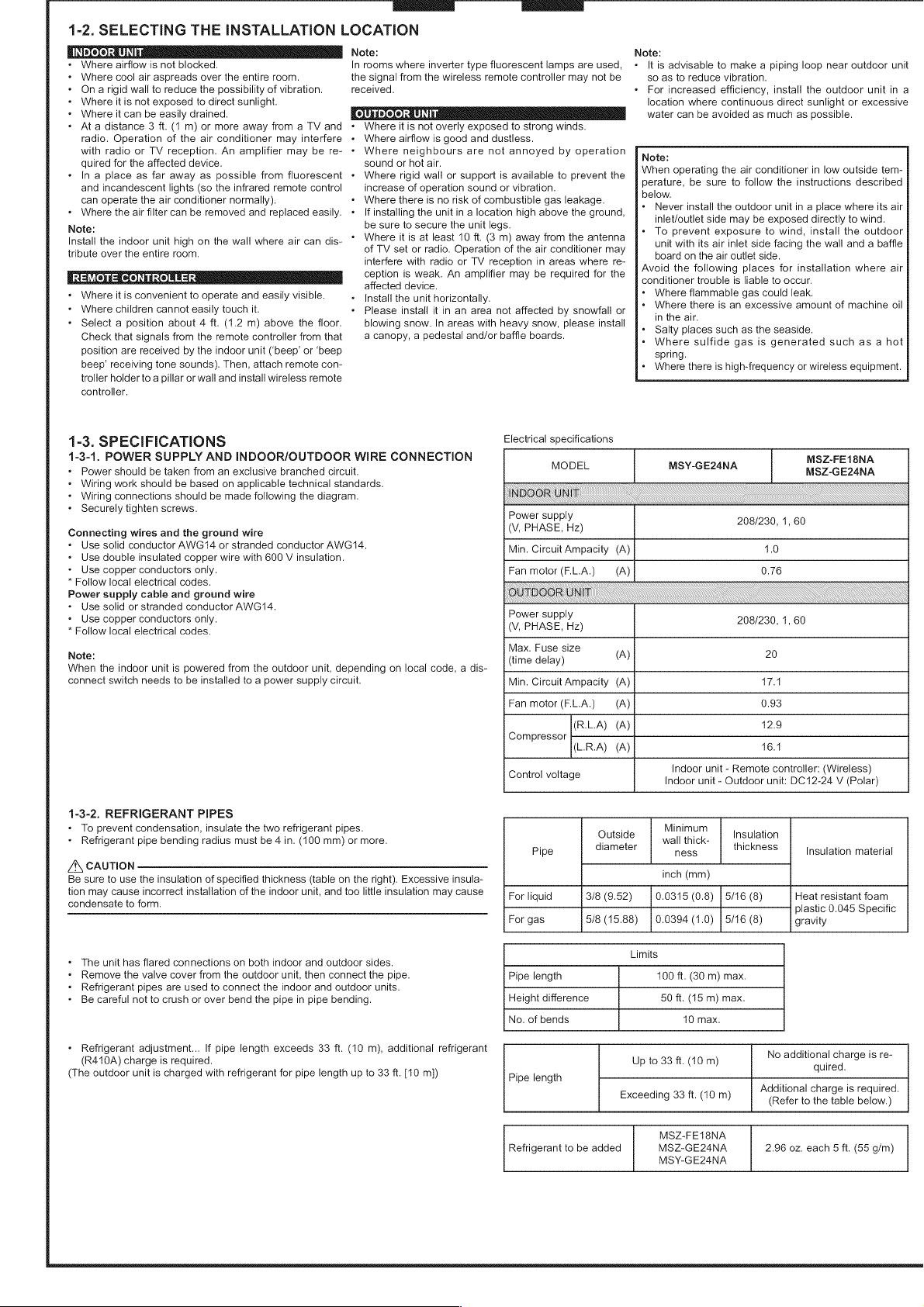
1-2.
SELECTING
THE
INSTALLATION
LOCATION
Where
airflow
is
not
blocked.
Where
cool
air
aspreads
over
the
entire
room.
On
a
rigid
wall
to
reduce
the
possibility
of
vibration.
Where
it
is
not
exposed
to
direct
sunlight.
Where
it
can
be
easily
drained.
Note:
Note:
In
rooms
where
inverter
type
fluorescent
lamps
are
used,
«
It
is
advisable
to
make
a
piping
loop
near
outdoor
unit
the
signal
from
the
wireless
remote
controller
may
not
be
so as
to
reduce
vibration.
received.
«
For
increased
efficiency,
install
the
outdoor
unit
in
a
location
where
continuous
direct
sunlight
or
excessive
OUTDOOR
UNIT
water
can
be
avoided
as
much
as
possible.
At
a
distance
3
ft.
(1
m)
or
more
away
from
a
TV
and
radio.
Operation
of
the
air
conditioner
may
interfere
with
radio
or
TV
reception.
An
amplifier
may
be
re-
quired
for
the
affected
device.
«
In
a
place
as
far
away
as
possible
from
fluorescent
and
incandescent
lights
(so
the
infrared
remote
control
can
operate
the
air
conditioner
normally).
«
Where
the
air
filter
can
be
removed
and
replaced
easily.
Note:
Install
the
indoor
unit
high on
the
wall
where
air
can
dis-
tribute
over
the
entire
room.
REMOTE
CONTROLLER
«
Where
it
is
convenient
to
operate
and
easily
visible.
«
Where
children
cannot
easily
touch
it.
«
Select
a
position
about
4
ft.
(1.2
m)
above
the
floor.
Check
that
signals from
the
remote
controller
from
that
position
are
received
by
the
indoor
unit
(‘beep’
or
‘beep
beep’
receiving
tone
sounds).
Then,
attach
remote
con-
troller
holder
to
a
pillar
or
wall
and
install
wireless
remote
controller.
1-3.
SPECIFICATIONS
1-3-1.
POWER
SUPPLY
AND
INDOOR/OUTDOOR
WIRE
CONNECTION
Power
should
be
taken
from
an
exclusive
branched
circuit.
Wiring
work
should
be
based
on
applicable
technical
standards.
Wiring
connections
should
be
made
following
the
diagram.
«
Securely
tighten
screws.
Connecting
wires
and
the
ground
wire
«
Use
solid
conductor
AWG14
or
stranded
conductor
AWG14.
«
Use
double
insulated
copper
wire
with
600
V
insulation.
«
Use
copper
conductors
only.
*
Follow
local
electrical
codes.
Power
supply
cable
and
ground
wire
«
Use
solid
or
stranded
conductor
AWG14.
«
Use
copper
conductors
only.
*
Follow
local
electrical
codes.
Note:
When
the
indoor
unit
is
powered
from
the
outdoor
unit,
depending
on
local
code,
a
dis-
connect
switch
needs
to
be
installed
to
a
power
supply
circuit.
1-3-2.
REFRIGERANT
PIPES
*
To
prevent
condensation,
insulate
the
two refrigerant
pipes.
«
Refrigerant
pipe
bending
radius
must
be
4
in.
(100
mm)
or
more.
Where
it
is
not
overly
exposed
to
strong
winds.
Where
airflow
is
good
and
dustless.
Where
neighbours
are
not
annoyed
by
operation
sound
or
hot
air.
Where
rigid
wall
or
support
is
available
to
prevent
the
increase
of
operation
sound
or
vibration.
Where
there
is
no
risk
of
combustible
gas
leakage.
If
installing
the
unit
in
a
location
high
above
the
ground,
be
sure
to
secure
the
unit
legs.
Where
it
is
at
least
10
ft.
(3
m)
away
from
the
antenna
of
TV
set
or
radio.
Operation
of
the
air
conditioner
may
interfere
with
radio
or
TV
reception
in
areas
where
re-
ception
is
weak.
An
amplifier
may
be
required
for
the
affected
device.
Install
the
unit
horizontally.
Please
install
it
in
an
area
not
affected
by
snowfall
or
blowing
snow.
In
areas
with
heavy
snow,
please
install
a
canopy,
a
pedestal
and/or
baffle
boards.
Note:
When
operating
the
air
conditioner
in
low
outside
tem-
perature,
be
sure
to
follow
the
instructions
described
below.
«
Never
install
the
outdoor
unit
in
a
place
where
its
air
inlet/outlet
side
may
be
exposed
directly
to
wind.
To
prevent
exposure
to
wind,
install
the
outdoor
unit
with
its
air
inlet
side
facing
the
wall
and
a
baffle
board
on
the
air
outlet
side.
Avoid
the
following
places
for
installation
where
air
conditioner
trouble
is
liable
to
occur.
«
Where
flammable
gas could
leak.
Where
there
is
an
excessive
amount
of
machine
oil
in
the
air.
Salty
places
such
as
the
seaside.
«
Where
sulfide
gas
is
generated
such
as
a
hot
spring.
*
Where
there
is
high-frequency
or
wireless
equipment.
Electrical
specifications
MODEL
INDOOR
UNI
Power
supply
(V,
PHASE,
Hz)
MSZ-FE18NA
MSY-GE24NA MSZ-GE24NA
208/230,
1,
60
Min.
Circuit
Ampacity
(A)
1.0
Fan
motor
(F.L.A.)
(A)
Power
supply
(V,
PHASE,
Hz)
OUTDOOR
UNIT
0.76
208/230,
1,
60
Max.
Fuse
size
ZA\
CAUTION
Be
sure
to
use
the
insulation
of
specified
thickness
(table
on
the
right).
Excessive
insula-
tion
may
cause
incorrect
installation
of
the
indoor
unit,
and
too
little
insulation
may
cause
condensate
to
form.
«
Refrigerant
adjustment...
If
pipe
length
exceeds
33
ft.
(10
m),
additional
refrigerant
(R410A)
charge
is
required.
(The
outdoor
unit
is
charged
with
refrigerant
for
pipe
length
up
to
33
ft.
[10
m])
The
unit
has
flared
connections
on
both
indoor
and
outdoor
sides.
Remove
the
valve
cover
from
the
outdoor
unit,
then
connect
the pipe.
Refrigerant
pipes
are
used
to
connect
the
indoor
and
outdoor
units.
Be
careful
not
to
crush
or
over
bend
the
pipe
in
pipe
bending.
(time
delay)
(A)
20
Min.
Circuit
Ampacity
(A)
17.1
Fan
motor
(F.L.A.)
(A)
0.93
(R.LA)
(A)
12.9
Compressor
(L.R.A)
(A)
16.1
Control
voltage
Indoor
unit
-
Remote
controller:
(Wireless)
9
Indoor
unit
-
Outdoor
unit:
DC12-24
V
(Polar)
Outside
Minimum
Insulation
di
i
wall
thick-
thick
Pipe
lameter
ness
lexness
Insulation
material
inch
(mm)
For
liquid
3/8
(9.52)
0.0315
(0.8)
|
5/16
(8)
Heat
resistant
foam
plastic
0.045
Specific
For
gas
5/8
(15.88)
|
0.0394
(1.0)
|
5/16
(8)
gravity
Limits
Pipe
length
100
ft.
(30
m)
max.
Height
difference
50
ft.
(15
m)
max.
No.
of
bends
40
max.
Up
to
33
ft.
(10
m)
No
additional
charge
is
re-
quired.
Pipe
length
Exceeding
33
ft.
(10
m)
Additional
charge
is
required.
(Refer
to
the
table
below.)
Refrigerant
to
be
added
MSZ-FE18NA
MSZ-GE24NA
MSY-GE24NA
2.96
oz.
each
5
ft.
(55
g/m)
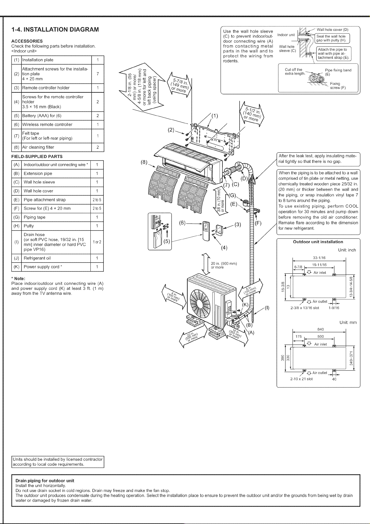
1-4.
INSTALLATION
DIAGRAM
ACCESSORIES
Check
the
following
parts
before
installation.
<[ndoor
unit>
(1)
[Installation
plate
4
Attachment
screws
for
the
installa-
(2)
|tion
plate
7
4*«
25mm
(3)
[Remote
controller
holder
1
Screws
for
the
remote
controller
(4)
|holder
2
3.5
x
16
mm
(Black)
(5)
{Battery
(AAA)
for
(6)
2
(6)
|Wireless
remote
controller
4
(7)
Felt
tape
1
(For
left
or
left-rear
piping)
(8)
[Air
cleaning
filter
2
FIELD-SUPPLIED
PARTS
(A)
|
Indoor/outdoor
unit
connecting
wire
*
4
(B)
|
Extension
pipe
4
(C)
|
Wall hole
sleeve
4
(D)
|
Wall hole
cover
4
(E)
|
Pipe
attachment
strap
2t05
(F)
|
Screw
for
(E)
4
x
20
mm
2t05
(G) |
Piping
tape
4
(H)
|
Putty
4
Drain
hose
(I)
(or
soft
PVC
hose,
19/32
in.
[15
tor?
mm]
inner
diameter
or
hard
PVC
pipe
VP16)
(J)
|
Refrigerant
oil
4
(K)
|
Power
supply
cord
*
4
*
Note:
Place
indoor/outdoor
unit
connecting
wire
(A)
and
power
supply
cord
(K)
at
least
3
ft.
(1
m)
away
from
the
TV
antenna
wire.
Units
should
be
installed
by
licensed
contractor
according
to
local
code
requirements.
2-1/8
in.
(55
mm)
or
more/
4-5/8
in.
(118
mm)
or
more
for
left
and
Use
the
wall
hole
sleeve
(C)
to
prevent
indoor/out-
door
connecting
wire
(A)
from
contacting
metal
parts
in
the
wall
and
to
protect
the
wiring
from
rodents.
indoor
unit
Seal
the
wail
hole
gap
with
putty
(R).
Wail
hole
sleeve
(C)
Attach
the
pipe
to
sca)
wall
with
pipe
at-
tachment
strap
(E).
Cut
off
the
Pipe
fixing
band
extra
length.
~~
(E)
Fixing
screw
(F)
left
back
piping
(using
spacer)
20
in.
(600
mm)
or
more
After
the
leak
test,
apply
insulating
mate-
rial
tightly
so
that
there
is
no
gap.
When
the
piping
is
to
be
attached
to
a
wall
comprised
of
tin
plate
or
metal
netting,
use
chemically
treated
wooden
piece
25/32
in.
(20
mm)
or
thicker
between
the
wall
and
the
piping,
or
wrap
insulation
vinyl
tape
7
to 8
turns
around
the
piping.
To
use
existing
piping,
perform
COOL
operation
for
30
minutes
and
pump
down
before
removing
the
old
air
conditioner.
Remake
flare
according
to
the
dimension
for
new
refrigerant.
Outdoor
unit
installation
Unit:
inch
33-1/16
19-11/16
6-7/8
be
aa
Air
infet
a
NAL
15-3/8
13
13-3/4~14-5/8
el
OD
Air
outlet
2-3/8
x
13/16
slot
1-9/16
Unit:
mm
390
330
nN
oD
2
D
=
oD
—+
Air
outlet
2-10
x
21
slot
40
Drain
piping
for
outdoor
unit
Install
the
unit
horizontally.
Do
not
use
drain
socket
in
cold
regions.
Drain
may
freeze
and
make
the fan
stop.
The
outdoor
unit
produces
condensate
during
the
heating
operation.
Select
the
installation
place
to
ensure
to
prevent
the
outdoor
unit
and/or
the
grounds
from
being
wet
by
drain
water
or
damaged
by
frozen
drain
water.
2.
INDOOR
UNIT
INSTALLATION
2-1.
ATTACHING
THE
INSTALLATION
PLATE
Y
Geis”
YY
tien.
(55mm)
or
more
Ceiling
2
4/8
in.
(55
mm)
or
more
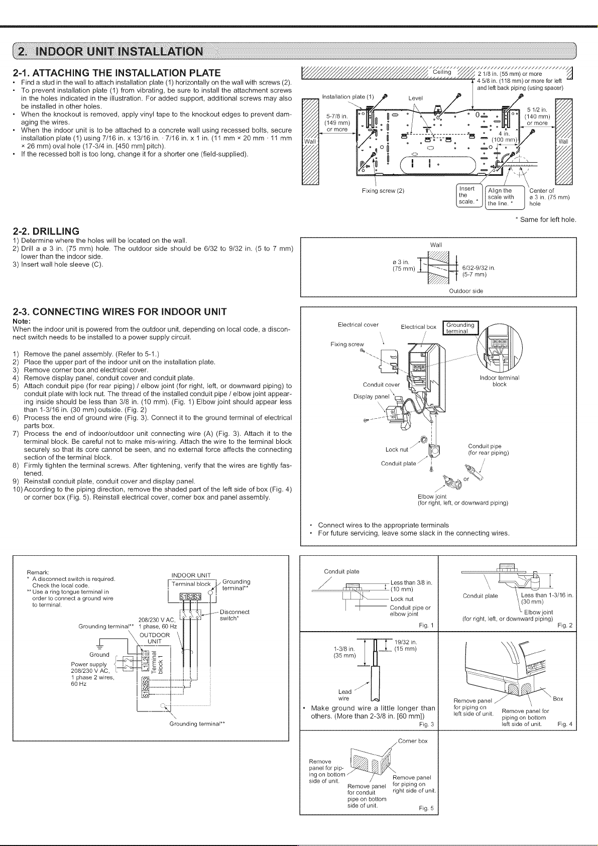
Find
a
stud
in
the
wall
to
attach
installation
plate
(1)
horizontally
on
the
wall
with
screws
(2).
4
oe
in
(ve
mm)
v7
more
for
oy
and
left
back
piping
(using
spacer
installation
plate
(
ZL.
~S
5
1/2
in.
5-7/8
in.
Ouse
©
[POF
(140
mm)
(149
mm)
°
ase.
a
or
more
or
more
*
To
prevent
installation
plate
(1)
from
vibrating,
be
sure
to
install
the
attachment
screws
in
the
holes
indicated
in
the
illustration.
For
added
support,
additional
screws
may
also
be
installed
in
other
holes.
«
When
the
knockout
is
removed,
apply
vinyl
tape
to
the
knockout
edges
to
prevent
dam-
aging
the
wires.
«
When
the
indoor
unit
is
to
be
attached
to
a
concrete
wall
using
recessed
bolts,
secure
installation
plate
(1)
using
7/16
in.
x
13/16
in.
-
7/16
in.
x
1
in.
(14
mm
x
20
mm
-
14
mm
art
3
3
ox
(100
mim)
x
26
mm)
oval
hole
(17-3/4
in.
[450
mm]
pitch).
eno
{>
*
If
the
recessed
bolt
is
too
long,
change
it
for
a
shorter
one
(field-supplied).
Fixing
screw
(2)
insert
Align
the
Center
of
the
,
||
scale
with
9 3 in.
(75mm)
scale.
the
line.
*
hole
*
Same
for
left
hole.
2-2.
DRILLING
1)
Determine
where
the
holes
will
be
located
on
the
wall.
Wall
2) Drill
a
@
3
in.
(75
mm)
hole.
The
outdoor
side
should
be
6/32
to
9/32
in.
(6
to
7
mm)
a
lower
than
the
indoor
side.
Zp
o3in.
Fp
“<4
3)
Insert
wall
hole
sleeve
(C).
(75
mr)
P=
632-9132
in.
(5-7
mm)
ZZ
Outdoor
side
2-3.
CONNECTING
WIRES
FOR
INDOOR
UNIT
Note:
When
the
indoor
unit
is
powered
from
the
outdoor
unit,
depending
on
local
code,
a
discon-
nect
switch
needs
to
be
installed
to
a
power
supply
circuit.
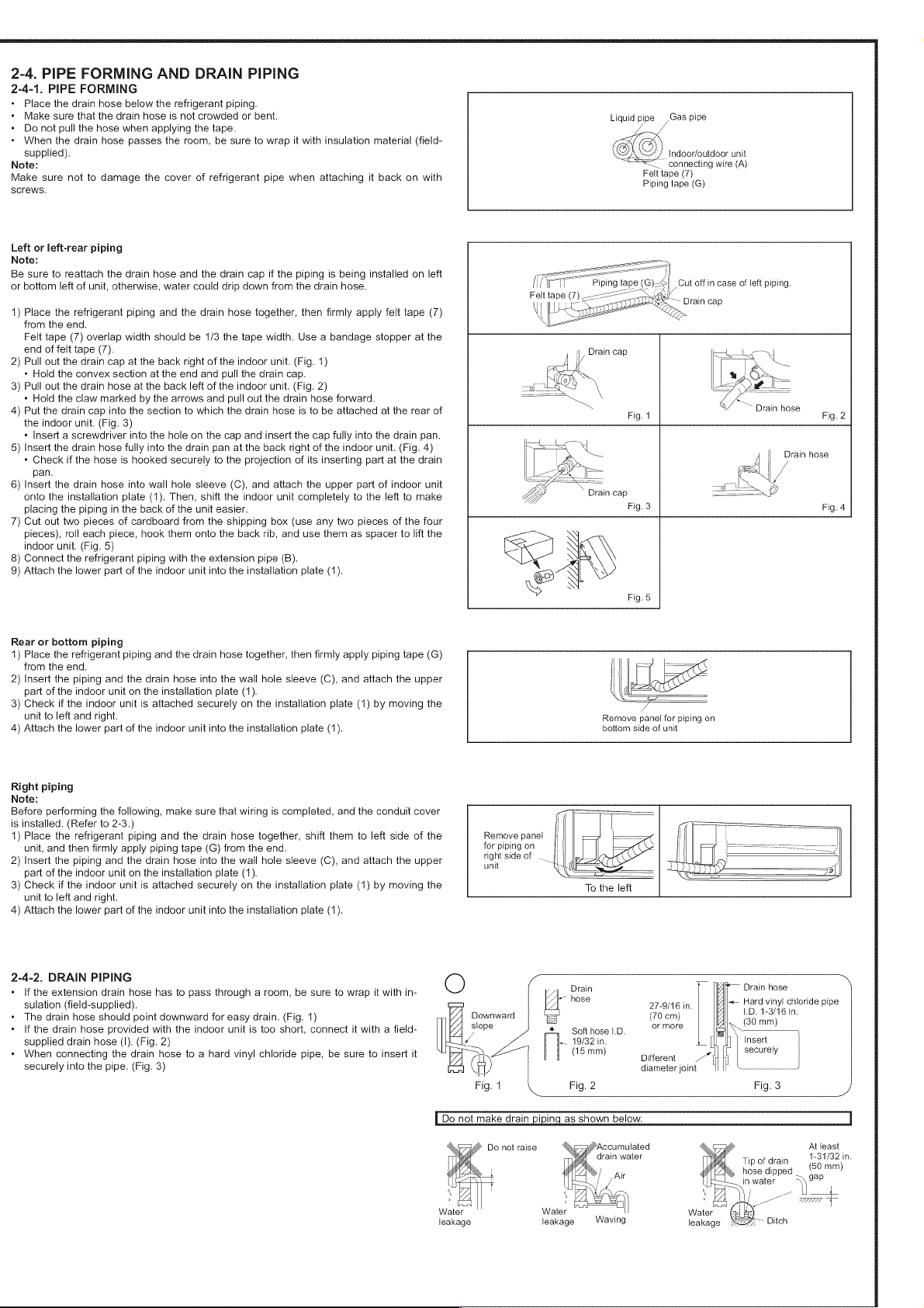
Grounding
terminal
Electrical
cover
Electrical
box
Fixing
screw
s
1)
Remove
the
panel
assembly.
(Refer
to
5-1.)
ae
aT
2)
Place
the
upper
part
of
the
indoor
unit
on
the
installation
plate.
S|
—
3)
Remove
corner
box
and
electrical
cover.
Ce
4)
Remove
display
panel,
conduit
cover
and
conduit
plate.
indoor
terminal
5)
Attach
conduit
pipe
(for
rear
piping)
/
elbow
joint
(for
right,
left,
or
downward
piping)
to
Conduit
cover
block
conduit
plate
with lock
nut.
The
thread
of
the
installed
conduit
pipe
/
elbow
joint
appear-
Display
panel
ing
inside
should
be
less
than
3/8
in.
(10
mm).
(Fig.
1)
Elbow
joint
should
appear
less
than
1-3/16
in.
(30
mm)
outside.
(Fig.
2)
6)
Process
the
end
of
ground
wire
(Fig.
3).
Connect
it
to
the
ground
terminal
of
electrical
geo
parts
box.
|
7)
Process
the
end
of
indoor/outdoor
unit
connecting
wire
(A)
(Fig.
3).
Attach
it
to
the
i
terminal
block.
Be
careful
not
to
make
mis-wiring.
Attach
the
wire
to
the
terminal
block
U®
Conduit
pi
securely
so
that
its
core
cannot
be
seen,
and
no
external
force
affects
the
connecting
Lock
nut
fo
(for
rear
piping)
section
of
the
terminal
block.
;
a
/
8)
Firmly
tighten
the
terminal
screws.
After
tightening,
verify
that
the
wires
are
tightly
fas-
Conduit
plate
A
/
tened.
f
9)
Reinstall
conduit
plate,
conduit cover and
display
panel.
RV
or
10)
According
to
the
piping
direction,
remove
the
shaded
part
of
the
left
side
of
box
(Fig.
4)
x
or
corner
box
(Fig.
5).
Reinstall
electrical
cover,
corner
box
and
panel
assembly.
Elbow
joint
(for
right,
left,
or
downward
piping)
*
Connect
wires
to
the
appropriate
terminals
«
For
future
servicing,
leave
some
slack
in
the
connecting
wires.
sei
econnect
switch
is
required
INDOOR
UNIT
:
cons
pate
Check
the
local
code.
:
Terminal
block
|
Brounding
(io,
me
38
in.
saad
*
Use
a
ring
tongue
terminal
in
mm
;
=
,
order
to
connect
a
ground
wire
t Lock
nut
Conduit
plate
Gomme
1-3/16
in.
to
terminal.
hi
L,
:
Conduit
pipe
or
i
Lt
Disconnect
elbow
joint
Elbow
joint
208/230
VAC,
*
J
switch*
(for
right,
left,
or
downward
piping)
Grounding
terminal**
4
phase,
60
Hz
Fig.
1
Fig.
2
OUTDOOR
UNIT
[
19/32
in.
=
“oe
IY
1-3/8
in.
(15
mm)
Ground
.
SL
|
(35
mm)
os
a
Power
supply
<_
is
ES
|
208/230
V
AC,
(R=
2s
:
1
phase
2
wires,
h
60
Hz
:
eB
Lead
<
”
.
:
wire
Remove
panel
Box
a
«
Make
ground
wire
a
little
longer
than
forpipingon
a
move
panel
for
others.
(More
than
2-3/8
in.
[60
mm)
left
side
of
unit,
ing
on
bottom
Grounding
terminal**
Fig.
3
left
side
of
unit.
Fig.
4
Corner
box
Remove
panel
for
pip-
ing
on
boltom
Remove
panel
side
of
unit.
a
Remove
panel
for
piping
on
for
conduit
right
side
of
unit.
pipe
on
bottom
side
of
unit.
Fig.
5
2-4,
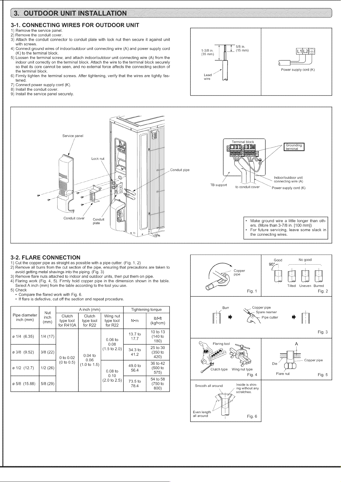
PIPE
FORMING
AND
DRAIN
PIPING
2-4-1.
PIPE
FORMING
«
Place
the
drain
hose
below
the
refrigerant
piping.
*
Make
sure
that
the
drain
hose
is
not
crowded
or
bent.
«
Do
not
pull
the
hose
when
applying
the
tape.
«
When
the
drain
hose
passes
the
room,
be
sure
to
wrap
it
with
insulation
material
(field-
supplied).
Note:
Make
sure
not
to
damage
the
cover
of
refrigerant
pipe
when
attaching
it
back
on with
screws.
Left
or
left-rear
piping
Note:
Be
sure
to
reattach
the
drain
hose
and
the
drain
cap
if
the
piping
is
being
installed
on
left
or
bottom
left
of
unit,
otherwise,
water
could
drip
down
from
the
drain
hose.
1)
Place
the
refrigerant
piping
and
the
drain
hose
together,
then
firmly
apply
felt
tape
(7)
from
the
end.
Felt
tape
(7)
overlap
width
should
be
1/3
the
tape
width.
Use
a
bandage
stopper
at
the
end
of
felt
tape
(7).
2)
Pull
out the
drain
cap
at
the
back
right
of
the
indoor
unit.
(Fig.
1)
*
Hold
the
convex
section
at
the
end and
pull
the
drain
cap.
3)
Pull
out the
drain
hose
at
the
back
left
of
the
indoor
unit.
(Fig.
2)
*
Hold
the
claw
marked
by
the
arrows
and
pull
out the
drain
hose
forward.
4)
Put
the
drain
cap
into
the
section
to
which
the
drain
hose
is
to
be
attached
at
the
rear
of
the
indoor
unit.
(Fig.
3)
*
Insert
a
screwdriver
into
the
hole
on
the
cap
and
insert
the
cap
fully
into
the
drain
pan.
5)
Insert
the
drain
hose
fully
into
the
drain
pan
at
the
back
right
of
the
indoor
unit.
(Fig.
4)
*
Check
if
the
hose
is
hooked
securely
to
the
projection
of
its
inserting
part
at
the
drain
pan.
6)
Insert
the
drain
hose
into
wall
hole
sleeve
(C),
and
attach
the
upper
part
of
indoor
unit
onto
the
installation
plate
(1).
Then,
shift
the
indoor
unit
completely
to
the
left
to
make
placing
the
piping
in
the
back
of
the
unit
easier.
7)
Cut
out
two
pieces
of
cardboard
from
the
shipping
box
(use
any
two
pieces
of
the
four
pieces),
roll
each
piece,
hook
them
onto
the
back
rib,
and
use
them
as
spacer
to
lift
the
indoor
unit.
(Fig.
5)
8)
Connect
the
refrigerant
piping
with
the
extension
pipe
(B).
9)
Attach
the
lower
part
of
the
indoor
unit
into
the
installation
plate
(1).
Rear
or
bottom
piping
1)
Place
the
refrigerant
piping
and
the
drain
hose
together,
then
firmly
apply
piping
tape
(G)
from
the
end.
2)
Insert
the
piping
and
the
drain
hose
into
the
wall
hole
sleeve
(C),
and
attach
the
upper
part
of
the
indoor
unit
on
the
installation
plate
(1).
3)
Check
if
the
indoor
unit
is
attached securely
on
the
installation
plate
(1)
by
moving
the
unit
to
left
and
right.
4)
Attach
the
lower
part
of
the
indoor
unit
into
the
installation
plate
(1).
Right
piping
Note:
Before
performing
the
following,
make
sure
that
wiring
is
completed,
and
the
conduit
cover
is
installed.
(Refer
to
2-3.)
1)
Place
the
refrigerant
piping
and
the
drain
hose
together,
shift
them
to
left
side
of
the
unit,
and
then
firmly
apply
piping
tape
(G)
from
the
end.
2)
Insert
the
piping
and
the
drain
hose
into
the
wall
hole
sleeve
(C),
and
attach
the
upper
part
of
the
indoor
unit
on
the
installation
plate
(1).
3)
Check
if
the
indoor
unit
is
attached securely
on
the
installation
plate
(1)
by
moving
the
unit
to
left
and
right.
4)
Attach
the
lower
part
of
the
indoor
unit
into
the
installation
plate
(1).
2-4-2.
DRAIN
PIPING
Liquid
pipe
_,
Gas
pipe
Indoor/outdoor
unit
=<
connecting
wire
(A)
Felt
tape
(7)
Piping
tape
(G)
|
Cut
offin
case
of
left
piping.
/
“~
Drain
hose
;
Fig.
1
Fig.
2
Drain
hose
Drain
cap
Fig.
3
Fig.
4
Fig.
5
Remove
pane!
for
piping
on
bottom
side
of
unit
Remove
panel
for
piping
on
right
side
of
unit
To
the
left
Z
*
[If
the
extension
drain
hose
has
to
pass
through
a
room,
be
sure
to
wrap
it
with
in-
-
pain
Drain
hose
a
sulation
(field-supplied).
27-9/16
in.
a
nara
vinyl
chioride
pipe
«
The
drain
hose
should
point
downward
for
easy
drain.
(Fig.
1)
Downward
S
(70
cm)
G0
mm)
n
+
If
the
drain
hose
provided
with
the
indoor
unit
is
too
short,
connect
it
with
a
field-
slope
*
Soft
hose
LD.
or
more
supplied
drain
hose
(1).
(Fig.
2)
=
i
|
He.
19/32
in.
L
insert
«
When
connecting
the
drain
hose
to
a
hard
vinyl
chloride
pipe,
be
sure
to
insert
it
=]
| |
@Smm)
Different
=”
securely
securely
into
the
pipe.
(Fig.
3)
@®
diameter
joint
1)
IP
een
Fig.
4
Fig.
2
Fig.
3
|
Do
not
make
drain
piping
as
shown
below.
I
Do
not
raise
ccumulated
At
least
drain
water
“ :
1-31/32
in.
Tip
of
drain
hose
dipped
(50
mm)
Water
leakage
Wa
leakage
in
water
*s
ter
Water
leakage
3.
OUTDOOR
UNIT
INSTALLATION
3-1.
CONNECTING
WIRES
FOR
OUTDOOR
UNIT
1)
Remove
the
service
panel.
2)
Remove
the
conduit
cover.
3)
Attach
the
conduit
connector
to
conduit
plate
with
lock
nut
then
secure
it
against
unit
with
screws.
5/8
i
4)
Connect
ground
wires
of
indoor/outdoor
unit
connecting
wire
(A)
and
power
supply
cord
4-3/8
in
|
(15
mm)
(K)
to
the
terminal
block.
(35
mm)
5)
Loosen
the
terminal
screw,
and
attach
indoor/outdoor
unit
connecting
wire
(A)
from
the
indoor
unit
correctly
on
the
terminal
block.
Attach
the
wire
to
the
terminal
block
securely
so
that
its
core
cannot
be
seen,
and
no
external
force
affects
the
connecting
section
of
the
terminal
block.
a
Power
supply
cord
(K)
6)
Firmly
tighten
the
terminal
screws.
After
tightening,
verify
that
the
wires
are
tightly
fas-
Lead
tened.
wire
7)
Connect
power
supply
cord
(kK).
8)
Install
the
conduit
cover.
9)
Install
the
service
panel
securely.
ee
ee
Se
il
Service
panel
|
a
Terminal
block
a
="
=
FOUNCING
iL
iS
terminal
Lock
nut
Conduit
pipe
Indoor/outdoor
unit
Jot
connecting
wire
(A)
7B
support
to
conduit
cover
Power
supply
cord
(K)
Conduit
cover
Conduit
plate
«
Make
ground
wire
a
little
longer
than
oth-
ers.
(More
than
3-7/8
in.
[100
mm])
For
future
servicing,
leave
some
slack
in
the
connecting
wires.
3-2.
FLARE
CONNECTION
ood
No
good
1)
Cut
the
copper
pipe
as
straight
as
possible
with
a
pipe
cutter.
(Fig.
1,
2)
90°
pov
Lenn
~
2)
Remove
all
burrs
from
the
cut
section
of
the
pipe,
ensuring
that
precautions
are
taken
to
/
|
avoid
getting
metal
shavings
into
the
piping.
(Fig.
3)
a
Copper
~
3)
Remove
flare
nuts
attached
to
indoor
and
outdoor
units,
then
put
them
on
pipe.
pip
4)
Flaring
work
(Fig.
4, 5).
Firmly
hold
copper
pipe
in
the
dimension
shown
in
the
table.
i i i
Select
A
inch
(mm)
from
the
table
according
to
the
tool
you
use.
Tilted
Uneven
Burred
5)
Check
Fig.
4
Fig.
2
«
Compare
the
flared
work
with
Fig.
6.
g 9
«
If
flare
is
defective,
cut
off
the
section
and
repeat
procedure.
° A .
Burr
Copper
pipe
Nut
Ainch
(mm)
Tightening
torque
Z
Spare
reamer
Pipe
diameter
|
joy
Clutch
Clutch
|
Wing
nut
Ibfeft
;
>
EO
Pipe
cutter
»
;
inch
(mm)
type
tool
|
type
tool
|
type
tool
Nem
(mm)
(kgf*cm)
| |
for
R410A
|
for
R22
for
R22
10
to
13
Fig.
3
@1/4
(6.35)
|
1/4
(17)
13.7
to
(140
to
0.06
to
17.7
180)
fee
25
to
30
;
1.5
to
2.0
o
23/8
(9.52)
|
3/8
(22)
(
}}
343t0
|
“356
to
0.04
to
41.2
420
0
to
0.02
)
;
0.06
.—--—
Copper
pipe
(0
to
0.5)
(1.0
to
1.5)
49.0
to
36
to
42
Die
@
1/2
(12.7)
1/2
(26)
0.08
to
56.4
O75).
-
Clutch
type
Wing
nut
type
0.10
Fig.
4
Flare
nut
Fig.
5
(2.010
2.5)
73.5to
|
54
'058
@
5/8
(15.88)
|
5/8
(29)
78.4
S00)”
Smooth
all
around
ing
without
any
scratches.
Even
length
all
around
Fig.
6
3-3.
PIPE
CONNECTION
«
Fasten
flare
nut
with
a
torque
wrench
as
specified
in
the
table
above.
«
When
fastened
too
tight,
flare
nut
may
eventually
break
and
cause
refrigerant
leakage.
Indoor
unit
connection
Connect
both
liquid
and
gas
piping
to
indoor
unit.
«
Apply
a
thin
coat
of
refrigerant
oil
(J)
on
the
seat
surface
of
pipe.
*
Toconnect,
first
align
the
center,
then
tighten
the
first
3
to
4
turns
of
flare
nut.
*
Use
tightening
torque
table
in
(3-2.)
as
a
guideline
for
indoor
unit
side
joints,
and
tighten
using
two
wrenches.
Excessive
tightening
damages
the
flare
section.
Outdoor
unit
connection
Connect
pipes
to
stop
valve
pipe
joint
of
the
outdoor
unit
following
the
same
procedure
detailed
in
Indoor
unit
connection.
*
For
tightening,
use
a
torque
wrench
or
spanner.
A
WARNING
When
installing
the
unit,
securely
connect
the
refrigerant pipes
before
starting
the
compressor.
3-4.
INSULATION
AND
TAPING
1)
Cover
piping
joints
with
pipe
cover.
2)
For
outdoor
unit
side,
insulate
the
piping,
including
valves.
3)
Apply
piping
tape
(G)
starting
from
the
connection
on
the
outdoor
unit.
«
When
piping
has
to
be
installed
through
a
ceiling,
closet
or
where
the
temperature
and
humidity
are
high,
use
additional
field-supplied
insulation
to
prevent
condensation.
4.
PURGING
PROCEDURES,
LEAK
TEST,
AND
TEST
RUN
4-1.
PURGING
PROCEDURES
AND
LEAK
TEST
1)
Remove
service
port
cap
of
stop
valve
on
the
side
of
the
outdoor
unit
gas
pipe.
(The
stop
valves
are
fully
closed
and
covered
in
caps
in
initial
state.)
2)
Connect
gauge
manifold
valve
and
vacuum
pump
to
service
port
of
stop
valve
on
the
gas
pipe
side
of
the
outdoor
unit.
3)
Run
the
vacuum
pump
15
minutes
or
more.
4)
Check
the
vacuum
with
the
gauge
manifold
valve,
then
close
it
and
shut
off
the
vacuum
pump.
5)
Leave
as
it
is
for
one
or
two
minutes.
Make
sure
pointer
gauge
manifold
valve
remains
in
the
same
position.
Confirm
that
pressure
gauge shows
—0.101
MPa
[Gauge]
(-30
in.Hg
[-760
mmHg]J).
6)
Quickly
remove
gauge
manifold
valve
from
service
port
of
stop
valve.
7)
After
refrigerant pipes
are
connected
and
evacuated,
fully
open
all
stop
valves
on
both
sides
of
gas
pipe
and
liquid
pipe.
Operating
the
unit
without
fully
opening
the
valves
lowers
the
performance
and
causes
problems.
8)
Refer
to
1-3.
SPECIFICATIONS,
and
charge
the
prescribed
amount
of
refrigerant
if
needed.
Be
sure
to
charge
slowly
with
liquid
refrigerant.
Otherwise,
composition
of
the
refrigerant
in
the
system
may
be
changed
and
affect
performance
of
the
air
conditioner.
9)
Tighten
cap
of
service
port.
10)
Conduct
a
leak
test
4-2.
TEST
RUN
1)
Insert
power
supply
plug
into
the
power
outlet
and/or
turn
on
the
breaker.
2)
Press
the
E.O.
SW
once.
Test
run
will
be
performed
for
30
minutes.
If
the
left
operation
indicator
light
blinks
every
0.5
seconds,
inspect
the
indoor/outdoor
unit
connecting
wire
(A).
After
the
test
run,
emergency
COOL
mode
(75°F
[24°C]
COOL)
willstart
3)
To
stop
operation,
press
the
E.O.
SW
several
times
until
all
LED
lamps
turn
off.
Refer
to
operating
instructions
for
de-
tails.
Emergency
operation
switch
. . . .
(E.0.
SW)
Checking
the
remote
(infrared)
signal
reception
Press
the
ON/OFF
button
on
the
remote
controller
and
listen
for
an
audible
indicator
from
the
indoor
unit.
Press
the
ON/OFF
button
again
to
turn
the
air
conditioner
off.
*
Once
the
compressor
stops,
the
restart
preventive
device
operates
so
the
compressor
will
not
operate
for
3
minutes
to
protect
the
air
conditioner.
4-3.
AUTO
RESTART
FUNCTION
This
product
is
equipped
with
an
auto
restart
function.
When
the
power
supply
is
cut
off
during
operation,
such
as
during
blackouts,
the
function
automatically
starts
operation
in
the
previous
setting
once
the
power
supply
is
resumed.
(Refer
to
the
operating
instructions
for
details.)
0.101
MPa
Compound
pressure
gauge
*4
to 5
turns
Frorque 106
to
(-30
inHg
(for
R410A)
.
29.4
Nem,
15
to
[-760
mmHg)
Pressure
gauge
Close
22
tbfefl
[200
to
Stop
valve
(for
R410A)
for
LIQUID
Gauge
manifold
valve
(for
R410A)
*Open
‘|
300
kgf*cm])
Handle
High
Hexagonal
wrench
pe
Charge
hose
(for
R410A)
Service
port
cap
(Torque
13.7
to
17.7
Nem,
10
to
13
Ibfeft
[140
to
180
kgfecm])
Adapter
for
pre-
MENTE
venting
the
back
flow
Vacuum
pump
(or
the
vacuum
pump
with
the
function
to
prevent
the
back
flow)
[Precautions
when
using
the
control
valve]
When
attaching
the
control
valve
to
the
service
port.
valve core
ma
deform
or
loosen
if
excess
pressure
is.applied.
This
may
cause
gas
leak,
g
4
When
attaching
the
control
valve
to
/
Service
port
the
service
port,
make
sure
that
the
Controt
vane
valve
core
is
in
closed
position,
and
Onen’®
oo
then tighten
part
A.
Do
not
tighten
pen
part
A
or
turn
the
body
when
valve
Close
Charge
hose
vo
igs
Body
core
is
in
open
position.
Caution:
«
After
test
run
or
remote
signal
reception
check,
turn
off
the
unit
with
the
E.O.
SW
or
the
remote
controller
before
turning
off
the
power
supply.
If
this
procedure
is
not
performed,
the
unit
will
automatically
begin
operation
when
power
supply
is
resumed.
To
the
user
*
After
installing
the
unit,
explain
to
the
user
about
auto
restart
function.
«
[f
auto
restart
function
is
unnecessary,
it
can
be
deactivated.
Consult
the
service
representative
to
deactivate
the
function.
Refer
to
the
service
manual
for
details.
4-4.
EXPLANATION
TO
THE
USER
«
Using
the
OPERATING
INSTRUCTIONS,
explain
to
the
user
how
to
use
the
air
conditioner
(the
remote
controller,
removing
the
air
filters,
placing
or
removing
the
re-
mote
controller
from
the
remote
controller
holder,
cleaning
methods,
precautions
for
operation,
etc.)
«
Recommend
that
the
user read
the
OPERATING
INSTRUCTIONS
carefully.
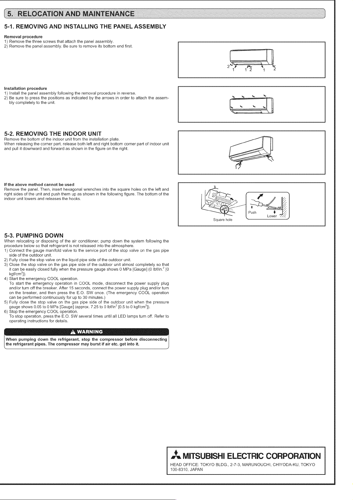
5.
RELOCATION
AND
MAINTENANCE
5-1.
REMOVING
AND
INSTALLING
THE
PANEL
ASSEMBLY
Removal
procedure
1)
Remove
the
three
screws
that
attach
the
panel
assembly.
2)
Remove
the
panel
assembly.
Be
sure
to
remove
its
bottom
end
first.
Installation
procedure
1)
Install
the
panel
assembly
following
the
removal
procedure
in
reverse.
2)
Be
sure
to
press
the
positions
as
indicated
by
the
arrows
in
order
to
attach
the
assem-
a = =
bly
completely
to
the
unit.
fw
x
*
——_
5-2.
REMOVING
THE
INDOOR
UNIT
Remove
the
bottom
of
the
indoor
unit
from
the
installation
plate.
When
releasing
the
corner
part,
release
both
left
and
right
bottom
corner
part
of
indoor
unit
and
pull
it
downward
and
forward
as
shown
in
the
figure
on
the
right.
if
the
above
method
cannot
be
used
Remove
the
panel.
Then,
insert
hexagonal
wrenches
into
the
square
holes
on
the
left
and
right
sides
of
the
unit
and
push
them
up
as
shown
in
the
following
figure.
The
bottom
of
the
indoor
unit
lowers
and
releases
the
hooks.
Square
hole
5-3.
PUMPING
DOWN
When
relocating
or
disposing
of
the
air
conditioner,
pump
down
the
system
following
the
procedure
below
so
that
refrigerant
is
not
released
into
the
atmosphere.
1)
Connect
the
gauge
manifold
valve
to
the
service
port
of
the
stop
valve
on
the
gas
pipe
side
of
the
outdoor
unit.
2)
Fully
close
the
stop
valve
on
the
liquid
pipe
side
of
the
outdoor
unit.
3)
Close
the
stop
valve
on
the
gas
pipe side
of
the
outdoor
unit
almost
completely
so
that
it
can
be
easily
closed
fully
when
the
pressure
gauge
shows
0
MPa
[Gauge]
(0
Ibffin.”
[0
kgficm’]).
4)
Start
the
emergency
COOL
operation.
To
start
the
emergency
operation
in
COOL
mode,
disconnect
the
power
supply
plug
and/or
turn
off
the
breaker.
After
15
seconds,
connect
the
power
supply
plug
and/or
turn
on
the
breaker,
and
then
press
the
E.O.
SW
once.
(The
emergency
COOL
operation
can
be
performed
continuously
for
up
to
30
minutes.)
5)
Fully
close
the
stop
valve
on
the
gas
pipe side
of
the
outdoor
unit
when
the
pressure
gauge
shows
0.05
to
0
MPa
[Gauge]
(approx.
7.25
to
0
Ibffin’
[0.5
to
0
kgf/cm’).
6)
Stop
the
emergency
COOL
operation.
To
stop
operation,
press
the
E.O.
SW
several
times
until
all
LED
lamps
turn
off.
Refer
to
operating
instructions
for
details.
A
WARNING
When
pumping
down
the
refrigerant,
stop
the
compressor
before
disconnecting
the
refrigerant
pipes.
The
compressor
may
burst
if
air
etc.
get
into
it.
aa
MITSUBISHI
ELECTRIC
CORPORATION
HEAD
OFFICE:
TOKYO
BLDG.,,
2-7-3,
MARUNOUCHI,
CHIYODA-KU,
TOKYO
100-8310,
JAPAN