Loading ...
Loading ...
Loading ...
6
INSTALLATION INSTRUCTIONS
WALL THERMOSTAT TERMINAL
Note: Using a wall thermostat is optional.
Important: Only trained, qualifi ed personnel
should access the electrical panel on the appliance
and install electrical accessories. Contact a local
electrical contractor, dealer or distributor for
assistance.
Thermostat Wire Routing
Thermostat wire is fi eld supplied. Recommended
wire gauge is 18 to 20 gauge solid thermostat wire.
Note: It is recommended that extra wires are run
to the appliance in case any are damaged during
installation. Thermostat wire should always be
routed around or under, never through the wall
sleeve. The wire should be routed behind the front
panel to the easily accessible terminal connector.
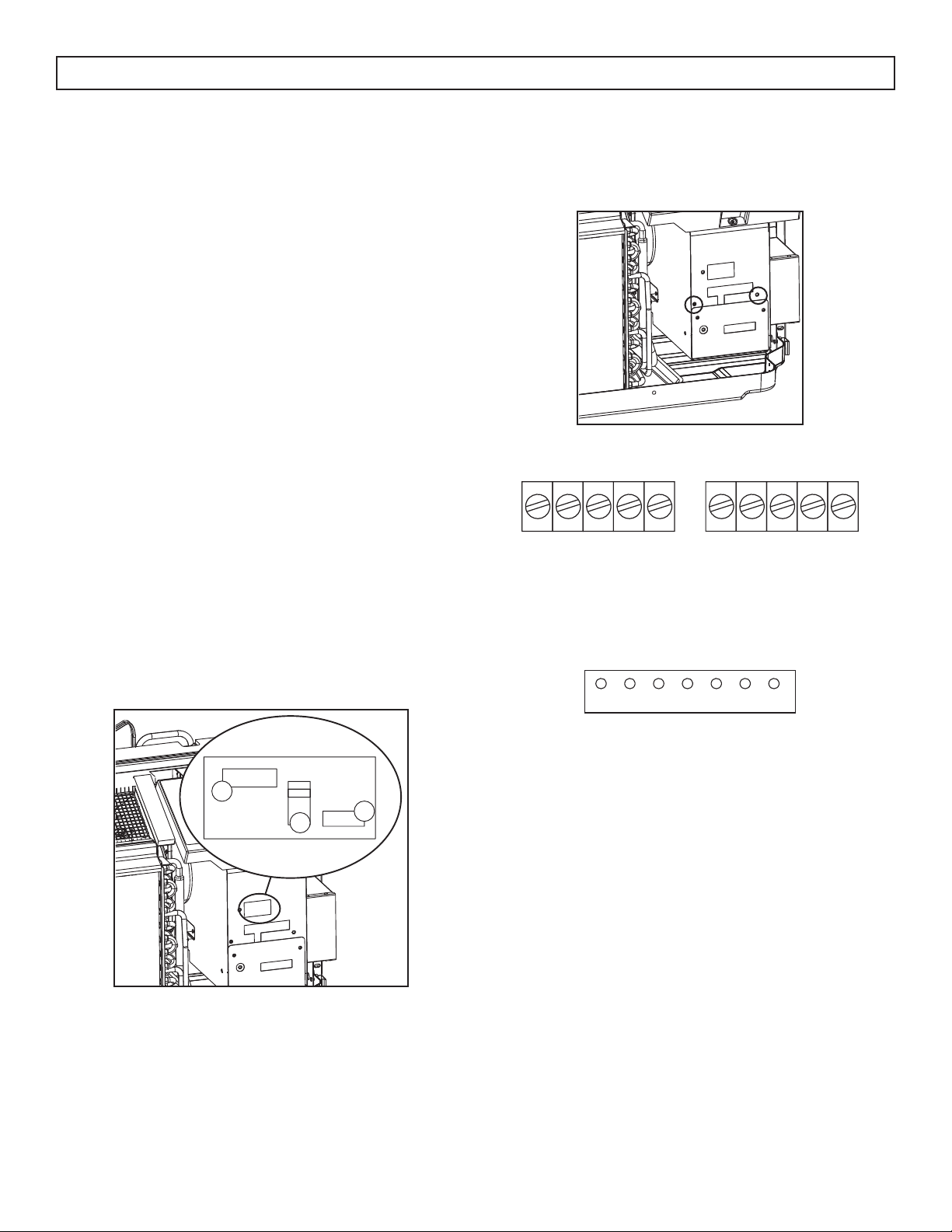
Pull the dip switch to the DOWN(OFF) position.
Insert the wire connector of the wall thermostat
into the relevant terminal according to the different
shapes as shown.
A: Dip switch
B: Terminal
A
B
B
PTAC Other Wall Thermostat
Remove the two screws as shown and take the cover
panel down.
Terminal of PTAC other wall thermostat (MODE A)
FC(L)
FC(N)
LOW-FAN
HI-FAN
4-WAY
HEAT2
HEAT1
COMP
24V(N)
24V(L)
Terminal of PTAC other wall thermostat (MODE B)
LOW-FAN
HI-FAN
4-WAY
HEAT1
COMP
24V(L)
24V(N)
Caution: Failure to follow this caution may result
in equipment damage or improper operation.
Improper wiring may damage the electronics.
Common busing is not permitted. Damage or erratic
operation may result.
Loading ...
Loading ...
Loading ...