Loading ...
Loading ...
Loading ...
INSTALLATION INSTRUCTIONS
4
DIP SWITCHES
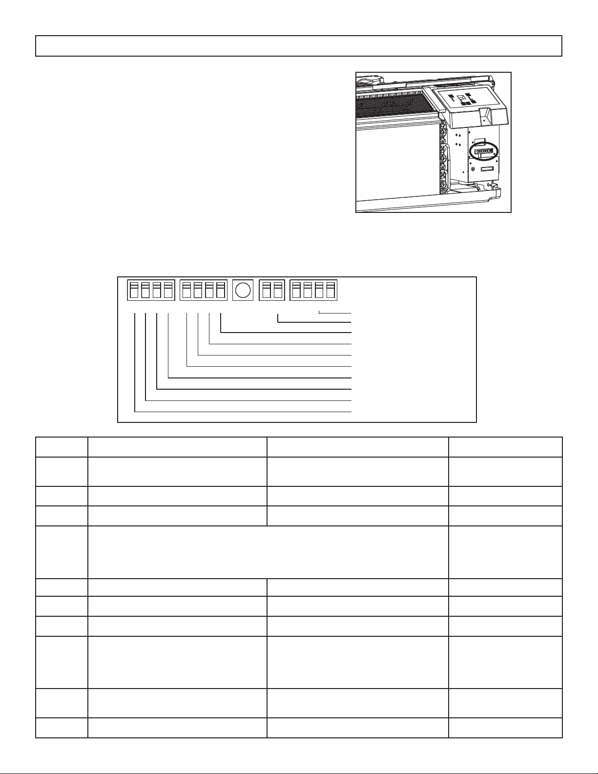
Dip switch controls are located behind the front
panel through an opening below the control panel.
Remove the front panel to access the dip switches.
Dip switches are accessible without opening the
control box.
The appliance should be unplugged before making
adjustments to the dip switches.
DIP SWITCH CONFIGURATIONS
See the table below for dip switch confi gurations and functions.
UP(ON)
DOWN(OFF)
1 2 3 4 1 2 3 4
S
1
S2
S
3
S
4
S5
S6
S7
S8
X
S
9
A0-
A3
1 2 1 2 3 4
S11
Wall thermostat type
Load delay for 3 seconds
Heating type
Temperature display type
Control type
Setpoint limit 1
Setpoint limit 2
Fan CON/CYC for heating
Fan CON/CYC for cooling
Low temp. Protection
Number UP (ON) DOWN (OFF) Remarks
S1 Electric heat only Electric and pump heat Heat pump model
only
S2 Temperature display °F Temperature display °C
S3 Wall thermostat enable Control panel enable
S4*S5 UP*UP: 61°F ~ 86°F (16°C ~ 30°C)
UP*DOWN: 65°F ~ 78°F (18°C ~ 26°C)
DOWN*UP: 63°F ~ 80°F (17°C ~ 27°C)
DOWN*DOWN: 68°F ~ 75°F (20°C ~ 24°C)
Confi guration of S4
and S5 combine to
select set point range
S6 Fan continuous run for heating Fan cycle for heating
S7 Fan continuous run for cooling Fan cycle for cooling
S8 Low temperature protection enable Low temperature protection disable
S9 (S3
UP)
Use some types of wall thermostat Use PTAC other wall thermostat Consult with
sales agent or
manufacturer for
details
S9 (S3
DOWN)
Use control panel only Use control panel or some types of
wall thermostat
Sw11 Load delay for 3 seconds Normal Optional
Loading ...
Loading ...
Loading ...