Loading ...
Loading ...
Loading ...
3. Provide an Adequate Gas Supply
The cooktop covered in these installation instructions is
designed to operate on natural gas at 4" (10.2 cm) of
manifold pressure or on LP gas at 10" (25.4 cm) of
manifold pressure.
A convertible pressure regulator is supplied with each
surface unit and MUST BECONNECTED IN SERIES
between the supply line and the valve manifold
regardless of which type of gas is being used.
The convertible regulator for the surface units must be
located and turned in such manner to allow for easy
access to the convertible feature.
For proper operation, the maximum inlet pressure to
the regulator must not exceed 14"' (35.6 cm) of water
column (W.C.) pressure for both LPand Natural Gas.
For checking the regulator, the inlet pressure must be at
least 1" (2.5 cm) (or 2.5 kPa) greater than the regulator
manifold pressure setting. If the regulator isset for 4"
(10.2 cm) of manifold pressure, the inlet pressure must
be at least 5"(12.7 cm). If the regulator is set for 10"
(25.4 cm), the inlet pressure must be at least 11" (27.9
cm),
Tile gas supply line to the cooktops should be Y2" (!.3
cm) or 3A" (1.9 cm) pipe.
4. Connection to gas
IMPORTANT: Remove all packing material and literature
from cooktop before connecting gas and electrical supply
to the appliance.
Seal all openings in the wall behind the cooktop and in
the floor under the cooktop after gas supply line is
installed.
Install Pressure Regulator
Install the pressure regulator with the arrow on tile
regulator pointing up toward the unit in a position where
you can reach the access cap.
Do not make tile connection too tight.
The regulator is die cast. Overtightening may (:rack the
regulator resulting in a gas leak and possible fire or
explosion.
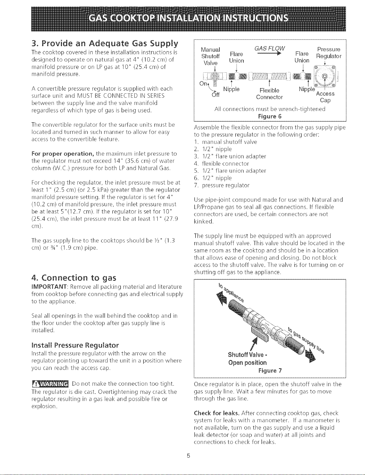
ManuaH GAS FLOW Pressu re
Shutoff Hare _€_ Hare ReguHator
Valve Union Union
On_ Nipplet r i t
Flexible Nuppe Access
Off Connector
Cap
All connections must be wrench4ightened
Figure 6
Assemble the flexible connector from the gas supply pipe
to the pressure regulator in the following order:
1. manual shutoff valve
2. 1/2" nipple
3. 1/2" flare union adapter
4. flexible connector
5. 1/2" flare union adapter
6. 1/2" nipple
7. pressure regulator
Use pipe-ioint compound made for use with Natural and
LP/Propane gas to seal all gas connections. If flexible
connectors are used, be certain connectors are not
kinked.
The supply line must be equipped with an approved
manual shutoff valve. This valve should be located in the
same room as the cooktop and should be in a location
that allows ease of opening and (:losing. Do not block
access to the shutoff valve. The valve is for turning on or
shutting off gas to the appliance.
Open position
Figure 7
Once regulator is in place, open the shutoff valve in the
gas supply line. Wait a few minutes for gas to move
through tile gas line.
Check for teaks_ After connecting cooktop gas, check
system for leaks with a manometer. If a manometer is
not available, turn on the gas supply and use a liquid
leak detector (or soap and water) at all joints and
connections to check for leaks.
Loading ...
Loading ...
Loading ...