This water heater should be installed in accordance with the local code authority having jurisdiction, the power company or electric utility, and this installation manual. In the absence of local code requirements, follow the regulations set forth in the latest edition of the National Electric Code, NFPA70. This is available from the following: National Fire Protection Agency 1 Batterymarch Park Quincy, MA 02269 American National Standards Institute 1430 Broadway New York, NY 10018 Check your phone listings for the local authorities having jurisdiction over your installation.
Consumer Responsibilities
This manual has been prepared to acquaint you with the installation, operation, and maintenance of your electric water heater and provide important safety information in these areas. We urge you to read all of the instructions thoroughly before attempting the installation or operation of this water heater. This manual should be kept for future reference. The manufacturer of this water heater will not be liable for any damages caused by failure to comply with the installation and operating instructions outlined in this manual. If you lack the necessary skills required to properly install this water heater or you have difficulty following the directions, you should not proceed but have a qualified person perform the installation of this water heater. Examples of a qualified personnel include: licensed plumbers, authorized electric company personnel, and authorized service person. Massachusetts code requires this water heater to be installed in accordance with Massachusetts Plumbing and Fuel Code 248-CMR 2.00: State Plumbing Code and 248-CMR 5.00. A data plate identifying your water heater can be found adjacent to the energy smart module. When referring to your water heater always have the information listed on the data plate readily available, to include the model and serial number. Retain your original receipt as proof of purchase.
Insulation Blankets
The use of an insulation blanket on this water heater is not needed nor recommended. The purpose of an insulation blanket is to reduce the standby heat loss encountered with storage tank heaters. Your water heater meets or exceeds the National Appliance Energy Conservation Act standards with respect to insulation and standby loss requirements, making an insulation blanket unnecessary
Unpacking the Water Heater
IMPORTANT: Do not remove any permanent instructions, labels, or the data label from outside of the water heater or on the inside of panels.
• Remove exterior packaging and place installation components aside.
• Do not remove the envelope bag containing the water heater literature from the side of the water heater.
• Inspect all parts for damage prior to installation and start-up.
• Completely read and understand all instructions before attempting to assemble and install this product.
• Replace this manual inside the envelope bag when installation is complete.
• After installation, dispose of packaging material in the proper manner.
Location Requirements
Site location
Select a location near the center of the water piping system. It must be installed indoors and in a vertical position on a level surface, in an area where water leakage will not cause consequential damage. The water heater should be located in an area not subject to freezing temperatures. Water heaters located in unconditioned spaces (i.e., attics, garages, basements, etc.) may require the water piping and drain piping to be insulated to protect against freezing. The drain and controls must be easily accessible for operation and service. Keep combustibles such as boxes, magazines, clothes, etc., away from the water heater area. Do not use this water heater in conjunction with a spa or hot tub.
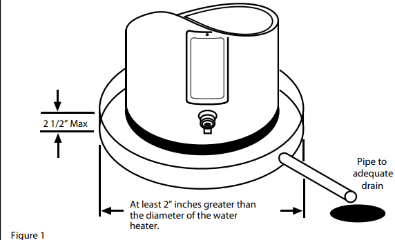
IMPORTANT: The water heater should be located in an area where leakage of the tank or connections will not result in damage to the area adjacent to the water heater or to the lower floors of the structure. Due to the normal corrosive action of the water, the tank will eventually leak after an extended period of time. Also, any external plumbing leak, including those from improper installation, may cause early failure of the water tank due to corrosion if not repaired. If the homeowner is uncomfortable with making the repair, a qualified person should be contacted. A suitable metal drain pan should be installed under the water heater as shown below. This metal drain pan is to protect the property from damage that may occur from normal condensate formation on the tank or leaks in the tank and pipe connections. The metal drain pan must limit the water level to a maximum depth of 2-1/2 inches and be two inches wider than the heater and piped to an adequate drain. Locate the water heater near a suitable indoor drain. Outdoor drains are subject to freezing temperatures which can obstruct the drain line. The piping should be at least 3/4” ID and pitched for proper drainage. Under no circumstance will the manufacturer or seller of this water heater be held liable for any water damage that is caused by your failure to follow these instructions.
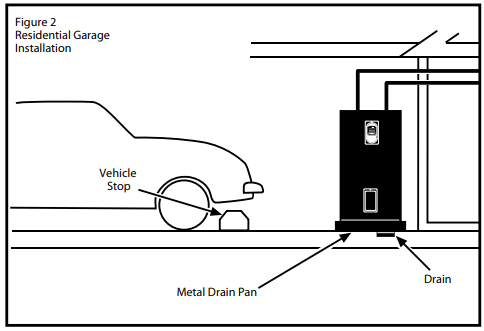
NOTE: Local codes and requirements in your area may require the water heater to be installed such that the bottom element is elevated from the floor at least 18 inches.The water heater shall be located so it is not subject to physical damage by moving vehicles or area flooding.
Water System Piping
Piping Installation
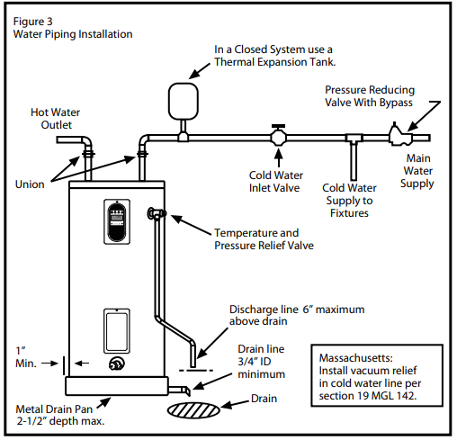
Piping, fittings, and valves should be installed according to the installation drawing (Figure 3). If the indoor installation area is subject to freezing temperatures, the water piping must be protected by insulation.
Water supply pressure should be around 50 to 60 psi and should not exceed 80 psi. If this occurs, a pressure-reducing valve should be installed in the cold water inlet line. This should be placed on the supply to the entire house in order to maintain equal hot and cold water pressures.
IMPORTANT:
Heat cannot be applied to the water fittings on the heater as they may contain nonmetallic parts. If solder connections are used, solder the pipe to the adapter before attaching the adapter to the hot and cold water fittings.
Always use a good grade of joint compound and be certain that all fittings are drawn up tight.
1. Install the water piping and fitting as shown in Figure 3. Connect the cold water supply (3/4” NPT) to the fitting marked “Cold”. Connect the hot water supply (3/4” NPT) to the fitting marked “Hot”.
IMPORTANT: Some models may contain energy-saving heat traps to prevent the circulation of hot water within the pipes. Do not remove these inserts.
2. The Installation of dielectric unions in both the hot and cold water supply lines is recommended for ease of removing the water heater for service or replacement.
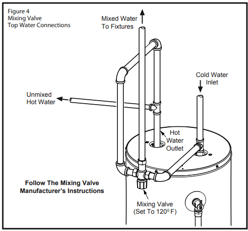
3. Some local codes may require, and the manufacturer of this water heater recommends, installing a mixing valve in the domestic hot water line as shown in Figure 4. These valves reduce the point-of-use temperature of the hot water by mixing cold and hot water and are readily available. Contact a licensed plumber or the local plumbing authority.
4. If installing the water heater in a closed water system, install a relief valve or expansion tank in the cold water line as specified under “Closed System/Thermal Expansion”.
5. Install a shut-off valve in the cold water inlet line. It should be located close to the water heater and be easily accessible. Know the location of this valve and how to shut off the water to the heater.
6. Install a discharge line from the temperature and pressure relief valve in the opening marked “T & P RELIEF VALVE”. Install as specified under “Temperature and Pressure Relief Valve”.
7. After the piping has been properly connected to the water heater, open the nearest hot water faucet. Then open the cold water shut-off valve and allow the tank to completely fill with water. To purge the lines of any excess air and sediment, keep the hot water faucet open for 3 minutes after a constant flow of water is obtained. Close the faucet and check all connections for leaks
Please note the following:
DO NOT install this water heater with iron piping. The system should be installed only with piping that is suitable for potable (drinkable) water such as copper, CPVC, or polyethylene (PEX).
DO NOT use PVC water piping.
DO NOT use any pumps, valves, or fittings that are not compatible with potable water.
DO NOT use valves that may cause excessive restriction to water flow. Use a full-flow ball or gate valves only.
DO NOT use tin-lead solder in potable water lines. Use 95/5 tin-antimony or other equivalent material.
DO NOT tamper with the energy smart module, electronic thermostat, temperature sensors, heating elements, electrical connections, or temperature and pressure relief valve. Tampering voids all warranties. Only a qualified person should service these components.
DO NOT use with piping that has been treated with chromate, boiler seal, or other chemicals.
DO NOT add any chemicals to the system piping which will contaminate the potable water supply.
Closed System/Thermal Expansion
Typically, a closed system includes a pressure-reducing valve (PRV) on the cold water inlet (supply line). As water is heated, it expands (thermal expansion). In a closed system, the volume of water will grow. As the volume of water grows, there will be a corresponding increase in water pressure due to thermal expansion. Thermal expansion can cause premature tank failure (leakage). This type of failure is not covered under the limited warranty. Thermal expansion can also cause intermittent temperature-pressure relief valve operation: water is discharged from the valve due to excessive pressure buildup. The temperature-pressure relief valve is not intended for the constant relief of thermal expansion. This condition is not covered under the limited warranty.
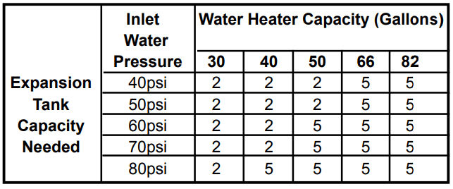
A properly-sized thermal expansion tank should be installed on all closed systems to control the harmful effects of thermal expansion. Contact a plumbing service agency or your retail supplier regarding the installation of a thermal expansion tank.
Expansion Tank Sizing Chart
A thermal expansion tank can help prevent damage to the water heater and other appliances (i.e.: washing machine, ice maker, dishwasher, etc.). IMPORTANT: Do not plug or remove the temperature and pressure relief valve (T&P valve).
Temperature and Pressure Relief Valve
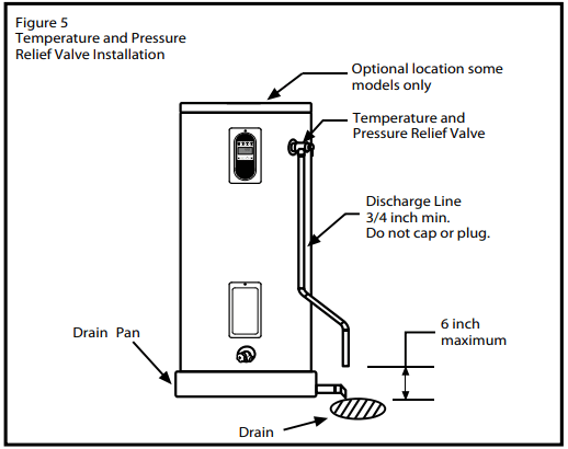
For protection against excessive pressures and temperatures, a temperature and pressure relief valve must be installed in the opening marked “T&P RELIEF VALVE” (See Figure 5). This valve must be design certifi ed by a nationally recognized testing laboratory that maintains periodic inspection of the production of listed equipment or materials as meeting the requirements for Relief Valves for Hot Water Supply Systems, ANSI Z21.22. The function of the temperature and pressure relief valve is to discharge water in large quantities in the event of excessive temperature or pressure developing in the water heater. The valve’s relief pressure must not exceed the working pressure of the water heater as stated on the rating plate.
IMPORTANT: Only a new temperature and pressure relief valve should be used with your water heater. Do not use an old or existing valve as it may be damaged or not adequate for the working pressure of the new water heater. Do not place any valve between the relief valve and the tank.
The Temperature & Pressure Relief Valve:
• Must be connected to an adequate discharge line.
• Must not be in contact with any electrical part.
• Must not be rated higher than the working pressure shown on the data plate of the water heater.
The Discharge Line:
• Must not be smaller than the pipe size of the relief valve or have any reducing coupling installed in the discharge line.
• Must not be capped, blocked, plugged, or contain any valve between the relief valve and the end of the discharge line.
• Must terminate a maximum of six inches above a fl oor drain or external to the building. In cold climates, it is recommended that the discharge pipe be termi- nated at an adequate drain inside the building.
• Must be capable of withstanding 250° F (121°C) without distortion.
• Must be installed to allow complete drainage of both the valve and discharge line.
T&P Relief Valve and Pipe Insulation:
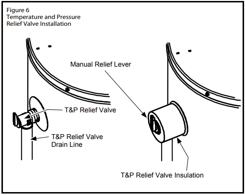
1. Locate the temperature and pressure relief valve on the water heater (also known as a T&P Relief Valve, (Figure 6).
2. Locate the slit running the length of the insulation.
3. Spread this slit open and slip it up under the T&P Relief Valve (See Figure 6). Apply gentle pressure to the insulation to ensure it is fully seated on the T&P Relief Valve. Once sealed, secure the insulation with a section of duct tape, electrical tape, or equivalent. IMPORTANT: The insulation or tape must not block the discharge opening or hinder access to the manual relief lever. Ensure a discharge pipe is installed into the T&P valve discharge opening per the instructions manual.
4. Locate the hot water (outlet) & cold water (inlet) pipes to the water heater.
5. Locate the slit running the length of a section of pipe insulation.
6. Spread the slit open and slip the insulation over the cold water (inlet) pipe. Apply gentle pressure along the length of the insulation to ensure it is fully seated around the pipe. Also, ensure that the base of the insulation is flush with the water heater. Once seated, secure the insulation with duct tape, electrical tape, or equivalent.
7. Repeat steps 5 through 6 for the hot water (outlet) pipe.
8. Add additional sections of pipe insulation as needed.
Solar Installation
If this water heater is used as a solar storage heater or as a backup for the solar system, the water supply temperatures to the water heater tank may be in excess of 120° F (48.8° C). A mixing valve or other temperature-limiting valve must be installed in the water supply line to limit the supply temperature to 120° F (48.8° C). Note: Solar water heating systems can often supply water with temperatures exceeding 180° F (82.2° C) and may result in water heater malfunction.
Electrical Requirements
If you lack the necessary skills required to properly install the electrical wiring to this water heater, do not proceed, but have a qualified electrician perform the installation.
When making the electrical connections, always make sure:
• The electrical supply has the proper overload fuse or circuit breaker protection.
• Wire sizes and connections comply with all applicable codes.
• Wiring is enclosed in approved conduit (if required by local codes).
• The water heater and electrical supply are properly grounded.
Always reference the wiring diagram for the correct electrical connection. The complete wiring diagram can also be found on the top of the water heater near the junction box cover.
When installing the electrical wiring to the water heater
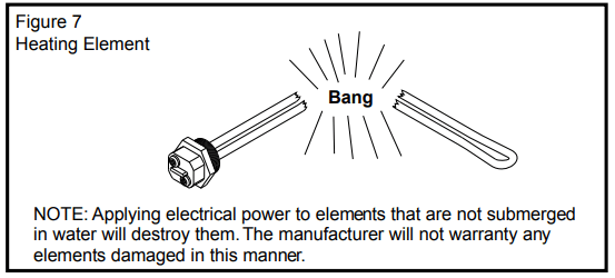
• Although this water heater is equipped with “Dry-fi re” protection, be sure the tank is completely filled with water, and all air is purged from the tank before making any electrical connections (See Figure 7).
1. Check and turn off power to the electrical wiring of the water heater before making any electrical connections to the water heater.
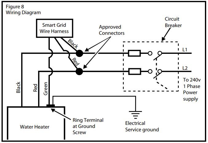
2. Remove the junction box cover that is secured by one screw (Figure 8A). Place the cover and screw aside and view the wiring diagram. Locate the four power wires inside the junction box (there will be TWO red wires and TWO black wires).
3. Connect the electrical supply to the water heater in accordance with the local utility requirements and codes. A standard 1/2-inch opening has been made in the junction box for the conduit connections (Figure 8A). NOTE: Use only 10 gauge solid copper wire for the electrical connections and an appropriate size double pole circuit breaker.
4. Ground the water heater by connecting the bare copper ground wire from the home’s electrical service to the green ground screw (located on the electrical junction box on top of the water heater). See Figures 8 and 8A.
5. There are TWO black wires and TWO red wires in the water heater. The smaller red and black wires are used by the Smart Grid connector.
6. Connect the black power wire from the home’s electrical service to the heater’s TWO black wires and secure with the appropriate size wire nut. When you are done, you will have THREE black wires under one wire nut.
7. Locate and connect the remaining power wire (usually red, but in your home, this wire may be some other color) from the home’s electrical service to the water heater’s TWO red wires and secure it with the appropriate size wire nut. When you are done, you will have THREE red wires under one wire nut (depending on the actual color of your home’s electric wiring).
8. Replace the junction box cover and secure with the screw removed in step 2.
9. Do not remove the Smart Grid cover from the Smart Grid connector (Figure 8A) unless this feature is be- ing used (see the “Smart Grid Technology” section this manual).
10. Insure that the water heater is completely full of water. Proceed to water heater start up in the “Operating Your Water Heater” section of this manual.
INSTALLATION CHECKLIST
Water Heater Location
Centrally located with the water piping system.
The flooring beneath the water heater must be able to support the weight of the water heater when filled with water.
Located indoors and in a vertical position. Protected from freezing temperatures.
Provisions are made to protect the area from water damage. Metal drain pan installed and piped to an adequate drain.
Sufficient room to service the water heater.
The site location must be free from any corrosive elements in the atmosphere such as sulfur, fluorine, and chlorine. These elements are found in aerosol sprays, detergents, bleaches, cleaning solvents, air fresheners, paint, and varnish removers, refrigerants, and many other commercial and household products.
Water System Piping
Temperature and pressure relief valve properly installed with a discharge pipe run to an adequate drain and protected from freezing (See Figure 3).
All piping is properly installed and free of leaks.
Suitable metal drain pan lines were installed and piped to an adequate drain (See Figure 3).
The heater completely filled with water (See Figure 3).
Closed system pressure buildup precautions were installed (See “Closed System/Thermal Expansion” section).
Mixing valve (when applicable) installed per manufacturer’s instructions (see Figure 4).
Electrical Connections
Wiring and connections comply with all applicable codes.
The water heater and electrical supply are properly grounded.
Proper overload fuse or circuit breaker protection installed.
OPERATING YOUR WATER HEATER
Water Heater Start-Up
1. Carefully read and understand the section, “Water Temperature Regulation” section of this manual. If the instructions are not clear, contact a qualifi ed person.
2. Make sure the water heater has been properly installed. See “Installing Your Water Heater” section.
3. Completely fi ll the tank water, Open faucet to allow air to purge (see page 5, step 7).
4. After the tank is completely fi lled with water, turn on power to the water heater at the breaker panel.
5. Power to the water heater will allow the water heater to run a system diagnostic. This typically takes eight minutes. Once complete, proceed to the next step. NOTE: if the system diagnostic yields any codes, reference the Diagnostic Code section in this manual.
6. Adjust the thermostat to the desired temperature setting as described under “Adjusting the User Inter- face Module/Operational Modes” section.
Safety Shut-Off
This water heater is designed to automatically shut-off in the event that the water temperature exceeds 180° F (82.2° C). A temperature limit switch, or ECO (Energy Cut Off), is used to shut off the power to the system if the water temperature exceeds 180° F or 82.2° C. The ECO can be reset by fi rmly pushing in the red reset button located on the electronic thermostat (see Figure 10A on page 12). If the ECO continues to shut-off the water heater contact a qualifi ed person.
Water Temperature Regulation
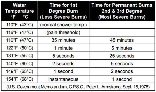
The water heater is adjusted to a temperature setting of no higher than 120° F when shipped from the factory. Water temperature can be regulated by adjusting the Energy Smart® Module to the preferred setting as shown in “Adjusting the Energy Smart® Module/Operational Mode”. The preferred starting point is 120° F. There is a hot water scald potential if the temperature set point is set too high.
Important: Adjusting the temperature past 120° F on the Energy Smart® Module will increase the risk of scald injury in the times shown below. The use of a mixing valve is recommended.
When leaving your home for extended periods (vacations, etc.) set the water heater to Vacation Mode. See the “Adjusting the Energy Smart® Module/Operational Modes” section. This will maintain the water at low temperatures with minimum energy losses and prevent the tank from freezing during cold weather.
NOTE: When returning from an extended stay remember to set the water heater back to the desired Operational Mode.
Adjusting the Energy Smart® Module/Operational Modes
Water Temperature Adjustment
IMPORTANT: Before attempting to adjust the thermostat, read the “Water Temperature Regulation” section on page 10. If the instructions are not clear, contact a qualified person.
The water temperature can be adjusted from 80° F to 150° F. Use the Up and Down Buttons to set the desired temperature.
Operating Mode Descriptions
The operating modes can be changed by touching the desired mode icon on the Energy Smart® Module (See Figure 10). NOTE: All buttons on the Energy Smart® Module are touch-sensitive and require only a light touch to actuate.
ENERGY SMART® - This mode is used to save energy by monitoring usage and adjusting the set point to match the water draw usage pattern (Temperature set point can be changed).
STANDARD - Pressing this button will allow the temperature set point to be set directly
VACATION MODE - The controller adjusts the water temperature to approximately 600F. This mode is recommended when the water heater is not in use for a long period of time. This mode minimizes energy consumption and prevents the water heater from freezing during cold weather.
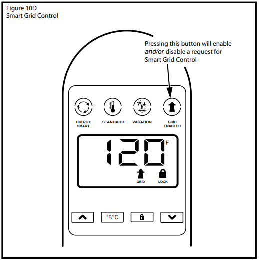
GRID ENABLED - Pressing this button will enable or disable a request for grid control (see page 13)
CONTROL PANEL LOCK - Holding this button for more than 3 seconds switches the lock mode on or off. When the User Module is locked, a symbol and “Lock” text will be visible on the display.
°F/°C - This button switches the display to show the set temperature in Fahrenheit or Celsius.
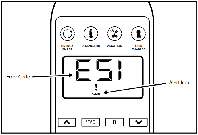
Fault condition will display an “E” followed by two digit fault code with Alert Icon flashing. (see diagnostic code chart page 17).
Element Functioning Icon - indicates power is on at either upper or lower element circuits and both are working properly
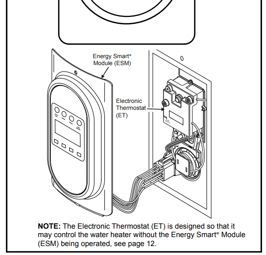
The Electronic Thermostat
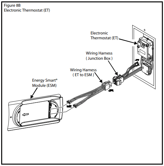
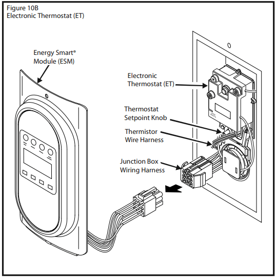
IMPORTANT: The Energy Smart® Module (ESM) must be removed before attempting to access the thermostat. NOTE: for the Electronic Thermostat (ET) changes to remain in effect the Energy Smart® Module (ESM) must not be reconnected, also read the “Water Temperature Regulation” under the “Operating Your Water Heater” section. If the instructions are not clear, contact a qualifi ed person. The Energy Smart® Module (ESM) is intended to serve as the primary interface for operating the water heater; however, the Electronic Thermostat (ET) may control the water heater in the absence of the Energy Smart® Module (ESM). The Electronic Thermostat consists of an electronics box that contains a low voltage power supply, the thermostat set point knob, relays to switch between the upper and lower heating elements, one control thermistor, a connector for the lower element control thermistor, microelectronics to convert the thermistor signals and perform switching and other logic functions, and a connector to tie the Electronic Thermostat (ET) to the Energy Smart® Module (ESM) located on the front of the water heater jacket. The majority of the self-diagnostics are located in the Electronic Thermostat (ET), including the dry-fi re protection intelligence. The thermostat circuit is designed so that when the upper heating element calls for heat, the power is directed to that element even if the lower element is also calling for heat.
Diagnostic LED Light
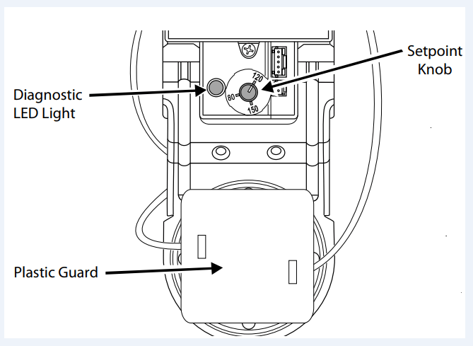
The Green/Red LED light indicates the status of the electronic thermostat (See Figure 10A).
• Green LED will signal normal operation. The green LED will blink 2 times per second to indicate that power is applied to the upper heating element and at a faster rate (4 times per second) to indicate that the lower heating element is powered.
• Red LED will flash error codes. If a fault is detected by the electronic thermostat, the LED light indicator will use the red LED to indicate the fault detected. The fl ash code sequence is to consist of 1/2 second fl ashes of the red LED each separated by a 1/2 second off period.
The number of flashes indicates the fault code number. (See diagnostic code chart section in this manual).
After the last 1/2 second “on” period, the LED will remain off until a total of 5 seconds has elapsed for the fault indication cycle (there is a 5 seconds delay before the fault fl ash pattern repeats). After the 5 seconds are completed, the fault indication cycle is repeated starting with the first 1/2 second-fl ash. The flash sequence will be repeated as long as the fault remains. Only one fault can be declared at a time. NOTE: the green LED is turned off when a fault code is being displayed, even though the heater may be operating in limp mode with an element on. See the diagnostic code chart section in this manual.
Overriding The Energy Smart® Module (ESM)
If the Energy Smart® Module (ESM) is not working, simply unplug the interface module and turn the set point knob on the Electronic Thermostat (ET) to the desired temperature (See Figures 10A & 10B). To replace a broken or damaged ESM module, see page 22 for ordering information.
Smart Grid Technology
The electric Smart Grid will enable signifi cant improvements in electric power reliability and quality through reduction of peak power demand, while providing consumers the knowledge and ability to manage their energy consumption and utility costs
According to the Department of Energy (DOE), since 1982 the growth in peak electricity demand has exceeded power transmission growth. This has caused more frequent blackouts and service interruptions, as well as an increase in the costly reserve capacity the power grid requires to meet higher peak demands. The increased demand for electrical power across the nation has also led to higher peak utility costs. Smart appliances are one way to help mitigate this problem. By using advanced digital communication technologies, smart appliances will be able to communicate with local power company or home energy management systems, and react accordingly to save energy and money. For example, during peak demand periods the water heater may pause or delay its power consumption and thus reduce the load on the smart utility grid. Additionally, smart appliances will also communicate with consumers to let them know how much energy they are consuming. This will eventually allow consumers to control their appliances, manage energy usage, and to ultimately save money
Smart Grid Control (Where Available)
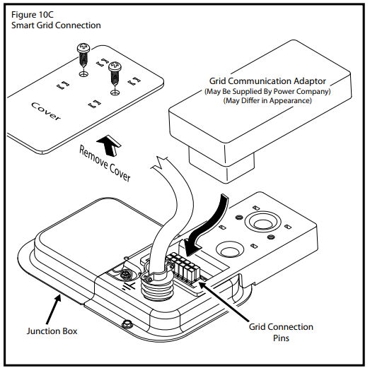
Where available, Grid Communication Adaptors may be supplied by the local power company or purchased from leading retailers. Please contact your local power company for more information. To activate SmartGrid Control, remove the cover over the grid connection pins and plug in the grid communication adaptor. See Figure 10C. NOTE: use only Whirlpool - approved grid communication adaptors. This will enable the power company to communicate the peak demand periods for the water heater’s power usage.
After this connection has been made, simply press the “Grid Enabled” button to enable and/ or disable a request for grid control. See Figure 10D. Enabling this feature will allow acceptance of the power company communication of grid management requests. Disabling this feature will allow the water heater to ignore grid management requests.
NOTE: Smart Grid will be disabled when the Energy Smart® Module (ESM) is disconnected from the junction box wiring harness (see page 12).
Operational Conditions
Anode Rod/Water Odor
Each water heater contains at least one anode rod, which will slowly deplete (due to electrolysis) prolonging the life of the water heater by protecting the glass-lined tank from corrosion. Adverse water quality, hotter water temperatures, high hot water usage, hydronic heating devices, and water softening methods can increase the rate of anode rod depletion. Once the anode rod is depleted, the tank will start to corrode, eventually developing a leak.
Certain water conditions will cause a reaction between the anode rod and the water. The most common complaint associated with the anode rod is a “rotten egg smell” produced from the presence of hydrogen sulfide gas dissolved in the water. CAUTION: Do not remove this rod permanently as it will void any warranties. A special anode rod may be available if water odor or discoloration occurs. NOTE: This rod may reduce but not eliminate water odor problems. The water supply system may require special filtration equipment from a water conditioning company to successfully eliminate all water odor problems.
Artificially softened water is exceedingly corrosive because the process substitutes sodium ions for magnesium and calcium ions. The use of a water softener may decrease the life of the water heater tank.
The anode rod should be inspected after a maximum of three years and annually thereafter until the condition of the anode rod dictates its replacement. NOTE: artificially softened water requires the anode rod to be inspected annually.
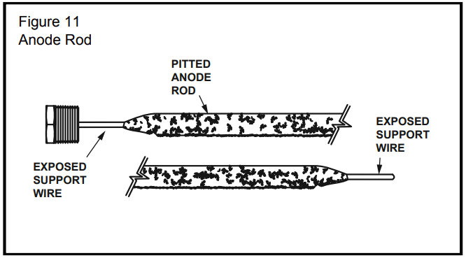
The following are typical (but not all) signs of a depleted anode rod:
• The majority of the rod's diameter is less than 3/8”.
• Significant sections of the support wire (approx. 1/3 or more of the anode rod’s length) are visible.
If the anode rod show signs of either or both it should be replaced (see Figure 11). NOTE: Whether re-installing or replacing the anode rod, check for any leaks and immediately correct if found.
See “Replacing the Anode Rod” in the maintenance section on page 15.
Water Heater Sounds
During the normal operation of the water heater, sounds or noises may be heard. These noises are common and may result from the following:
1. Normal expansion and contraction of metal parts during periods of heat-up and cool-down.
2. Sediment buildup in the tank bottom will create varying amounts of noise and may cause premature tank failure. Drain and flush the tank as directed under “Draining and Flushing”.
Stacking
Certain water usage patterns can cause the water temperature to exceed the thermostat setting. This is known as “Stacking”.
Stacking occurs when a series of short draws of hot water (3 gallons or less) are taken from the water heater tank. This causes increased cycling of the heater elements and can result in increased water temperatures at the hot water outlet. An anti-scald device is recommended in the hot water supply line to reduce the risk of scald injury. Use of a mixing valve is encouraged.
MAINTENANCE OF YOUR WATER HEATER
Draining and Flushing
It is recommended that the tank be drained and flushed every 6 months to remove sediment which may build up during operation. The water heater should be drained if being shut down during freezing temperatures. To drain the tank, perform the following steps:
1. Turn off the power to water heater.
2. Open a nearby hot water faucet until the water is no longer hot.
3. Close the cold water inlet valve.
4. Connect a hose to the drain valve and terminate it to an adequate drain or external to the building.
5. Open the water heater drain valve and allow all the water to drain from the tank. Flush the tank with water as needed to remove sediment.
6. Close the drain valve and refill the tank (open the cold water inlet valve), and restart the heater as directed in this manual. CAUTION: Do not turn on power to the water heater unless it is completely filled with water. To ensure that the tank is full, open a hot water faucet and allow water to run until the air is purged and the water flows uninterrupted from the faucet.
7. Turn the electrical power on to turn the water heater on. NOTE: the water heater will conduct a system diagnostic prior to operation.
If the water heater is going to be shut down for an extended period, the drain valve should be left open.
Replacing the Anode Rod
1. Turn off the power to the water heater.
2. Shut off the water supply and open a nearby hot water faucet to depressurize the water tank.
3. Drain approximately 5 gallons of water from the tank. (Refer to “Draining and Flushing” for proper procedures.) Close drain valve.
4. Remove the old anode rod (See Figure 11).
5. Use Tefl on® tape or approved pipe sealant on threads and install new anode rod.
6. Turn on the water supply and open a nearby hot water faucet to purge all air from the water system.
7. Restart the heater as directed in this manual. Turn the electrical power on to turn the water heater on. NOTE: the water heater will conduct a system diagnostic prior to operation. See the “Repair Parts Illustration” for the anode rod location on page 22.
Temperature and Pressure Relief Valve
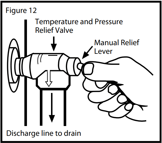
Manually operate the temperature and pressure relief valve at least once a year to make sure it is working properly. To prevent water damage, the valve must be properly connected to a discharge line which terminates at an adequate drain. Standing clear of the outlet (discharged water may be hot), slowly lift and release the lever handle on the temperature and pressure relief valve to allow the valve to operate freely and return to its closed position. If the valve fails to completely reset and continues to release water, immediately disconnect the electrical power, close the cold water inlet valve and call a qualified person.
Heating Element Replacement
Replacement heating elements must be of the same style and voltage/wattage rating as the ones originally in the water heater. This information can be found on the flange or terminal block of the element or on the water heater data plate.
1. Turn off the electric power to the water heater.
2. Drain the water heater as directed under “Draining and Flushing” section.
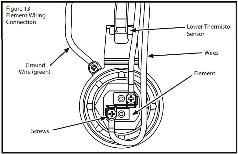
3. Remove the access cover(s), then remove the insula- tion and element cover(s). Remove the plastic guard covering electric wiring.
4. Disconnect the electric wires from the heating element (See Figure 13). Remove the screw-in element by turning the element counterclockwise with an SAE 1-1/2 inch socket wrench or use an element wrench. Remove the existing gasket.
5. Clean the area with a soft cloth to remove any debris where the gasket fits to the tank. If replacing the bottom element, remove the accumulated sediment on the bottom of the tank. Refer to “Draining and Flush- ing.”
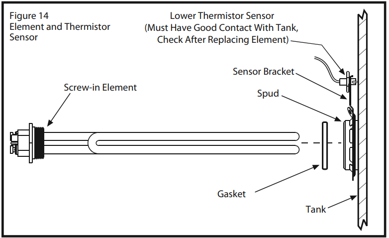
6. Make sure the replacement element has the correct voltage and wattage rating. Lubricate the new gasket with a few drops of dishwashing soap, position the new gasket on the element and insert it into the water heater tank (See Figure 14). Tighten the element by turning it clockwise until secure.
7. Close the drain valve. Open the nearest hot water faucet and allow the tank to fill completely with water. To purge the lines of any excess air and sediment debris, keep the hot water faucet open for 3 minutes after a constant flow of water is obtained. Close the faucet.
8. Check for leaks around element(s) and other connec- tions.
9. Connect the electric wires to the heater element. make sure all wires are secure. Reinstall plastic guard covering wiring.
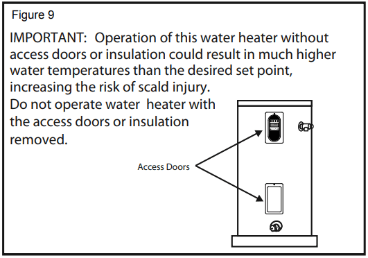
10. Replace the insulation and access door(s). IMPORTANT: Operation of this water heater without access doors or insulation could result in much higher temperatures than the desired set point, increasing the risk of scald injury. Do not operate water heater with the access doors or insulation removed.
11. Reconnect the electric power to the water heater.
12. Turn the electrical power on to turn the water heater on. NOTE: the water heater will conduct a system diagnostic prior to operation.
Diagnostic Code Chart Energy Smart® Module (ESM)
IMPORTANT: Before attempting to adjust the thermostat, read the “Water Temperature Regulation” section page 10.
The Electronic Thermostat (ET) is designed so that it may control the water heater without the Energy Smart® Module (ESM) being operated, see page 12.
If the instructions are not clear, contact a qualifi ed person.
(ESM) ERROR CODE
INDICATES
CORRECTIVE ACTION*
E01 with an alert Icon flashing.
Dry-fire, electrical power on with the tank not completely full of water
1. Turn off electrical power at breaker, add water.
2. Turn on electrical power at breaker.
3. See “Water Heater Start-Up” on page 10.
E02 with an alert Icon flashing
Water temperature exceeded high limit.
1. Turn off electrical power at the breaker.
2. Press the reset button (see Figure 10A).
3. Turn on electrical power at breaker.
4. If error returns call a service technician for assistance.
E03 with an alert Icon flashing
Upper thermistor sensor failure. (Note: Upper thermistor sensor is part of the ET)
1. Turn off electrical power at the breaker.
2. Replace Electronic Thermostat (ET).
3. Turn on electrical power at breaker.
E04 with an alert Icon flashing.
Upper element circuit failure. (Note: Lower element is still operable)
1. Turn off electrical power at the breaker.
2. Check element circuits for resistance of 5-25 ohms (replace if required).
3. Check wires at elements and Electronic Thermostat (ET) for damage. If this 4 flashes condition continues, replace Electronic Thermostat (ET).
4. Turn on electrical power at breaker.
E05 with an alert Icon flashing.
Lower element circuit failure. (Note: Upper element is still operable)
1. Turn off electrical power at the breaker.
2. Check element circuits for resistance of 5-25 ohms (replace if required).
3. Check wires at elements and Electronic Thermostat (ET) for damage. If this 5 flashes condition continues, replace Electronic Thermostat (ET).
1. Turn off electrical power at the breaker. Now turn on electrical power to see if error clears. If error has not cleared, replace Electronic Thermo- stat (ET).
2. Turn on electrical power at breaker.
E07 with an alert Icon flashing
Lower thermistor sensor failure.
1. Turn off electrical power at the breaker.
2. Check electrical connections at Electronic Thermostat (ET).
3. Replace Lower Thermistor Sensor.
4. Turn on electrical power at breaker.
E08 with an alert Icon flashing
Energy Smart® Module (ESM) failure.
1. Turn off electrical power.
2. Check wires at the interface module for damage.
3. If this 8 flashes condition continues, replace module (ESM).
4. See “Overriding The Interface Module (ESM)” by unplugging from the Electronic Thermostat (ET) on page 12. NOTE: Electronic Thermostat (ET) will continue to be operate, hot water will still be available.
5. Turn on electrical power at breaker.
E09 with an alert Icon flashing.
E10
E11
E12
Electronic Thermostat (ET) error
1. Turn off electrical power.
2. Check wiring at Electronic Thermostat (ET) for damage.
3. Turn on electrical power at breaker.
4. If this code flashes condition continues, replace the Electronic Thermostat (ET).
E51 with an alert Icon flashing
A failure to communicate with the Electronic Thermostat (ET).
1. Turn off electrical power at the breaker, check all electrical connections, and wiring for damage.
2. Replace the Electronic Thermostat (ET).
3. Turn on electrical power at breaker.
E52 with an alert Icon flashing.
Energy Smart® Module (ESM) is receiving the wrong data from the Electronic Thermostat (ET).
1. Turn off electrical power at the breaker, check all electrical connections, and wiring for damage.
2. Replace the Energy Smart® Module (ESM), if this does not correct the problem, also replace Electronic Thermostat (ET).
E71 with an alert Icon flashing.
Energy Smart® Module (ESM) thermistor failure.
1. Turn off electrical power at the breaker, check all electrical connections, and wiring for damage.
2. Turn on electrical power at breaker.
3. If error returns call service technician for assistance.
Diagnostic Code Chart Electronic Thermostat (ET)
IMPORTANT: Before attempting to adjust the thermostat, read the “Water Temperature Regulation” section page 10.
The Electronic Thermostat (ET) is designed so that it may control the water heater without the Energy Smart® Module (ESM) being operated, see page 12.
If the instructions are not clear, contact a qualifi ed person
(ESM) ERROR CODE
(ET) DIAGNOSTIC LED
INDICATES
CORRECTIVE ACTION*
LIGHT ON (Green Flash)
Normal operation.
None
NO LIGHT
No electrical power to control board or diagnostic LED light burned out.
1. Check for blown fuses or tripped breaker.
2. If diagnostic LED light is burned out, replace Electronic Thermostat (ET).
E01
1 FLASH (Red)
Dry-fire, electrical power on with the tank not completely full of water.
1. Turn off electrical power at breaker, add water.
2. Turn on electrical power at breaker.
3. See “Water Heater Start-Up” on page 10.
E02
2 FLASHES (Red)
Water temperature exceeded high limit
1. Turn off electrical power at the breaker.
2. Press the reset button (see Figure 10A).
3. Turn on electrical power at breaker.
4. If error returns call a service technician for assistance.
E03
3 FLASHES (Red)
Upper thermistor sensor failure. (Note: Upper thermistor sensor is part of the ET)
1. Turn off electrical power at the breaker.
2. Replace Electronic Thermostat (ET).
3. Turn on electrical power at breaker.
E04
4 FLASHES (Red)
Upper element circuit failure. (Note: Lower element is still operable)
1. Turn off electrical power at the breaker.
2. Check element circuits for resistance of 5-25 ohms (replace if required).
3. Check wires at elements and Electronic Thermostat (ET) for damage. If this 4 flashes condition continues, replace Electronic Thermostat (ET).
4. Turn on electrical power at breaker.
E05
5 FLASHES (Red)
Lower element circuit failure. (Note: Upper element is still operable)
1. Turn off electrical power at the breaker.
2. Check element circuits for resistance of 5-25 ohms (replace if required).
3. Check wires at elements and Electronic Thermostat (ET) for damage. If this 5 flashes condition continues, replace Electronic Thermostat (ET).
1. Turn off electrical power at the breaker. Now turn on electrical power to see if error clears. If error has not cleared, replace Electronic Thermo- stat (ET).
2. Turn on electrical power at breaker
E07
7 FLASHES (Red)
Lower thermistor sensor failure
1. Turn off electrical power at the breaker.
2. Check electrical connections at Electronic Thermostat (ET).
3. Replace Lower Thermistor Sensor.
4. Turn on electrical power at breaker.
E08
8 FLASHES (Red)
Energy Smart® Interface Module(ESM) failure.
1. Turn off electrical power.
2. Check wires at the interface module for damage.
3. If this 8 flashes condition continues, replace module (ESM).
4. See “Overriding The Interface Module (ESM)” by unplugging from the Electronic Thermostat (ET) on page 12. NOTE: Electronic Thermostat (ET) will continue to be operate, hot water will still be available.
5. Turn on electrical power at breaker
E9
E10
E11
E12
9, 10, 11 or 12 FLASHES (Red)
Electronic Thermostat (ET) error
1. Turn off electrical power.
2. Check wiring at Electronic Thermostat (ET) for damage.
3. Turn on electrical power at breaker.
4. If this code flashes condition continues, replace the Electronic Thermostat (ET).
TROUBLESHOOTING
PROBLEM
POSSIBLE CAUSE(S)
CORRECTIVE ACTION*
NO HOT WATER
1. No power to heater.
2. High temperature limit shut-down.
3. Defective sensor.
1. Refer to “E02” of Diagnostic Code Chart- page 17.
2. Refer to “E03 or E07” of Diagnostic Code Chart- page 17.
3. Refer to “No Light” of Diagnostic Code Chart- page 19.
INSUFFICIENT HOT WATER
1. Defective lower element.
2. Temperature set too low.
3. Sediment or lime in tank.
4. Defective Dip Tube.
5. Heater too small for job.
6. Wrong piping connections.
7. Leaking faucets and/or plumbing system.
8. Wasted hot water.
9. Long runs of exposed pipe.
10.Hot water piping on outside wall.
1. Refer to “E05” of Diagnostic Code Chart- page 17.
2. Set temperature to desired setting.
3. Drain, determine if water treatment is needed.
4. Replace Dip Tube.
5. Check and Install adequate water heater.
6. Correct piping.
7. Repair faucets and any leaks in the plumbing system.
8. Reduce hot water usage.
9. Insulate piping.
10.Insulate piping.
HIGH OPERATION COSTS
1. Temperature set too high.
2. Sediment or lime in tank.
3. Heater too small for job.
4. Leaking faucets and/or plumbing system.
5. Wasted hot water.
6. Long runs of exposed piping.
7. Hot water piping in exposed wall.
8. Elements covered with sediment or lime.
1. Lower temperature control or change to Energy Smart® Mode.
2. Drain, Flush-Provide water treatment if needed.
3. Install adequate heater.
4. Repair faucets and any leaks in the plumbing system.
5. Advise customer.
6. Insulate piping.
7. Insulate piping.
8. Replace elements.
SLOW HOT WATER RECOVERY
1. Upper element defective.
2. Leaking faucets and/or plumbing system.
1. Refer to “E04” of Diagnostic Code Chart- page 17.
2. Repair faucets and any leaks in the plumbing system.
DRIP FROM T&P VALVE
1. Excessive water pressure.
2. Closed system.
3. Defective T&P valve.
1. Use pressure reducing valve and pressure relief valve (See page 6).

 to set the desired temperature.
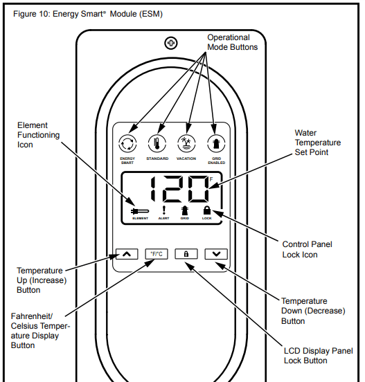
 ENERGY SMART® - This mode is used to save energy by monitoring usage and adjusting the set point to match the water draw usage pattern (Temperature set point can be changed).
 STANDARD - Pressing this button will allow the temperature set point to be set directly
 VACATION MODE - The controller adjusts the water temperature to approximately 600F. This mode is recommended when the water heater is not in use for a long period of time. This mode minimizes energy consumption and prevents the water heater from freezing during cold weather.
 GRID ENABLED - Pressing this button will enable or disable a request for grid control (see page 13)
 CONTROL PANEL LOCK - Holding this button for more than 3 seconds switches the lock mode on or off. When the User Module is locked, a symbol and “Lock” text will be visible on the display.
 °F/°C - This button switches the display to show the set temperature in Fahrenheit or Celsius.
 Fault condition will display an “E” followed by two digit fault code with Alert Icon flashing. (see diagnostic code chart page 17).
 Element Functioning Icon - indicates power is on at either upper or lower element circuits and both are working properly
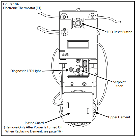
 After this connection has been made, simply press the “Grid Enabled” button to enable and/ or disable a request for grid control. See Figure 10D. Enabling this feature will allow acceptance of the power company communication of grid management requests. Disabling this feature will allow the water heater to ignore grid management requests.