Review all of the instructions before you begin work. If you aren’t sure that you can safely and properly do this work yourself, call your Lowe’s® store to arrange for Professional Installation (you may also call a qualified person of your choice, such as a licensed plumber or electrician, to have the work done). Improper installation can damage the water heater, your home and other property, and can present risks of serious injury or death.
Check with your local and state authorities for any local or state codes that apply to your area. In the absence of local and state codes, follow National Fire Protection Association (NFPA-70) and the current editions of the National Electric Code (NEC) and the International Plumbing Code (IPC). The instructions in this manual comply with national codes, but the installer is responsible for complying with local codes. Massachusetts code requires this water heater to be installed in accordance with Massachusetts 248-CMR 2.00 and 248-CMR 5.00: State Plumbing Code. Other local and state authorities may have similar requirements or other codes applicable to the installation of this water heater.
Before you start, be sure you have, and know how to use, the following tools and supplies:
Plumbing tools and supplies appropriate for the type of water pipes in your home
Threaded connectors (Figure 1) for the cold and hot water pipes
For homes plumbed with plastic pipe, use threaded connectors suitable for the specific type of plastic pipe used: CPVC and PEX (crosslinked polyethylene). Do not use PVC pipe.
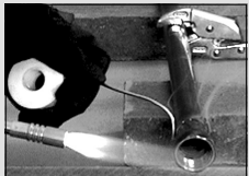
For homes with copper pipes, you may purchase connector kits with compression fittings that don’t require soldering (Figure 1). Compression fittings are easier to install than soldering copper pipes.
Teflon® tape or pipe joint compound approved for potable water
Tools to make the electrical connections (for example, screwdrivers, wire strippers)
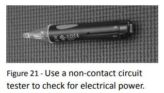
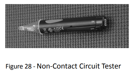
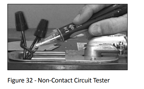
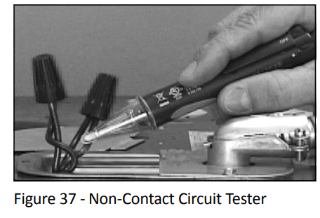
Non-Contact circuit tester to check for power (Figure 2)
Water Pressure Gauge (Figure 4)
Recommended Accessories:
Suitable drain pan (Figure 6 on page 8)
Automatic leak detection and shutoff device
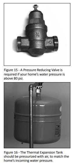
Pressure Reducing Valve (Figure 3 on page 6)
Thermal Expansion Tank (Figure 5 on page 7)
Point-of-use Thermostatic Mixing Valves (Figure 7 on page 8)
INSTALLATION
Follow these steps for proper installation on:
Step 1: Verify that your home is equipped and up-to-date for proper operation
Installing a new water heater is the perfect time to examine your home’s plumbing system and make sure the system is up to current code standards. There have likely been plumbing code changes since the old water heater was installed. We recommend installing the following accessories and any other needed changes to bring your home up to the latest code requirements.
Use the checklist below and inspect your home. Install any devices you need to comply with codes and assure that your new water heater performs at its best. Check with your local plumbing official for more information.
Water pressure
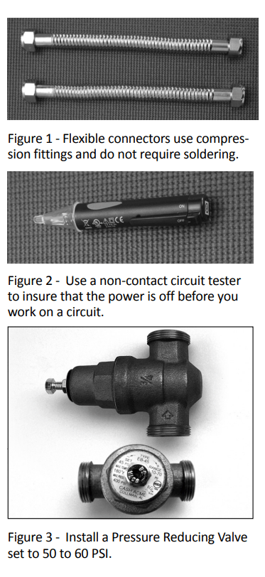
We recommend checking your home’s water pressure with a pressure gauge (Figure 4.) Most codes allow a maximum incoming water pressure of 80 psi. We recommend a working pressure no higher than 50-60 psi.
HOW: Purchase an inexpensive water pressure gauge available at Lowe’s®. Connect the Water Pressure Gauge to an outside faucet and measure the maximum water pressure experienced throughout the day (highest water pressures often occur at night).
Figure 4 - Use a Water Pressure Gauge to make sure your home’s water pressure is not too high.
To limit your home’s water pressure: Locate your home’s Pressure Reducing Valve (PRV) on the main incoming (cold) water supply line and adjust the water pressure control to between 50 and 60 psi. If your home does not have a Pressure Reducing Valve, install a PRV on the home’s main water supply line and set it to between 50 and 60 psi. Pressure Reducing Valves are available at Lowe’s® .
BACKGROUND: Over the years, many utilities have increased water supply pressures so they can serve more homes. In some homes today, pressures exceed 100 psi. High water pressures can damage water heaters, causing premature leaks. If you have replaced toilet valves, had a water heater leak, or had to repair appliances connected to the plumbing system, pay particular as ention to your home’s water pressure. When purchasing a PRV, make sure the PRV has a built-in bypass.
Water pressure increase caused by thermal expansion
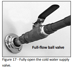
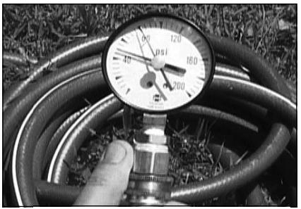
Verify that you have a properly sized Thermal Expansion Tank (Figure 5). We recommend installing an expansion tank if your home does not have one. Codes require a properly pressurized, properly sized Thermal Expansion Tank in almost all homes. (See photo on inside front cover.)
Figure 5 - A Thermal Expansion Tank helps protect the home’s plumbing system from pressure spikes.
HOW: Connect the Thermal Expansion Tank (available at Lowe’s® ) to the cold water supply line near the water heater. The expansion tank contains a bladder and an air charge. To work properly, the Thermal Expansion Tank must be sized according to the water heater’s tank capacity and pressurized to match the home’s incoming water pressure. Refer to the installation instructions provided with the Thermal Expansion Tank for installation details.
BACKGROUND: Water expands when heated, and the increased volume of water must have a place to go, or thermal expansion will cause large increases in water pressure (despite the use of a Pressure Reducing Valve on the home’s main water supply line). The Safe Drinking Water Act of 1974 requires the use of backflow preventers and check valves to restrict water from your home reentering the public water system. Backflow preventers are often installed in water meters and may not be readily visible. As a result, most all plumbing systems today are now “closed,” and almost all homes now need a Thermal Expansion Tank.
A Thermal Expansion Tank is a practical and inexpensive way to help avoid damage to the water heater, washing machine, dishwasher, ice maker and even toilet valves. If your toilet occasionally runs for no apparent reason (usually briefly at night), that may be due to thermal expansion increasing the water pressure temporarily.
Water pipe and tank leaks
Leaks from plumbing pipes or from the water heater itself can damage property and could cause a fire risk.
Install an automatic leak detection and shutoff device (available at Lowe’s® ). These devices can detect water leaks and can shut off the water heater’s water supply if a leak occurs.
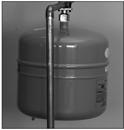
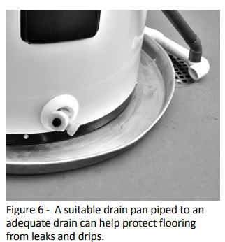
Install a suitable drain pan (available at Lowe’s® ) under the water heater (Figure 6) to catch condensation or leaks in the piping connections or tank. Most codes require, and we recommend, installing the water heater in a drain pan that is piped to an adequate drain. The drain pan must be at least two inches wider than the diameter of the water heater. Install the drain pan so the water level would be limited to a maximum depth of 1-3/4”.
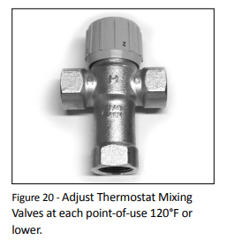
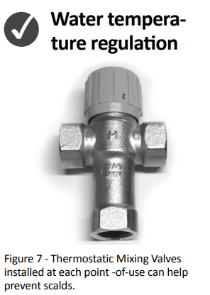
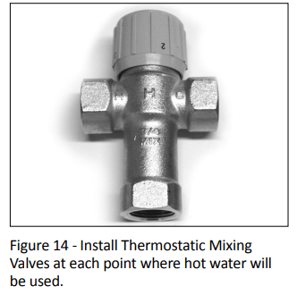
Install Thermostatic Mixing Valves (Figure 7) to regulate the temperature of the water supplied to each point of use (for example, kitchen sink, bathroom sink, bath, shower). Consult the valve manufacturer’s instructions or a qualified person.
WARNING! Even if the water heater thermostat is set to a relatively low temperature, hot water can scald. Install Thermostatic Mixing Valves at each point of use to reduce the risk of scalding (page 4).
BACKGROUND: A Thermostatic Mixing Valve, installed at each point of use, mixes hot water from the water heater with cold water to more precisely regulate the temperature of hot water supplied to fixtures. If you aren’t sure if your plumbing system is equipped with properly installed and adjusted Thermostatic Mixing Valves at each point where hot water is used, contact a qualified person for more information.
Step 2: Verify that the location is appropriate
Before installing your water heater, ensure that:
The water heater will be:
Installed indoors close to the center of the plumbing system.
In a suitable drain pan piped to an adequate floor drain or external to the building (Figure 6 on page 8).
In an area that will not freeze
In an area that is suitable for installing the water heater vertically
The location has adequate space (clearances) for periodic servicing.
The floor can support the weight of a full water heater.
Your area is not prone to earthquakes. If it is, use special straps as required by local building codes.
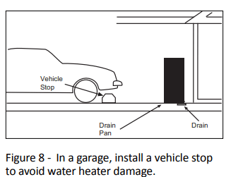
The location is not prone to physical damage by vehicles, flooding, or other risks.
Avoid locations such as aƫ cs, upper floors, or where a leak might damage the structure or furnishings. Due to the normal corrosive action of water, the tank will eventually leak. To minimize property damage from leaks, inspect and maintain your water heater in accordance with this manual’s instructions. Install a suitable drain pan under the water heater piped to an adequate drain. Inspect the drain pan, pipes, and surrounding area regularly and fix any leaks found. Drain pans are available at Lowe’s®. Leaks are frequently in the plumbing system itself and not the water heater
Step 3: Removing the old water heater
Read each installation step and decide if you have the necessary skills to install the water heater. Only proceed if you can safely perform the work. If you are not comfortable, have a qualified person perform the installation.
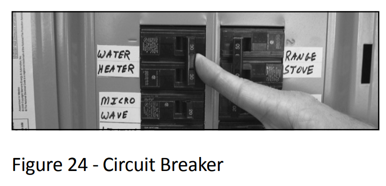
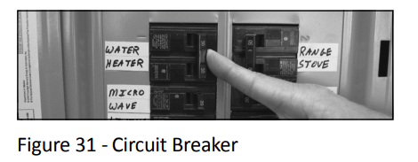
Locate the water heater’s circuit breaker and turn it OFF (or remove the circuit’s fuses).
On the old water heater, remove the electrical junction box access panel. Using a non-contact circuit tester, check the wiring to make certain the power is OFF.
Disconnect the electrical wires.
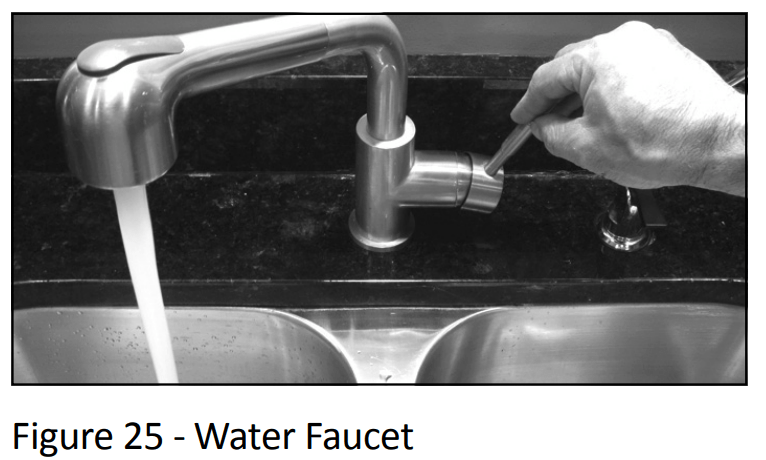
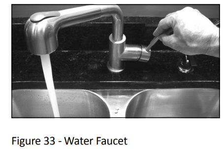
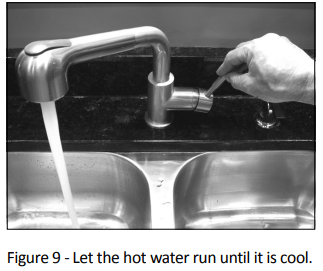
Open a hot water faucet and let the hot water run until it is cool (This may take 10 minutes or longer).
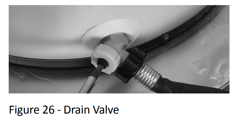
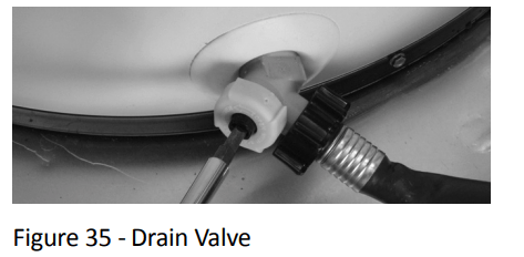
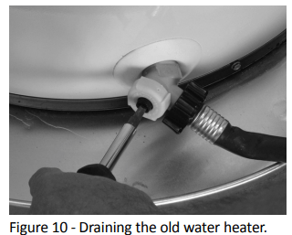
Connect a garden hose to the drain valve and place the other end of the hose in a drain, outside, or a bucket. (Note that sediment in the bottom of the tank may clog the valve and prevent it from draining. If you can’t get the tank to drain, contact a qualified person.
Turn the cold water supply valve OFF.
Open the drain valve on the water heater.
Also open a hot water faucet to help the water in the tank drain faster.
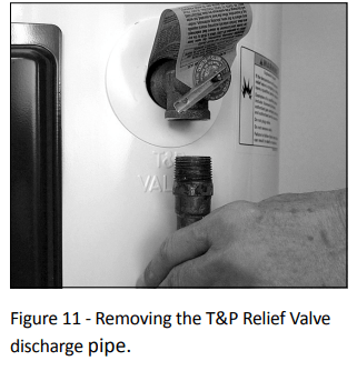
When the tank is empty, disconnect the Temperature & Pressure (T&P) Relief Valve discharge pipe. You may be able to reuse the discharge pipe, but do not reuse the old T&P Relief Valve. A new T&P Relief Valve comes installed on your water heater (or on some models, is in the carton with the water heater).
Disconnect the water pipes. Many water pipes are connected by a threaded union which can be disconnected with wrenches. If you must cut the water pipes, cut the pipes close to the water heater’s inlet and outlet connections, leaving the water pipes as long as possible. If necessary, you can make them shorter later when you install the new water heater.
Remove the old water heater.
Step 4: Installing the new water heater
Completely read all instructions before beginning. If you are not sure if you can complete the installation, DO NOT RETURN THIS UNIT TO THE STORE. Seek assistance from any of the following sources:
Lowe’s® Professional Installation is available for this product and the work is guaranteed. Call your Lowe’s® store to have this water heater installed.
Schedule an appointment with a qualified person to install your water heater.
Call our Technical Assistance Hotline at 1-877-817-6750
Install a suitable drain pan that is piped to an adequate drain.
Set the water heater in place taking care not to damage the drain pan. NOTICE: Most codes require seƫ ng the water heater in a suitable drain pan piped to an adequate drain. The drain pan helps avoid property damage which may occur from condensation or leaks in the piping connections or tank. The drain pan must be at least two inches wider than the diameter of the water heater. Install the drain pan so the water level is limited to a maximum depth of 1-3/4”.
Verify that the water heater is properly set in place. Check that:
The T&P Relief Valve will not be in contact with any electrical parts.
There is adequate space to install the T&P Relief Valve discharge pipe and that it can be piped to a separate drain (and not into the drain pan).
There is adequate access and space around the water heater for future maintenance.
Step 5: Connect the Temperature and Pressure (T&P) Relief Valve/Pipe
Most T&P Relief Valves are pre-installed at the factory. In some cases, they are shipped in the carton and must be installed in the opening marked and provided for this purpose and according to local codes.
WARNING! To avoid serious injury or death from explosion, install a T&P Relief Valve according to the following instructions:
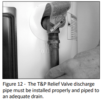
If your water heater does not have a factory installed T&P Relief Valve, install the new T&P Relief Valve that came with your water heater. Do not reuse an old T&P Relief Valve. Install a T&P Relief Valve discharge pipe according to local codes and the following guidelines:
The discharge pipe should be at least 3/4” inside diameter and sloped for proper drainage. Install it to allow complete drainage of both the T&P Relief Valve and the discharge pipe.
The discharge pipe must withstand 250°F (121°C) without distortion. Use only copper or CPVC pipe. Do not use any other type of pipe, such as PVC, iron, flexible plastic pipe, or any type of hose.
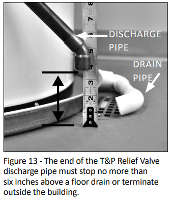
Terminate the discharge pipe a maximum of six inches above a floor drain or outside the building. Do not drain the discharge pipe into the drain pan; instead pipe it separately to an adequate drain. In cold climates, terminate the discharge pipe inside the building to an adequate drain. Outside drains could freeze and obstruct the drain line. Protect the drain from freezing.
Do not place any valve or other restriction between the tank and T&P Relief Valve. Do not cap, block, plug, or insert any valve between the T&P Relief Valve and the end of the discharge pipe. Do not insert or install any reducer in the discharge pipe.
Step 6: Install shutoff and tempering valves
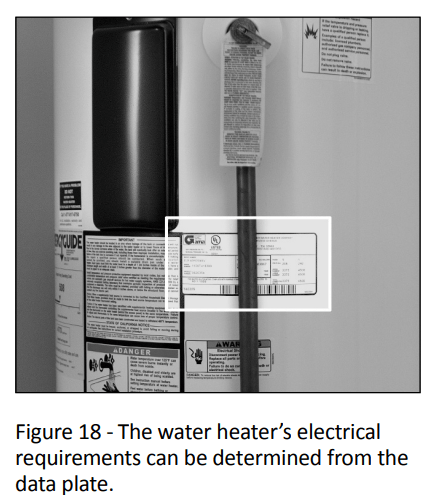
If one is not already installed, install a manual shutoff valve in the cold water line that supplies the water heater. Install the shutoff valve near the water heater so that it is readily accessible. Only use valves that are compatible with potable water. Use only full-flow ball or gate valves. Other types of valves may cause excessive restriction to the water flow.
Install a Thermostatic Mixing Valve at each point of use (for example, kitchen sink, bathroom sink, bath, shower). Consult the valve manufacturer’s instructions or a qualified person.
For water heaters that are fed by a solar water heating system (or any other pre-heating system), always install a Thermostatic Mixing Valve or other temperature limiting device in the inlet water supply line to limit water supply inlet temperature to 120°F. Solar water heating systems can supply water with temperatures exceeding 170°F and may result in water heater malfunction.
Step 7:
Connect the water supply Determine the type of water pipes in your home. Most homes use copper water pipes, but some use CPVC or cross-linked polyethylene (PEX). Use fittings appropriate for the type of pipe in your home. Do not use iron or PVC pipe – they are not suitable for potable water.
Connect the cold water supply using 3/4 inch National Pipe Thread “NPT” to the cold water inlet nipple. For ease of removing the water heater for service or replacement, connect the water pipes with a coupling called a union. We recommend using a dielectric-type union (available at Lowe’s® ). Dielectric unions can help prevent corrosion caused by tiny electric currents common in copper water pipes and can help extend the life of the water heater. IF YOU HAVE COPPER PIPES: If your home has copper water pipes, you can solder the water pipe connections or use compression fittings which don’t require soldering. Compression fittings are easier to install than soldering pipe. Check with local plumbing officials to determine what types of pipe materials are suitable for your location. Do not use lead-based solder . NOTICE: Do not solder pipes while they are attached to the water heater. The water heater’s inlet and outlet connections contain non-metallic parts which could be damaged. The proper way to connect the water heater to copper water pipes is as follows:
Solder a short length of pipe (about a foot or so) to a threaded adapter using only 95/5 tin antimony or equivalent solder. Attach the threaded adapters to the water heater’s connections (using Tefl on® tape or pipe joint compound). Connect the home’s water pipes by soldering, keeping the connections at the water heater cool with wet rags. NOTICE: Most water heater models contain energy-saving heat traps in the inlet and outlet connections. Do not remove the heat traps.
Connect the hot water supply using 3/4 inch NPT to the hot water outlet. Follow the same connection guidelines as for the cold water supply.
Install insulation (or heat tape) on the water pipes especially if the indoor installation area is subject to freezing temperatures. Insulating the hot water pipes can increase energy efficiency.
Double check to make sure the hot and cold water pipes are connected to the correct hot and cold water fittings on the water heater.
If needed, install (or adjust) the home’s Pressure Reducing Valve to 50-60 psi and install a Thermal Expansion Tank.
Step 8: Verify connections and completely fill tank
To remove air from the tank and allow the tank to fill completely with water, follow these steps:
Remove the aerator at the nearest hot water faucet. This allows any debris in the tank or plumbing system to be washed out.
Turn the cold water supply back on.
Open a hot water faucet and allow the water to run until it flows with a full stream.
Let the water run full stream for three full minutes.
Close the hot water faucet and replace the aerator.
Check inlet and outlet connections and water pipes for leaks. Dry all pipes so that any drips or leaks will be apparent. Repair any leaks. Almost all leaks occur at connections and are not a tank leak.
Step 9: Make electrical connections
Be sure the electrical power to the water heater is turned OFF at the circuit breaker panel (or remove the circuit’s fuses).
Using a non-contact circuit tester, check the wiring to make certain the power is OFF.
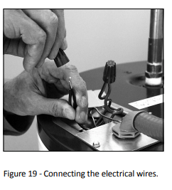
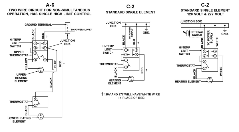
Check the water heater’s data plate and ensure that the home’s voltage, wiring size (ampacity) and circuit breaker rating and type are correct for this water heater. Refer to the wiring diagram located on the water heater for the correct electrical connections. Ensure that wire sizes, types, and connections comply with all applicable local codes. In the absence of local codes, follow NFPA-70 and the current edition of the National Electric Code (NEC).
Remove the cover on the electrical junction box on the top of the water heater.
Install wiring in an approved conduit (if required by local codes). Use a UL-listed or CSA-approved strain relief to secure the electrical wiring to the water heater.
Connect the ground wire to the green ground screw. Connect the home’s two power wires to the water heater’s two power wires. Use suitable wire nuts or other approved means to make the power connections.
Replace the junction box cover and secure with the screws provided.
Step 10: Adjusting the Temperature
With the installation steps completed, you may adjust the water heater’s temperature seƫ ng if desired.
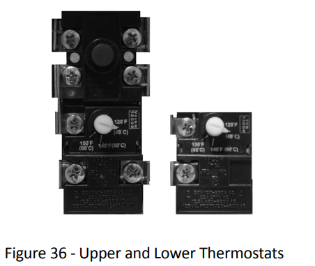
1. Set the thermostat(s) to desired temperature. The thermostat(s) on this water heater have been factory set to approximately 120°F to reduce the risk of scald injury. You may wish to set a higher temperature to provide hot water for automatic dishwashers or laundry machines, to provide more hot water capacity, and to reduce bacterial growth. Higher tank temperatures (140° F) kill bacteria that cause a condition known as “smelly water” and can reduce the levels of bacteria that cause water-borne diseases.
WARNING! Higher temperatures increase the risk of scalding, but even at 120°F, hot water can scald (page 4).
If you increase the water heater’s temperature setting, install Thermostatic Mixing Valve(s) at each point of use to reduce the risk of scalding.
To adjust the water heater’s thermostat:
Be sure the electrical power to the water heater is turned OFF at the circuit breaker panel (or remove the circuit’s fuses).
WARNING! Working near an energized circuit can result in severe injury or death from electrical shock. Check wires with a circuit tester to make sure power is off.
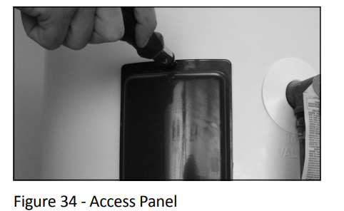
Remove the upper and lower access panels and fold away the insulation.
Turn the water temperature dial clockwise ( >>) to increase the temperature, or counter clockwise ( << ) to decrease the temperature. Adjust both thermostats to the same temperature setting. To avoid a shortage of usable hot water, do not adjust the upper thermostat to a temperature setting that is higher than the lower thermostat’s temperature setting.
NOTE: Most models have two thermostats, but some models may only have one. If your water heater has only one thermostat, it is located behind the lower access panel.
Fold the insulation back in place and replace the access panels.
WARNING! Be sure panels are secured to reduce the risk of fire and electric shock.
2. Turn the electric power back on.
3. Wait for the water to heat up. It may take several hours for a tank of cold water to heat up. If you have no hot water after two hours, refer to “TROUBLESHOOTING” Section on page 17. WARNING! If you have increased the temperature seƫ ng and the Thermostatic Mixing Valves are not set properly (or not installed) you could scald yourself while checking the temperature.
4. Check water temperature at several points of use in your home (for example, bathtub faucet, shower, or lavatory sink) and adjust the Thermostatic Mixing Valves as needed. If you aren’t sure how to adjust the Thermostatic Mixing Valve settings, or aren’t sure if you have Thermostatic Mixing Valves, contact a qualified person.
Step 11: Operation
The water heater is now ready for normal operation. To keep your water heater working safely and efficiently and extend its life, perform maintenance according to the schedule on page 21.
Vacation: To save energy, lower the temperature seƫ ng on the thermostat(s) if you plan to be gone for an extended time. Follow the instructions in Step 10 for adjusting the thermostat to a lower temperature setting before you leave and to properly raise the temperature setting when you return.
C AUTION! Hydrogen gas builds up in a hot water system when it is not used for a long period (two weeks or more). Hydrogen gas is extremely flammable. If the hot water system has not been used for two weeks or more, open a hot water faucet for several minutes at the kitchen sink before using any electrical appliances connected to the hot water system. Do not smoke or have an open flame or other ignition source near the faucet while it is open.
TROUBLESHOOTING
PROBLEM
POSSIBLE CAUSE(S) See explanations on the following pages.
CORRECTIVE ACTION
NO HOT WATER
No power to water heater
Burned out upper heating element (Dry Fired)
Energy Cut Off Switch tripped
Faulty Thermostatic Mixing Valve
Non-Functioning upper thermostat
Leak in plumbing system
Check for blown fuses or tripped circuit breaker. Check for power.
Replace upper heating element.
See page 19, step 5
Check hot water at other faucets
Check/replace upper thermostat. (See page 23)
Check hot water side of home’s plumbing system for leaks.
INSUFFICIENT HOT WATER
Thermostats set too low
Non-Functioning lower heating element
Water heater’s capacity too small (or usage too high)
Thermostactic Mixing Valve faulty/set too low
Non-Functioning lower thermostat
Hot and cold pipe connections reversed
Leak in plumbing system
Melted dip tube
Set thermostats to desired temperature.
Replace lower heating element.
Install adequately sized water heater (or reduce usage).
Check hot water at other faucets
Replace lower thermostat
Correct piping.
Check hot water side of home’s plumbing system for leaks.
Check/replace dip tube.
SLOW HOT WATER RECOVERY
Low supply voltage
Malfunctioning lower heating element
Check power (voltage).
Check lower element and replace if burned out.
TEMPERATURE TOO HIGH
Non-functioning thermostat
Grounded/shorted heating element
Thermostatic Mixing Valve faulty/set too high
Replace thermostat
Replace heating element.
Check hot water at other faucets.
LOW WATER PRESSURE
Partially closed supply valve.
Excessive water pressure
Thermal expansion
Debris under valve seat
See Low Water Pressure section
Use Pressure Reducing Valve set to 50-60 psi.
Install a Thermal Expansion Tank
See page 20
DRIPS FROM T&P RELIEF VALVE
WATER ODOR
Bacteria in the water
See Water Odor section
WARNING! Working near an energized circuit can result in severe injury or death from electrical shock. WARNING! When you are finished, be sure all covers are secured to reduce the risk of fire and electric shock.
No Hot Water
The most likely reasons for an electric water heater to produce NO hot water are:
No electric power—a common problem with new installations
Burned out upper element (Dry Fired) — a common problem with new installations
Tripped Energy Cut Off (red button on upper thermostat)
The water heater’s inlet and outlet connections are reversed (usually only in new installations)
Broken upper thermostat (or wiring)
A leak in the hot water side of the plumbing system that exceeds the water heater’s heating capacity and makes it appear that the water heater is producing little to no hot water
Follow these steps to diagnose and correct common electrical problems:
1. Check the electric power to the water heater. No hot water is often caused by a problem with the home’s electrical wiring or circuit breakers. You’ll need a non-contact circuit tester. Follow these guidelines:
Locate the water heater’s circuit breaker and turn it off (or remove the circuit’s fuses).
Locate the electrical junction box on top of the water heater and remove the cover.
Identify the two power wires. The power wires are usually black/black or black/red—the green or copper wire is the ground wire.
Turn the circuit breaker back on (or install the fuses) and check the power on both incoming power wires using a non-contact circuit tester.
Turn the power off and replace the cover on the electrical junction box.
If the water heater is not getting powered, contact a qualified person to have your home’s wiring or circuit breakers checked.
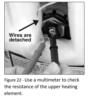
2. Check the upper heating element. If the water heater is getting electrical power, check to see if the upper heating element has burned out. If the upper element is burned out, you’ll have no hot water. To check the upper element, you’ll need a multimeter capable of reading resistance.
Turn the power OFF at the circuit breaker or remove fuses.
Remove the upper access panel.
Remove the insulation to access the upper thermostat and heating element.
3. Check the top two screws of the upper thermostat using a non-contact circuit tester and confi rm that power is off (screw terminals 1 and 3 in photo on next page).
With the electrical power off , remove the two power wires from the upper heating element.
4. Check the resistance of the upper heating element using a multimeter. Measure the resistance between the two screw terminals on the upper heating element. A good element will have a resistance ranging between 5 and 25 Ohms. If the resistance is:
Outside this range. Replace the element (see the Routine Maintenance section on page 21). On a new water heater, a burned out upper heating element is almost always caused by turning the power on before the tank was completely full of water (Dry Fire). (See Step 8 in the Installtion section.)
Within this range. Reattach the power wires, making sure the wires are in good condition and the connections are clean and right. Next, check the following:
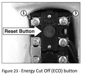
5. Check/Reset Energy Cut Off (ECO) Button.
The Energy Cut Off (ECO) shuts off power to the water heater’s elements if the temperature of the water in the tank gets too hot. If the ECO has tripped, you’ll have no hot water. A tripped ECO can usually be reset, but you should have a qualified person investigate the cause of the overheating and repair the problem. Do not turn the power back on until the cause of the overheating has been identified and repaired.
To check the Energy Cut Off (ECO)
Turn off the power to the water heater. WARNING! Working near an energized circuit can result in severe injury or death from electrical shock. Check power wires in the electrical junction box with a non-contact circuit tester to make sure power is off .
Press the red ECO reset button (see photo above).
The ECO was tripped if you hear a click when it is reset. In most cases, a tripped ECO indicates that the tank overheated due to a problem with one of the elements or thermostats—have a qualified person check the upper and lower elements and thermostats and replace if necessary.
The ECO was not tripped if you didn’t hear a click. In that case, the upper thermostat should be checked by a qualified person.
Replace the insulation and the upper access panel.
Turn off the power to the water heater.
WARNING! Be sure all covers are secured to reduce the risk of fire and electric shock
Insufficient Hot Water or Slow Hot Water Recovery
WARNING! Because of the increased risk from scalding, if you set the water heater’s thermostat(s) higher than 120°F, Thermostatic Mixing Valves at each point of use are particularly important (page 4).
If the hot water is simply not warm enough, there are several possible causes:
Faulty Thermostatic Mixing Valve in a faucet or shower control (check other faucets in the house for hot water)
One (or both) of the thermostats set too low
Water heater’s capacity too small (or usage too high)
Reversed plumbing connections or melted dip tube (usually found soon after new installation)
Plumbing leak
Bad lower heating element (or lower thermostat)
Low supply voltage
Thermostatic Mixing Valves. If the hot water is simply not warm enough, make sure the faucet you are checking doesn’t have a defective Thermostatic Mixing Valve. Many shower controls now have built-in mixing valves. If these devices fail, they can reduce the amount of hot water the shower or faucet delivers even though there is plenty of hot water in the tank. Always check the water temperature at several faucets to make sure the problem is not in a faucet or shower control.
Thermostats set too low. If the water temperature at several faucets is too cool, adjust the thermostat(s) according to the instructions in Step 10 of the Installation section of this manual.
Undersized water heater. If your water heater runs out of hot water too quickly, it may be too small for your needs. If the water heater is old, consider replacing it with a larger model. If the water heater is in good condition, you may be able to meet your family’s hot water needs with the existing water heater by installing Thermostatic Mixing Valves at each point-of-use and then turning the thermostat(s) to a higher seƫ ng. See “Step 10” on page 15.
You can also reduce your home’s hot water needs by washing clothes in cold water, installing flow restrictors on shower heads, repairing leaky faucets, and taking other conservation steps.
Reversed connections or melted dip tube. Check the hot and cold connections and make sure your home’s hot water pipe is connected to the hot water outlet on the water heater. Usually, reversed connections are found soon after the installation of a new unit. If copper pipes were soldered while they were attached to the water heater, the dip tube may have melted. The dip tube is a long plastic tube inside the tank aƩ ached to the cold water inlet. If the dip tube has melted, it can be replaced by removing the cold water inlet connection, removing the old dip tube and installing a new one.
Plumbing leak. Even a small leak in the hot water side of the home’s plumbing system can make it appear that the water heater is producing little to no hot water. Locate and repair the leak.
Lower heating element not working. If the lower heating element (or, more rarely, the lower thermostat) is not working, you will have some hot water but not as much as before. Because the lower element does most of the work, the lower element usually wears out before the upper element. Replace the lower element and/or thermostat if necessary
Temperature Too High
If the water temperature is too hot:
Install or adjust the Thermostatic Mixing Valves for each point-of-use (see manufacturer’s instructions), or
Adjust the thermostat(s) on the water heater (see Step 10 in the installation section of this manual).
A nonfunctioning thermostat or a shorted heating element can cause extremely hot water. If the Temperature and Pressure Relief Valve (T&P Valve) releases large amounts of very hot water, it is likely due to a shorted heating element, or more rarely a nonfunctioning thermostat or the thermostat does not fit snuggly against the tank. Very high water temperatures can also cause the Energy Cut Off (ECO) to trip (see page 19). Turn power off until this problem is fixed.
Low Water Pressure
Check both the cold and hot water at a sink to determine if the lower pressure is only on the hot water side. If both hot and cold faucets have low pressure, call your local water utility. If the low pressure is only on the hot water side, the primary causes of this are:
Melted heat traps or dip tube. Soldering copper pipes while they are connected to the water heater can melt the heat traps inside the hot and cold water connections or the dip tube (cold water side). Melted heat traps or a melted dip tube can restrict the flow of hot water. If that’s the case, replace the heat traps or dip tube.
Partially closed supply valve. Open the water heater’s supply valve fully
Drips from T&P Relief Valve Discharge Pipe
A small amount of water dripping from the Temperature and Pressure (T&P) Relief Valve usually means the home’s water pressure is too high or you need a properly sized and pressurized Thermal Expansion Tank. Refer to Step 1 in the Installation section of this manual for more information. A large amount of hot water coming from the T&P discharge pipe may be due to the tank overheating.
WARNING! Do not cap or plug the T&P relief valve or discharge pipe, and do not operate the water heater without a functioning T&P Relief Valve - this could cause an explosion.
Water pressure too high. High water pressure can cause the T&P Relief Valve to drip. Install a Pressure Reducing Valve (PRV) on the main cold water supply line. Adjust the PRV to between 50 and 60 psi.
Thermal Expansion Tank. Install a Thermal Expansion Tank. If a Thermal Expansion Tank is already installed and the T&P Relief Valve discharge pipe drips, the Thermal Expansion Tank may be pressurized to the wrong pressure or the internal bladder may be defective. Refer to the instructions that came with the Thermal Expansion Tank for more information.
Debris. In rare cases, debris can stick inside the T&P Relief Valve preventing the valve from seating fully. In that case, the T&P Relief Valve discharge pipe will drip. You may be able to clear debris from the T&P Relief Valve by manually operating the valve, allowing small quanties of water to flush out the debris. See the label on the T&P Relief Valve for instructions.
If the water pressure is between 50 and 60 psi, a Thermal Expansion Tank is installed and properly pressurized, and the valve has been cleared of any debris, and it still drips, the valve may be broken—have a qualified person replace the T&P relief valve.
Water Odor
Harmless bacteria normally present in tap water can multiply in water heaters and give off a “rotten egg” smell. Although eliminating the bacteria that causes “smelly water” with a Chlorination system is the only sure treatment, in some cases, the standard anode rod that came with your water heater can be replaced with a special zinc anode rod which may help reduce or eliminate the odor. Contact a qualified person.
NOTE: To protect the tank, an anode rod must be installed in the water heater at all times or the warranty is void.
In cases where the “rotten egg” smell is pronounced, you can raise the tank temperature to 140°F in order to reduce bacteria growth in the tank.
WARNING! Because higher temperatures increase the risk of scalding, if you set the thermostat(s) higher than 120°F, Thermostatic Mixing Valves at each point-of-use are particularly important (page 4).
MAINTENANCE
Routine Maintenance
Routine maintenance will help your water heater last longer and work better. If you can’t perform these routine maintenance tasks yourself, contact a qualified person.
Water Heater Maintenance: After the first six months, drain and flush the water heater and inspect the anode rod. Depending on the hardness of your water, repeat this process at least annually, or more frequently if needed. From time to time, you may need to replace a heating element or a thermostat. All three maintenance tasks are described below.
Draining and Flushing the Water Heater: Tap water contains minerals that can form lime deposits on heating elements or sediment in the boƩ om of the tank. The amount of lime deposits or sediment depends on the hardness of your tap water. The rate at which sediment builds up depends on water quality and hardness in your area, the temperature settings, and other variables. We recommend draining and flushing the water heater after the first six months of operation to determine the amount of sediment buildup. Draining sediment extends the life of the tank, heating elements, and drain valves.
In areas with very hard water, remove and check the heating elements whenever you drain the tank. If you have heavy lime deposits on heating elements, you will need to replace them more often.
Sediment may form large masses that can prevent the tank from draining. Have a qualified person use a de-liming agent suitable for potable water to remove the sediment buildup.
In most cases, it is easier and cheaper to replace lime-encrusted elements than trying to remove heavy lime deposits.
To drain and fl ush the tank:
1. Locate the water heater’s circuit breaker and turn it OFF (or remove the circuit’s fuses).
2. Open a hot water faucet and let the hot water run until it is cool.
WARNING! Be sure the water runs cool before draining the tank to reduce the risk of scalding.
3. Connect a garden hose to the drain valve and place the other end of the hose in a drain, outside, or in buckets.
4. Turn the cold water supply valve OFF.
5. Open the drain valve on the water heater.
6. Open a hot water faucet to help the water in the tank drain faster.
NOTICE: DO NOT turn electrical power back on unless the tank is completely full of water.
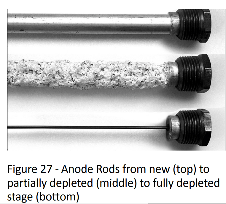
7. Remove and inspect the anode rod (see Repair Parts Illustration on back cover for location of the anode rod). Replace the anode rod if it is depleted. Turn power off . Run hot water until it’s cool. Turn cold water supply valve off . Open a hot water faucet to depressurize tank. Locate and remove the black plastic cover marked “Anode” Use a “key hole” saw or similar tool to remove the foam insulation covering the anode rod. Once the anode rod is exposed, use a 1 1/16” socket wrench with an extension to remove it. Inspect the anode rod and replace if depleted. Apply Tefl on® tape or pipe joint compound and reinstall the anode rod tightly. It is not necessary to replace the foam removed to access the anode. Turn cold water supply valve on. When hot water runs full, close hot water faucet. Check for leaks and repair if necessary. Turn power on.
Anode Rod. The anode rod is a sacrificial metal rod that helps reduce corrosion and premature failure (leaks) in the tank. The anode rod is a consumable item. Inspect the anode rod after the first six months of operation when you drain and flush the tank. Replace the anode rod if it is substantially worn out or depleted. Thereafter, inspect the anode rod annually or more frequently if needed. If you use a water softener, your anode rod will deplete faster than normal. Inspect the anode rod more frequently, replacing the anode rod as needed. Obtain new anode rods from your local Lowe’s® or have a qualified person replace it. (Anode rods are a consumable item and are not covered under warranty).
8. If the sediment was present when the tank was drained, flush the tank by opening the cold water supply valve and letting the water run until no more sediment drains from the tank. Close the drain valve when you are done. NOTICE: Do not turn power back on until the tank is completely full of water. For complete instructions on filling the tank, follow Step 8 in the Installation section.
9. Refill the tank by opening the cold water supply valve. Make sure a hot water faucet is open and the drain valve is closed. Allow the hot water to run full for at least three minutes to make sure the tank has all the air removed and is completely full of water. Failure to perform this step can cause the upper heating element to burn out. Once you are certain the tank is completely full of water, close the hot water faucet.
10. Restore power to the water heater. It may take two hours for the tank to heat up.
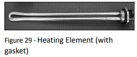
Replacing the Heating Element
WARNING! Working on an energized circuit can result in severe injury or death from electrical shock. Turn power off. Check wires with a noncontact circuit tester to make sure power is off . When you are finished, be sure all covers are secured to reduce the risk of fire and electric shock.
If you are not comfortable replacing a heating element or thermostat yourself, have this work done by a qualified person. To replace the heating element, you’ll need the following tools and supplies:
Always turn power OFF and check the power wires with a non-contact circuit tester before working on the water heater.
Check your water heater’s data plate for the correct wattage and voltage. Heating elements are available Lowe’s® .
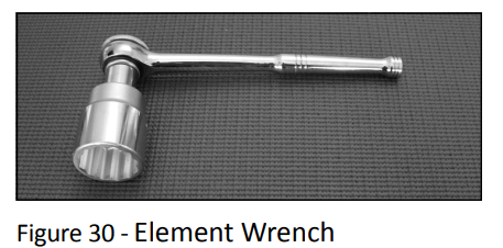
Some regular sockets (1 1/2 inch) may work, but regular sockets are often beveled and may slip. Inexpensive element wrenches are available at Lowe’s® .
Garden hose to drain the tank
Hand dishwashing soap to lubricate the gasket
A clean cloth to clean the threaded opening
A flat blade and a Phillips screwdriver
Steps for Replacing the Heating Element:
1. Turn the power OFF at the circuit breaker or remove fuses.
2. Open the electrical junction box on top of the water heater. Using a non-contact circuit tester, check the power wires to make certain the power is OFF
3. Open a hot water faucet and let the hot water run until it is cool.
WARNING! Be sure the water runs cool before draining the tank to reduce the risk of scalding
4. Connect a garden hose to the drain valve and place the other end of the hose in a drain or outside (or use buckets). Turn OFF the cold water valve that supplies the water heater. Open the drain valve on the water heater. Opening a hot water faucet will help the tank drain faster.
5. Remove the upper or lower access panel on the water heater, and then fold back the insulation and remove the plastic element/thermostat cover.
6. With the tank drained and power off, remove the power wires from the element you intend to replace.
7. Remove the bad element using an element wrench.
8. Make sure the new element is the correct replacement by referring to the water heater’s data plate for voltage and waƩ age information.
9. Clean the threads in the tank opening with a rag. Insert the new element equipped with a rubber gasket. NOTE: Use a drop of hand dishwashing liquid to lubricate the gasket to help avoid damaging the gasket as it is being tightened. Tighten with an element wrench. NOTICE: Do not turn power back on until the tank is completely full of water. For complete instructions on filling the tank, follow Step 8 in the Installation section.
10. Refill the tank by opening the cold water supply valve. Make sure a hot water faucet is open and the drain valve is closed. Allow the hot water to run full for at least three minutes to make sure the tank has all the air removed and is completely full of water. Failure to perform this step can cause the upper heating element to burn out. Once you are certain the tank is completely full of water, close the hot water faucet.
11. Check the newly installed element for leaks. If a leak is present, tighten the element until the leak stops. If you cannot stop the leak, drain the tank and remove the element. Inspect the gasket for damage. If the gasket is damaged, replace the gasket and re-install the element.
12. Once the element is successfully installed and there are no leaks, replace the power wires, thermostat cover, insulation, and access panel. Make sure all wire connections are right. Replace the cover on the electrical junction box.
13. Restore power to the water heater. It may take two hours for the tank to heat up.
Replacing the Thermostat
WARNING! Working on an energized circuit can result in severe injury or death from electrical shock. Turn power off. Check wires with a non-contact circuit tester to make sure power is off. When you are finished, be sure all covers are secured to reduce the risk of fire and electric shock.
To replace the thermostat, you’ll need the following tools and supplies:
A non-contact circuit tester. Always turn power OFF and check with a non-contact circuit tester before working on the water heater.
A replacement thermostat (available at Lowe’s® ). Note that the upper and lower thermostats are different (above). Some models only have one thermostat.
A business card to check the gap between the thermostat and the tank
Tape and a permanent marker to mark the wires
A flat blade and a Phillips screwdriver
Steps for Replacing the Thermostat:
Turn the power OFF at the circuit breaker or remove fuses. NOTICE: It is not necessary to drain the tank to replace a thermostat.
Open the electrical junction box on top of the water heater. Using a non-contact circuit tester, check the power wires to make certain the power is OFF.
Remove the upper or lower access panel on the water heater and carefully fold back the insulation and plastic element/ thermostat cover.
Make sure the replacement thermostat matches the original thermostat.
Mark the wires with tape so you’ll know how to put them back on.
Disconnect the wires from the bad thermostat and remove the thermostat from the metal mounting clip.
Install the new thermostat in the metal mounting clip.
Make sure the new thermostat fits snuggly against the tank. You should NOT be able to slip a business card between the thermostat and the tank. If you can, bend the thermostat mounting clip until the thermostat fits tightly against the tank.
Attach the wires following the wiring diagram on the water heater’s label. Make sure all wire connections are tight.
Replace the plastic element/ thermostat cover, insulation, and access panel.
Replace the cover on the electrical junction box.
Restore power to the water heater. It may take two hours for the tank to heat up.
T&P Relief Valve Maintenance
Read and follow the operating and annual maintenance instructions provided by the manufacturer of the T&P Relief Valve (yellow label attached to T&P Relief Valve). Minerals in the water can form deposits that cause the valve to stick or create blocked passages, making the T&P Relief Valve inoperative. Follow these guidelines:
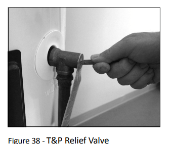
At least annually, operate the T&P Relief Valve manually to ensure the waterways are clear and the valve mechanism moves freely (above). Before operating the valve manually, check that it will discharge in a place for secure disposal. If water does not flow freely from the end of the discharge pipe, turn OFF the power to the water heater. Call a qualified person to determine the cause.
WARNING! Hot water will be released. Before operating the T&P relief valve manually, check that it will discharge in a safe place. If water does not flow freely from the end of the discharge pipe, turn the power to the water heater OFF. Call a qualified person to determine the cause.
At least every five years, have a qualified person inspect the T&P Relief Valve and discharge pipe. Damage caused by corrosive water conditions, mineral deposits, or other problems can only be determined when a qualified person removes and inspects the valve and its components.
Note that a dripping T&P Relief Valve is usually caused by the home’s water pressure being too high or the lack of a Thermal Expansion Tank. If your T&P Relief Valve drips, see page 20
 . NOTICE: Do not solder pipes while they are attached to the water heater. The water heater’s inlet and outlet connections contain non-metallic parts which could be damaged. The proper way to connect the water heater to copper water pipes is as follows: