
OWNER’S MANUAL
www.lg.com
P/NO : MFL68680222 (1510-REV04)
55EG9600
65EG9600
55EF9500
65EF9500
55EG9200
*MFL68680222*
Please read this manual carefully before operating your set and retain it
for future reference.
ENG
ENGLISH
2
IMPORTANT SAFETY INSTRUCTIONS
IMPORTANT SAFETY INSTRUCTIONS
Always comply with the following precautions to avoid dangerous situations and ensure peak performance
of your product.
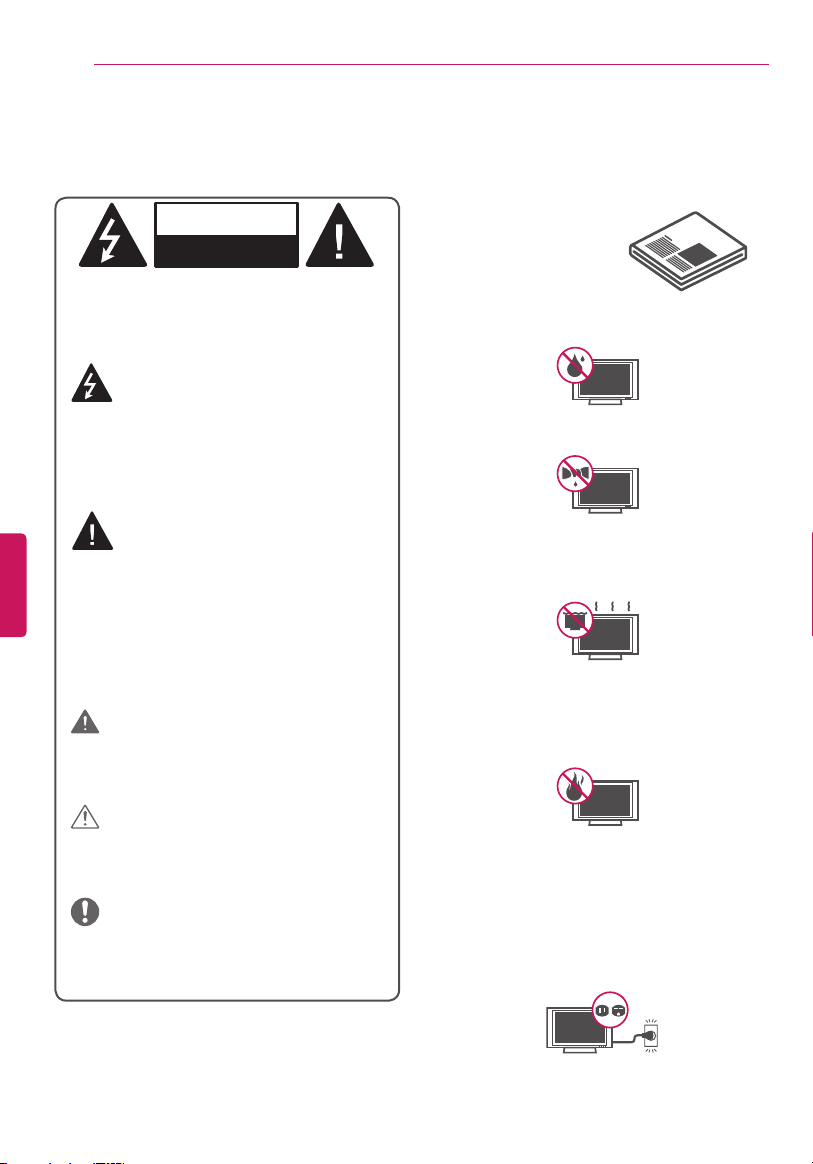
Do not use this apparatus near water.
Short-circuit
Breaker
Power Supply
Clean only with dry cloth.
Short-circuit
Breaker
Power Supply
Do not block any ventilation openings.
Install in accordance with the manufacturer’s
instructions.
Short-circuit
Breaker
Power Supply
Do not install near any heat sources such
as radiators, heat registers, stoves, or other
apparatus (including amplifiers) that produce
heat.
Short-circuit
Breaker
Power Supply
Do not defeat the safety purpose of the polarized
or grounding-type plug. A polarized plug has two
blades with one wider than the other. A grounding
type plug has two blades and a third grounding
prong. The wide blade or the third prong are
provided for your safety. If the provided plug does
not fit into your outlet, consult an electrician for
replacement of the obsolete outlet.
Short-circuit
Breaker
Power Supply
Read these instructions.
Keep these instructions.
Heed all warnings.
Follow all instructions.
WARNING/CAUTION
RISK OF ELECTRIC SHOCK
DO NOT OPEN
TO REDUCE THE RISK OF ELECTRIC SHOCK DO
NOT REMOVE COVER (OR BACK).
NO USER SERVICEABLE PARTS INSIDE.
REFER TO QUALIFIED SERVICE PERSONNEL.
WARNING/CAUTION
RISK OF ELECTRIC SHOCK
DO NOT OPEN
The lightning flash with arrowhead
symbol within an equilateral triangle is
intended to alert the user to the
presence of uninsulated dangerous voltage
within the product’s enclosure that may be of
sufficient magnitude to constitute a risk of
electric shock to persons.
WARNING/CAUTION
RISK OF ELECTRIC SHOCK
DO NOT OPEN
The exclamation point within an
equilateral triangle is intended to alert
the user to the presence of important
operating and maintenance (servicing)
instructions in the literature accompanying the
appliance.
WARNING/CAUTION
- TO REDUCE THE RISK OF FIRE AND ELECTRIC
SHOCK, DO NOT EXPOSE THIS PRODUCT TO
RAIN OR MOISTURE.
WARNING
If you ignore the warning message, you may
be seriously injured or there is a possibility of
accident or death.
CAUTION
If you ignore the caution message, you may
be slightly injured or the product may be
damaged.
NOTE
The note helps you understand and use the
product safely. Please read the note carefully
before using the product.
Short-circuit
Breaker
Power Supply
WARNING: This product contains chemicals known
to the State of California to cause cancer and birth
defects or other reproductive harm.
Wash hands after handling.
ENGENGLISH
3
IMPORTANT SAFETY INSTRUCTIONS
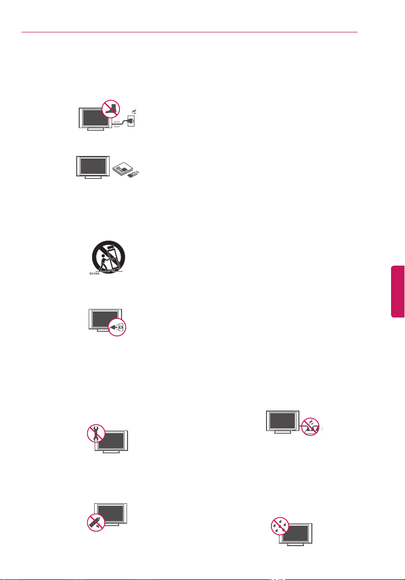
Protect the power cord from being walked on
or pinched particularly at plugs, convenience
receptacles, and the point where they exit
from the apparatus.
Short-circuit
Breaker
Power Supply
Only use attachments/accessories specified by
the manufacturer.
Short-circuit
Breaker
Power Supply
Use only with the cart, stand, tripod, bracket,
or table specified by the manufacturer, or
sold with the apparatus. When a cart is used,
use caution when moving the cart/apparatus
combination to avoid injury from tip-over.
Short-circuit
Breaker
Power Supply
Unplug this apparatus during lightning storms
or when unused for long periods of time.
Short-circuit
Breaker
Power Supply
Refer all servicing to qualified service
personnel. Servicing is required when the
apparatus has been damaged in any way, such
as power-supply cord or plug is damaged,
liquid has been spilled or objects have fallen
into the apparatus, the apparatus has been
exposed to rain or moisture, does not operate
normally, or has been dropped.
Short-circuit
Breaker
Power Supply
Do not press strongly upon the panel with a
hand or a sharp object such as a nail, pencil, or
pen, or make a scratch on it.
Short-circuit
Breaker
Power Supply
Do not stick metal objects or any other
conductive material into the power cord. Do
not touch the end of the power cord while it is
plugged in.
Keep the packing anti-moisture material or
vinyl packing out of the reach of children. Anti-
moisture material is harmful if swallowed. If
swallowed, force the patient to vomit and visit
the nearest hospital. Additionally, vinyl packing
can cause suffocation. Keep it out of the reach
of children.
CAUTION concerning the Power Cord
(Can differ by country):
Check the specification page of this owner’s
manual to be certain. Do not connect too many
appliances to the same AC power outlet as this
could result in fire or electric shock. Do not
overload wall outlets. Overloaded wall outlets,
loose or damaged wall outlets, extension
cords, frayed power cords, or damaged or
cracked wire insulation are dangerous. Any
of these conditions could result in electric
shock or fire. Periodically examine the cord
of your appliance, and if its appearance
indicates damage or deterioration, unplug it,
discontinue use of the appliance, and have the
cord replaced with an exact replacement part
by an authorized service. Protect the power
cord from physical or mechanical abuse, such
as being twisted, kinked, pinched, closed in a
door, or walked upon. Pay particular attention
to plugs, wall outlets, and the point where the
cord exits the appliance. Do not move the TV
with the power cord plugged in. Do not use
a damaged or loose power cord. Be sure do
grasp the plug when unplugging the power
cord. Do not pull on the power cord to unplug
the TV.
Short-circuit
Breaker
Power Supply
Warning - To reduce the risk of fire or electrical
shock, do not expose this product to rain,
moisture or other liquids. Do not touch the
TV with wet hands. Do not install this product
near flammable objects such as gasoline
or candles, or expose the TV to direct air
conditioning.
Short-circuit
Breaker
Power Supply
ENG
ENGLISH
4
IMPORTANT SAFETY INSTRUCTIONS
Do not expose to dripping or splashing and do not
place objects filled with liquids, such as vases, cups,
etc. on or over the apparatus (e.g., on shelves above
the unit).
Short-circuit
Breaker
Power Supply
Grounding
(Except for devices which are not grounded.)
Ensure that you connect the earth ground wire
to prevent possible electric shock (i.e., a TV with a
three-prong grounded AC plug must be connected
to a three-prong grounded AC outlet). If grounding
methods are not possible, have a qualified
electrician install a separate circuit breaker. Do not
try to ground the unit by connecting it to telephone
wires, lightning rods, or gas pipes.
Short-circuit
Breaker
Power Supply
As long as this unit is connected to the AC wall
outlet, it is not disconnected from the AC power
source even if the unit is turned off.
Do not attempt to modify this product in any way
without written authorization from LG Electronics.
Unauthorized modification could void the user’s
authority to operate this product.
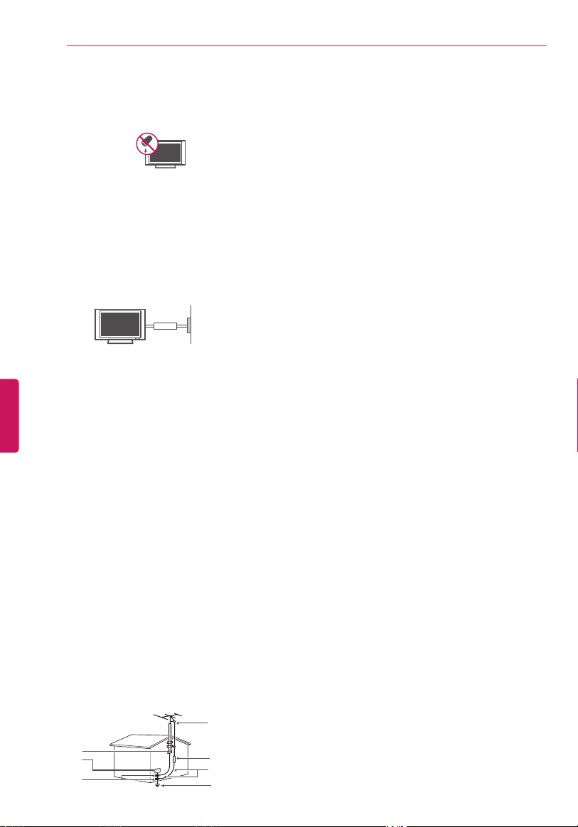
Outdoor Antenna Grounding
(Can differ by country):
If an outdoor antenna is installed, follow the
precautions below. An outdoor antenna system
should not be located in the vicinity of overhead
power lines or other electric light or power circuits,
or where it can come in contact with such power
lines or circuits as death or serious injury can
occur. Be sure the antenna system is grounded to
provide some protection against voltage surges
and built-up static charges. Section 810 of the
National Electrical Code (NEC) in the U.S.A. provides
information with respect to proper grounding of
the mast and supporting structure, grounding
of the lead-in wire to an antenna discharge unit,
size of grounding conductors, location of antenna
discharge unit, connection to grounding electrodes,
and requirements for the grounding electrode.
Antenna grounding according to the National
Electrical Code, ANSI/NFPA 70
Short-circuit
Breaker
Power Supply
Ground Clamp
Grounding Conductor
(NEC Section 810-21)
Antenna Lead in Wire
Electric Service
Equipment
Antenna Discharge Unit
(NEC Section 810-20)
Ground Clamp
Power Service Grounding
Electrode System
(NEC Art 250, Part H)
NEC: National Electrical Code
Cleaning
When cleaning, unplug the power cord and wipe
gently with a soft cloth to prevent scratching. Do
not spray water or other liquids directly on the
TV as electric shock may occur. Do not clean with
chemicals such as alcohol, thinners, or benzene.
Moving
Make sure the product is turned off, unplugged and
all cables have been removed. It may take 2 or more
people to carry larger TVs. Do not press or put stress
on the front panel of the TV.
Ventilation
Install your TV where there is proper ventilation.
Do not install in a confined space such as a
bookcase. Do not cover the product with cloth or
other materials while plugged in. Do not install in
excessively dusty places.
If you smell smoke or other odors coming from
the TV, unplug the power cord and contact an
authorized service center.
Keep the product away from direct sunlight.
Never touch this apparatus or antenna during a
thunder or lightning storm.
When mounting a TV on the wall, make sure not
to install the TV by hanging the power and signal
cables on the back of the TV.
Do not allow an impact shock or any objects to fall
into the product, and do not drop anything onto
the screen.
DISCONNECTING THE DEVICE FROM THE MAIN
POWER
The power plug is the disconnecting device. In
case of an emergency, the Power Plug must remain
readily accessible.
Batteries
Store the accessories (battery, etc.) in a safe location
out of the reach of children.
This apparatus uses batteries. In your community
there might be regulations that require you
to dispose of these batteries properly due to
environmental considerations. Please contact
your local authorities for disposal or recycling
information.
Do not dispose of batteries in a fire.
Do not short circuit, disassemble or allow the
batteries to overheat.
Do not use high voltage electrical equipment
near the TV, (e.g., a bug zapper). This may result in
product malfunction.
Dot Defect
The panel is a high technology product with
resolution of two million to six million pixels.
In a very few cases, you could see fine dots on
the screen while you’re viewing the TV. Those

ENGENGLISH
5
IMPORTANT SAFETY INSTRUCTIONS
dots are deactivated pixels and do not affect the
performance and reliability of the TV.
Generated Sound
Cracking noise A cracking noise that occurs when
watching or turning off the TV is generated by
plastic thermal contraction due to temperature and
humidity. This noise is common for products where
thermal deformation is required.
Electrical circuit humming/panel buzzing A
low level noise is generated from a high-speed
switching circuit, which supplies a large amount of
current to operate a product. It varies depending
upon the product.
This generated sound does not affect the
performance and reliability of the product.
Take care not to touch the ventilation openings.
When watching the TV for a long period, the
ventilation openings may become hot. This does
not affect the performance of the product or cause
defects in the product.
Do not install this product on a wall if it could be
exposed to oil or oil mist. This may damage the
product and cause it to fall.
If the TV feels cold to the touch, there may be a
small flicker when it is turned on. This is normal,
there is nothing wrong with TV. Some minute dot
defects may be visible on the screen, appearing
as tiny red, green, or blue spots. However, they
have no adverse effect on the TV’s performance.
Avoid touching the screen or holding your finger(s)
against it for long periods of time. Doing so may
produce some temporary distortion effects on the
screen.
Displaying a still image for a prolonged period of
time may cause an image sticking. Avoid displaying
a fixed image on the TV screen for a extended
length of time.
FCC Notice
(For USA)
This equipment has been tested and found to comply
with the limits for a Class B digital device, pursuant
to Part 15 of the FCC Rules. These limits are designed
to provide reasonable protection against harmful
interference in a residential installation. This equipment
generates, uses, and can radiate radio frequency energy
and, if not installed and used in accordance with the
instructions, may cause harmful interference to radio
communications. However, there is no guarantee that
interference will not occur in a particular installation.
If this equipment does cause harmful interference to
radio or television reception, which can be determined
by turning the equipment off and on, the user is
encouraged to try to correct the interference by one or
more of the following measures:
- Reorient or relocate the receiving antenna.
- Increase the separation between the equipment
and the receiver.
- Connect the equipment to an outlet on a circuit
different from that to which the receiver is
connected.
- Consult the dealer or an experienced radio/TV
technician for help.
This device complies with part 15 of the FCC Rules.
Operation is subject to the following two conditions:
(1) this device may not cause harmful interference and
(2) this device must accept any interference received,
including interference that may cause undesired
operation of the device.
Any changes or modifications in construction of this
device which are not expressly approved by the party
responsible for compliance could void the user’s
authority to operate the equipment.

ENG
ENGLISH
6
IMPORTANT SAFETY INSTRUCTIONS
FCC Radio Frequency Interference
Requirements (for UNII devices)
High power radars are allocated as primary users
of the 5.25 to 5.35 GHz and 5.65 to 5.85 GHz bands.
These radar stations can cause interference with and/
or damage this device. This device cannot be co-
located with any other transmitter.
FCC RF Radiation Exposure Statement
[For having wireless function (WLAN, Bluetooth,...)]
This equipment complies with FCC radiation exposure
limits set forth for an uncontrolled environment. This
transmitter must not be co-located or operating in
conjunction with any other antenna or transmitter.
This equipment should be installed and operated with
minimum distance 20 cm (7.8 inches) between the
antenna and your body. Users must follow the specific
operating instructions for satisfying RF exposure
compliance.
Industry Canada Statement
(For Canada)
[For having wireless function (WLAN, Bluetooth,...)]
This device complies with RSS-210 of the Industry
Canada Rules. Operation is subject to the following
two conditions:
1. This device may not cause interference and
2. This device must accept any interference, including
interference that may cause undesired operation of
the device.
IC Radiation Exposure Statement
(For Canada)
[For having wireless function (WLAN, Bluetooth,...)]
This equipment complies with IC radiation exposure
limits set forth for an uncontrolled environment. This
equipment should be installed and operated with
minimum distance 20 cm (7.8 inches) between the
antenna and your body.
NOTE: THE MANUFACTURER IS NOT RESPONSIBLE
FOR ANY RADIO OR TV INTERFERENCE CAUSED
BY UNAUTHORIZED MODIFICATIONS TO THIS
EQUIPMENT. SUCH MODIFICATIONS COULD VOID THE
USER’S AUTHORITY TO OPERATE THE EQUIPMENT.
WARNING
(For Canada)
[For product having the wireless function using
5 GHz frequency bands]
The device for operation in the band 5150–
5250 MHz is only for indoor use to reduce
the potential for harmful interference to co-
channel mobile satellite systems;
The maximum antenna gain permitted for
devices in the bands 5250–5350 MHz and
5470–5725 MHz shall comply with the EIRP
limit; and
The maximum antenna gain permitted for
devices in the band 5725–5825 MHz shall
comply with the EIRP limits specified for point-
to-point and non point-to-point operation as
appropriate.
High-power radars are allocated as primary
users (i.e., priority users) of the bands 5250–
5350 MHz and 5650–5850 MHz and that
these radars could cause interference and/or
damage to LE-LAN devices.
Note to Cable/TV Installer
(For USA and Canada)
This reminder is provided to call the CATV system
installer’s attention to Article 820-40 of the National
Electric Code (U.S.A.). The code provides guidelines
for proper grounding and, in particular, specifies
that the cable ground shall be connected to the
grounding system of the building, as close to the
point of the cable entry as practical.
LG Recycling Policy
(For USA)
LG Electronics offers a customized e-waste takeback
and recycling service that meets local needs and
requirements in the countries where e-waste
regulations are in place, and also provides product and
packaging take-back and recycling service voluntarily
in some countries. LG Electronics evaluates products’
recyclability at the design step using LG’s recyclability
evaluation tool, with the goal of improving recyclability
where practicable. Through these activities, LG seeks
to contribute to conserving natural resources and
protecting the environment.
For more information about the LG Recycling Policy,
please visit our global site at
http://www.lg.com/global/
sustainability/environment/take-back-recycling

ENGENGLISH
7
IMPORTANT SAFETY INSTRUCTIONS
Viewing 3D Imaging
WARNING
Viewing Environment
Viewing Time
-
When watching 3D contents, take five- to
fifteen-minute breaks every hour. Viewing 3D
contents for a long period of time may cause
headache, dizziness, fatigue, or eye strain.
Those that have a photosensitive seizure or
chronic illness
Some users may experience a seizure or other
abnormal symptoms when they are exposed
to a flashing light or particular pattern from
3D contents.
Do not watch 3D videos if you feel nausea, are
pregnant and/ or have a chronic illness such
as epilepsy, cardiac disorder, or blood pressure
disease, etc.
3D Contents are not recommended for those
who suffer from stereo blindness or stereo
anomaly. Double images or discomfort in
viewing may be experienced.
If you have strabismus (cross-eyed), amblyopia
(weak eyesight), or astigmatism, you may have
trouble sensing depth and easily feel fatigue
due to double images. It is advised to take
frequent breaks than the average adult.
If your eyesight varies between your right
and left eye, correct your eyesight prior to
watching 3D contents.
Symptoms which require discontinuation or
refraining from watching 3D contents
Do not watch 3D contents when you feel
fatigue from lack of sleep, overwork or
drinking.
When these symptoms are experienced, stop
using/watching 3D contents and get enough
rest until the symptom subsides.
- Consult your doctor when the symptoms
persist. Symptoms may include headache,
eyeball pain, dizziness, nausea, palpitation,
blurriness, discomfort, double image,
eyestrain, or fatigue.
CAUTION
Viewing Environment
Viewing Distance
-
Maintain a distance of at least twice the screen
diagonal length when watching 3D contents.
If you feel discomfort in viewing 3D contents,
move further away from the TV.
Viewing Age
Infants / Children
- Usage/ Viewing 3D contents for children under
the age of 5 is not recommended.
- Children under the age of 10 may overreact
and become overly excited because their vision
is in development, for example, trying to touch
the screen or trying to jump into it. Special
monitoring and extra attention is required for
children watching 3D contents.
- Children have greater binocular disparity of 3D
presentations than adults because the distance
between the eyes is shorter than one of adults.
Therefore they will perceive more stereoscopic
depth compared to adults for the same 3D
image.
Teenagers
- Teenagers may be stimulated by light coming
from 3D videos. Advise them not to watch 3D
videos for a long time when they are tired.
Elderly
- The elderly may perceive less of a 3D effect
than the youth. Do not sit closer to the TV
than the recommended distance.
Cautions when using the 3D glasses
Make sure to use LG 3D glasses. Otherwise,
you may not be able to view 3D videos
properly.
Do not use 3D glasses instead of your normal
glasses, sunglasses, or protective goggles.
Using modified 3D glasses may cause eye
strain or image distortion.
Do not keep your 3D glasses in extremely high
or low temperatures. It will cause deformation.
The 3D glasses are fragile and are easily
scratched. Always use a soft, clean piece of cloth
when wiping the lenses. Do not scratch the
lenses of the 3D glasses with sharp objects or
clean/wipe them with chemicals.

ENG
ENGLISH
8
LICENSES / OPEN SOURCE SOFTWARE NOTICE INFORMATION
LICENSES
Supported licenses may differ by model.
For more information about licenses, visit
www.lg.com
.
OPEN SOURCE SOFTWARE NOTICE INFORMATION
To obtain the source code under GPL, LGPL, MPL, and other open source licenses, that is contained in this
product, please visit
http://opensource.lge.com
.
In addition to the source code, all referred license terms, warranty disclaimers and copyright notices are
available for download.
LG Electronics will also provide open source code to you on CD-ROM for a charge covering the cost of
performing such distribution (such as the cost of media, shipping, and handling) upon email request to
. This offer is valid for three (3) years from the date on which you purchased the
product.

ENGENGLISH
9
TABLE OF CONTENTS
2 IMPORTANT SAFETY
INSTRUCTIONS
5 - FCC Notice
6 - Industry Canada Statement
6 - IC Radiation Exposure Statement
6 - Note to Cable/TV Installer
6 - LG Recycling Policy
7 Viewing 3D Imaging
8 LICENSES
8 OPEN SOURCE SOFTWARE NOTICE
INFORMATION
9 TABLE OF CONTENTS
10 INSTALLATION PROCEDURE
10 ASSEMBLING AND PREPARING
10 Unpacking
12 Optional Extras
13 Parts and Buttons
14 - Using the Joystick button
15 Lifting and Moving the TV
16 Setting Up the TV
16 - Attaching the Stand
20 - Mounting on a Table
21 - Tidying Cables
22 - Mounting on a Wall
23 MAKING CONNECTIONS
23 Connecting to an Antenna or Cable
24 Connecting to a HD receiver, DVD Player, or
VCR
24 - HDMI Connection
25 - DVI to HDMI Connection
26 - Component Connection
27 - Composite Connection
28 Connecting to a PC
29 - HDMI Connection or DVI to HDMI
Connection
30 Connecting to an Audio System
30 - Digital Optical Audio Connection
31 Connecting Headphones
32 Connecting a USB Drive
33 MAGIC REMOTE FUNCTIONS
34 Registering Magic Remote
34 How to Use Magic Remote
34 Precautions to Take
34 USING THE USER GUIDE
35 SPECIFICATIONS
37 MAINTENANCE
37 Cleaning Your TV
37 - Screen, Frame, Cabinet, and Stand
37 - Power Cord
37 TROUBLESHOOTING
TABLE OF CONTENTS
Image shown may differ from your TV.
Your TV’s OSD (On Screen Display) may differ
slightly from that shown in this manual.
The available menus and options may differ
from the input source or product model that
you are using.
New features may be added to this TV in the
future.
NOTE
ENG
ENGLISH
10
INSTALLATION PROCEDURE / ASSEMBLING AND PREPARING
INSTALLATION PROCEDURE
1
Open the package and make sure all the accessories are included.
2
Attach the stand to the TV set.
3
Connect an external device to the TV set.
4
Make sure the network connection is available.
You can use the TV network functions only when the network connection is made.
* When the TV is turned on for the first time after being shipped from the factory, initialization of the TV may
take approximately one minute.
ASSEMBLING AND PREPARING
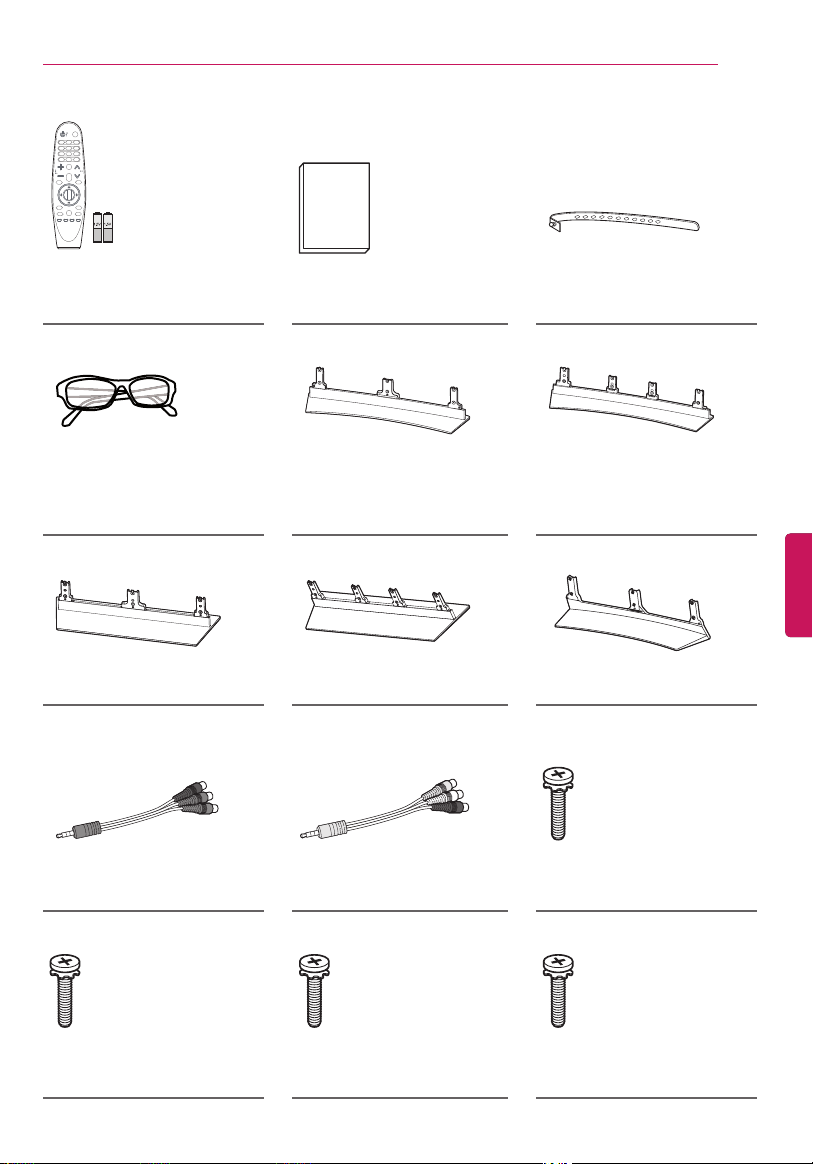
Unpacking
Check your product box for the following items. If there are any missing accessories, contact the local dealer
where you purchased your product. The illustrations in this manual may differ from the actual product and
item.
Do not use any unapproved items to ensure the safety and product life span.
Any damages or injuries by using unapproved items are not covered by the warranty.
In case of some model, the thin film on screen is a part of the TV, So don’t take it off.
CAUTION
The items supplied with your product may vary depending upon the model.
Product specifications or contents of this manual may be changed without prior notice due to
upgrade of product functions.
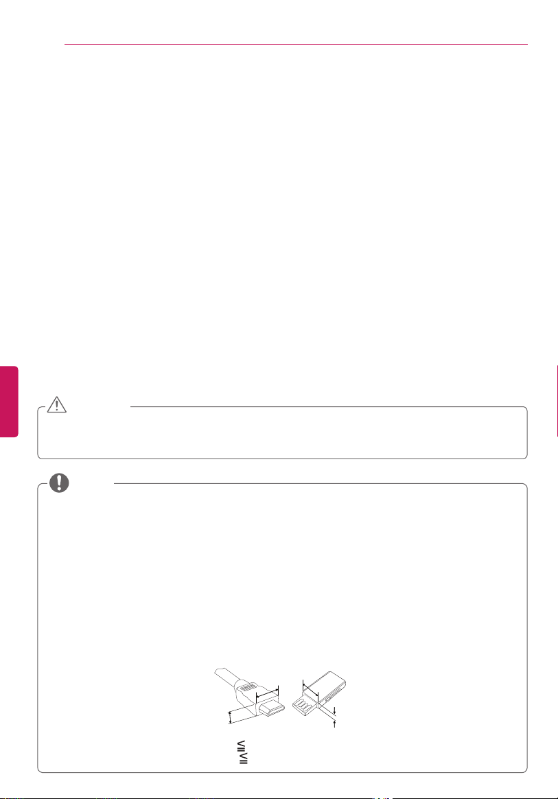
For an optimal connection, HDMI cables and USB devices should have bezels less than 10 mm (0.39
inches) thick and 18 mm (0.7 inches) width.
Use an extension cable that supports USB 2.0 if the USB cable or USB FLASH DRIVE does not fit into
your TV’s USB port.
Use a certified cable with the HDMI logo attached. If you do not use a certified HDMI cable, the screen
may not display or a connection error may occur.
Recommended HDMI cable types (3 m or less)
- High-Speed HDMI
®
/
TM
cable
- High-Speed HDMI
®
/
TM
cable with Ethernet
B
A
A
B
*A 10 mm (0.39 inches)
*B 18 mm (0.7 inches)
NOTE
ENGENGLISH
11
ASSEMBLING AND PREPARING
P
Magic Remote,
Batteries (AA)
(See page 33.)
Owner’s Manual Cable Holder
(See page 21.)
(For 55EG9600) (For 65EG9600)
Cinema 3D Glasses
The number of 3D glasses
may differ depending upon
the model or country.
Stand Base
(See page 16, 17.)
Stand Base
(See page 17, 18.)
(For 55EF9500) (For 65EF9500)
(For 55EG9200)
Stand Base
(See page 18, 19.)
Stand Base
(See page 19, 20.)
Stand Base
(See page 16, 17.)
(For 55EG9600, 55EG9200)
Component Video Cable
(See page 26.)
Composite Video Cable
(See page 26, 27.)
Stand Screws
5 EA, M4 x L20
(See page 17.)
(For 65EG9600) (For 55EF9500) (For 65EF9500)
Stand Screws
8 EA, M4 x L20
(See page 18.)
Stand Screws
5 EA, M4 x L14
(See page 19.)
Stand Screws
8 EA, M4 x L14
(See page 20.)

ENG
ENGLISH
12
ASSEMBLING AND PREPARING
Optional Extras
Optional extras can be changed or modified for quality improvement without any notification.
Contact your dealer for buying these items.
These devices work only with certain models.
The model name or design may be changed manufacturer’s circumstances or policies.
AN-MR6**
Magic Remote
AG-F***
Cinema 3D Glasses
AN-VC550
Smart Camera
AG-F***DP
Dual Play Glasses
LG Audio Device
ENGENGLISH
13
ASSEMBLING AND PREPARING
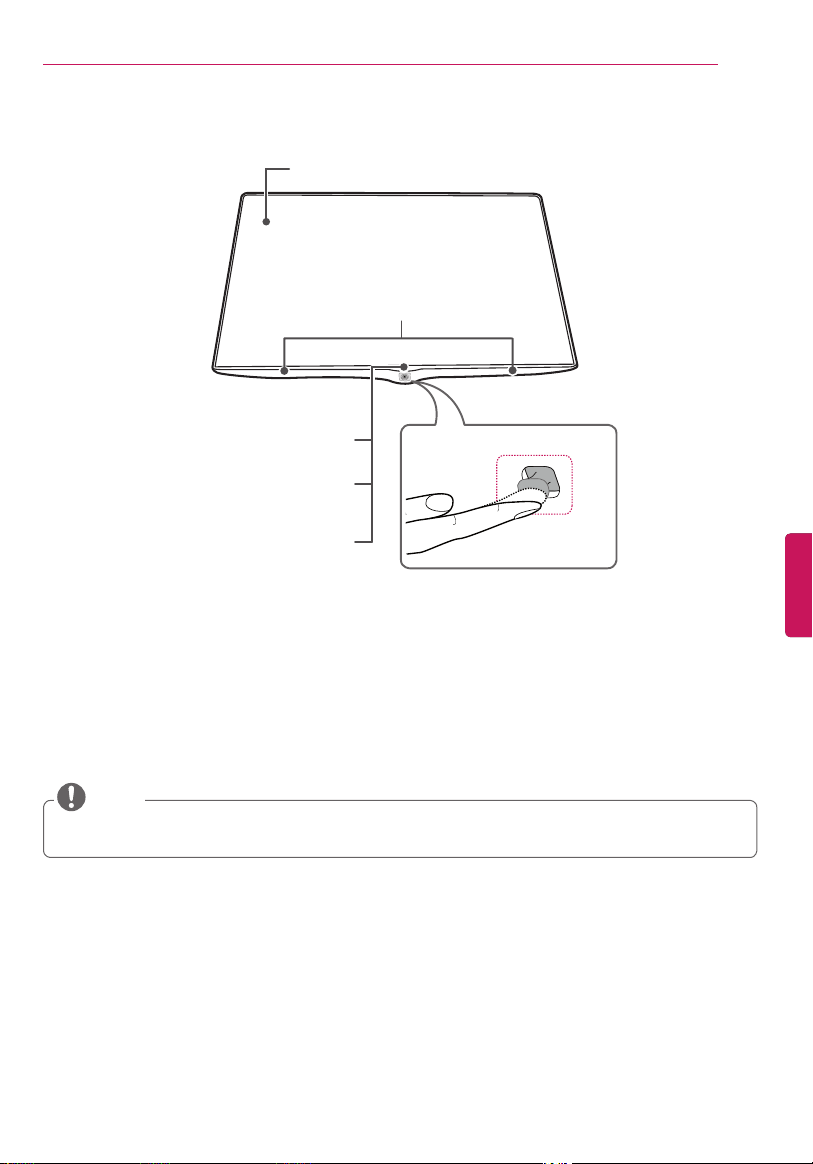
Parts and Buttons
1
Intelligent sensor - Adjusts the image quality and brightness based on the surrounding environment.
2
Joystick button is located below the screen of TV.
LG Logo Light
(For EG9600, EF9500 series)
Power Indicator
(For EG9200 series)
Screen
Speakers
Joystick button
2
You can set the LG Logo Light to be on or off by selecting GENERAL in the main menus.
(Depending upon model)
NOTE
Remote Control Sensor
Intelligent Sensor
1
(Depending upon model)
ENG
ENGLISH
14
ASSEMBLING AND PREPARING
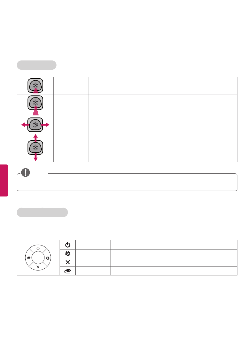
Using the Joystick button
You can operate the TV by pressing the button or moving the joystick left, right, up, or down.
Basic functions
Power On
When the TV is turned off, place your finger on the joystick button,
press it once, and release it.
Power Off
When the TV is turned on, place your finger on the joystick button,
press it once for a few seconds, and release it. All running apps will
close.
Volume
Control
Place your finger on the joystick button and move it left or right to
adjust the volume level.
Channels
Control
Place your finger on the joystick button and move it up or down to
adjust the channels.
Move the joystick button up, down, left, or right. Be careful not to press it. If you press it first, you may
not be able to adjust the volume or scroll through the channels.
NOTE
Adjusting the menu
When the TV is turned on, press the joystick button one time.
You can adjust the menu items moving the joystick button up, down, left, or right.
POWER OFF Turns the power off.
SETTINGS Accesses the quick settings.
CLOSE Clears on-screen displays and returns to TV viewing.
INPUTS Changes the input source.
ENGENGLISH
15
ASSEMBLING AND PREPARING
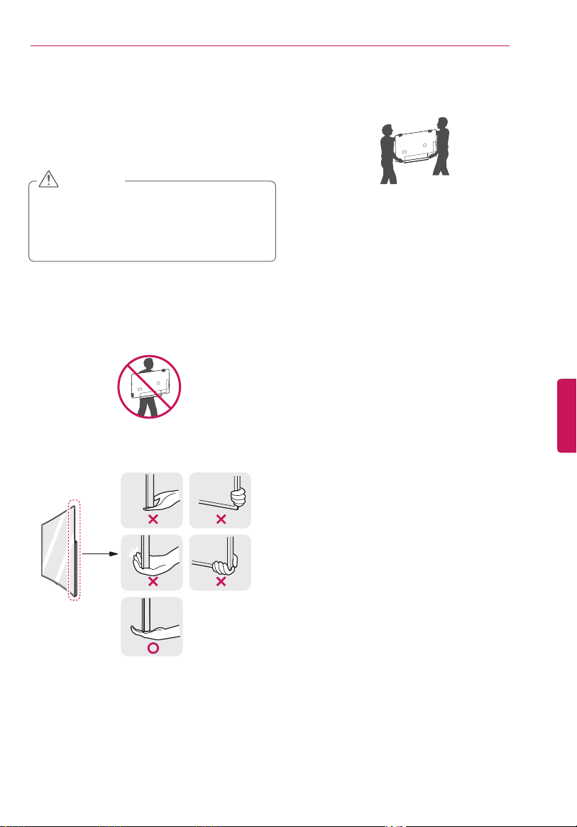
Lifting and Moving the TV
When moving or lifting the TV, read the following to
prevent the TV from being scratched or damaged
and for safe transportation regardless of its type and
size.
Avoid touching the screen at all times, as this
may result in damage to the screen.
Do not place the product on the floor with its
front facing down without padding. Failure to
do so may result in damage to the screen.
CAUTION
Move the TV in the box or packing material that
the TV originally came in.
Before moving or lifting the TV, disconnect the
power cord and all cables.
When holding the TV, the screen should face
away from you to avoid damage.
Hold the top and bottom of the TV frame
firmly. Make sure not to hold the transparent
part, speaker, or speaker grill area.
Use at least two people to move a large TV.
When transporting the TV by hand, hold the
TV as shown in the following illustration.
When handling the TV, be careful not to
damage the protruding joystick button.
When transporting the TV, do not expose the
TV to jolts or excessive vibration.
When transporting the TV, keep the TV
upright; never turn the TV on its side or tilt
towards the left or right.
Do not apply excessive pressure to cause
flexing / bending of frame chassis as it may
damage screen.
Be sure to keep your TV upright instead of
laying or tilting it while moving the TV.
ENG
ENGLISH
16
ASSEMBLING AND PREPARING
1
2
Setting Up the TV
You can mount your TV to a wall or attach the stand if you wish to place the TV on an entertainment center
or other furniture.
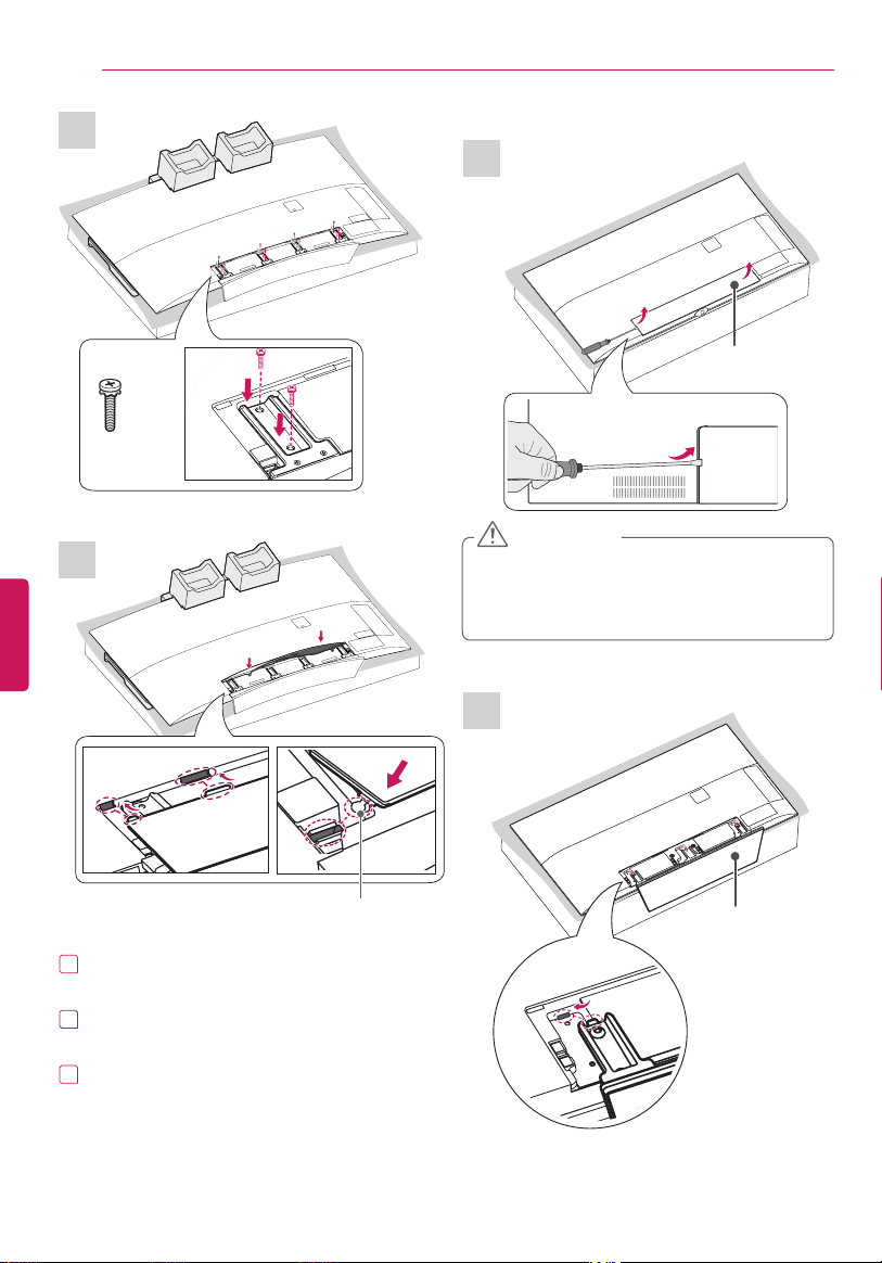
Attaching the Stand
If you are not mounting the TV to a wall, use the following instructions to attach the stand.
Make sure that the screws are fastened tightly. (If they are not fastened securely enough, the TV may
tilt forward after being installed.)
Do not tighten the screws with too much force; otherwise they may be damaged and come loose later.
CAUTION
Remove the stand before installing the TV on a wall mount by performing the stand attachment in reverse.
NOTE
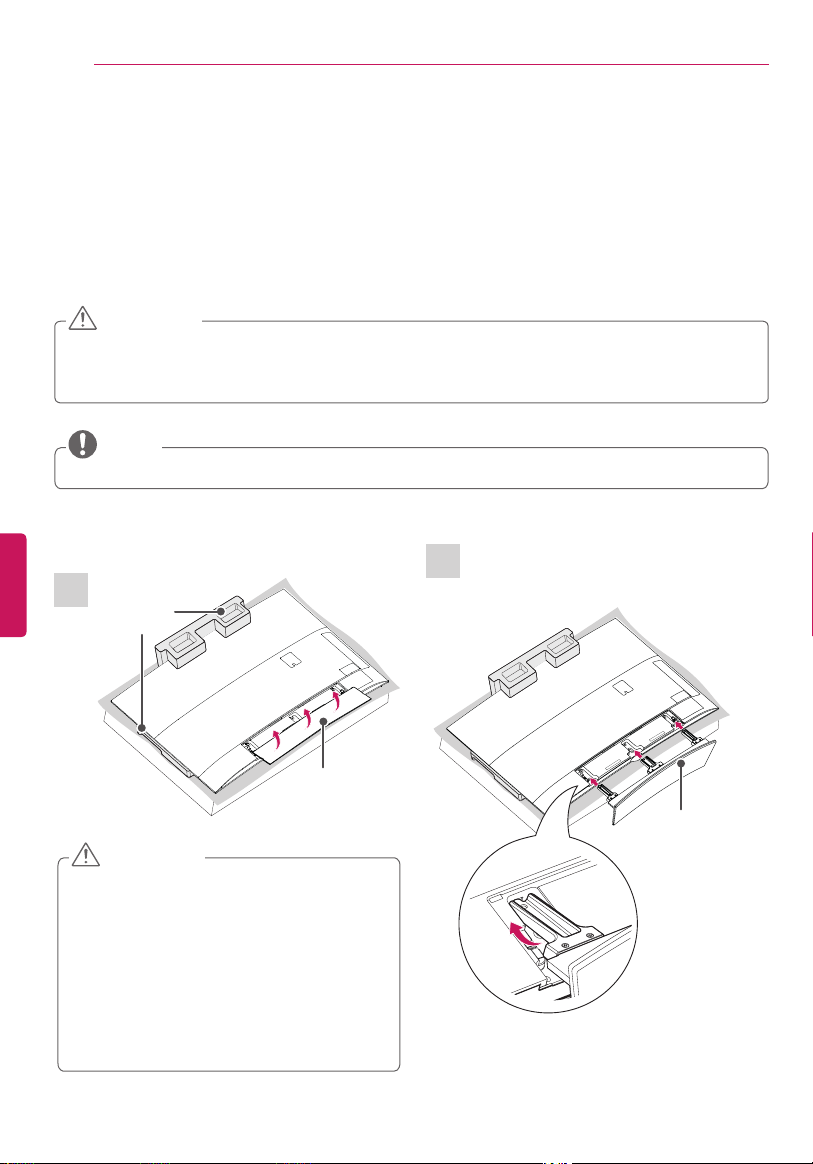
Stand Cover
Stand Base
(For 55EG9600, 55EG9200)
Packing
Brace
When assembling the stand, lay the packing
brace on a table or product box and then
place the TV with its screen facing down
on the packing brace. Be sure to protect
the screen from scratches. When there is no
packing brace provided, make sure that you
place the screen on soft clothing or a cushion.
Do not place the TV without the stand
attached into its upright position. The
protruding Joystick Button may be damaged.
CAUTION
ENGENGLISH
17
ASSEMBLING AND PREPARING
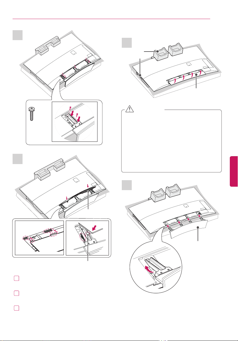
4
3
1
2
Stand Base
Cover Holder
(For 65EG9600)
5 EA
M4 x L20
Stand Cover
Stand Cover
Packing
Brace
1
Insert the protruding parts of the stand cover
into the holes.
2
Insert the cover holder of the stand cover into
the holes until it clicks.
3
Press the stand cover gently so that the non-
woven fabric inside is attached tightly.
When assembling the stand, lay the packing
brace on a table or product box and then
place the TV with its screen facing down
on the packing brace. Be sure to protect
the screen from scratches. When there is no
packing brace provided, make sure that you
place the screen on soft clothing or a cushion.
Do not place the TV without the stand
attached into its upright position. The
protruding Joystick Button may be damaged.
CAUTION
ENG
ENGLISH
18
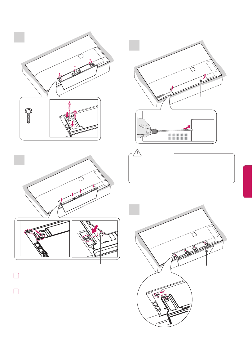
ASSEMBLING AND PREPARING
4
Cover Holder
3
8 EA
M4 x L20
1
Insert the protruding parts of the stand cover
into the holes.
2
Insert the cover holder of the stand cover into
the holes until it clicks.
3
Press the stand cover gently so that the non-
woven fabric inside is attached tightly.
1
2
Stand Base
(For 55EF9500)
Stand Cover
Do not place the TV without the stand
attached into its upright position. The
protruding Joystick Button may be damaged.
Use a flat tool to remove the stand cover.
CAUTION
ENGENGLISH
19
ASSEMBLING AND PREPARING
1
Insert the protruding parts of the stand cover
into the holes.
2
Insert the cover holder of the stand cover into
the holes until it clicks.
1
2
Stand Base
(For 65EF9500)
Stand Cover
Do not place the TV without the stand
attached into its upright position. The
protruding Joystick Button may be damaged.
Use a flat tool to remove the stand cover.
CAUTION
4
3
5 EA
M4 x L14
Cover Holder
ENG
ENGLISH
20
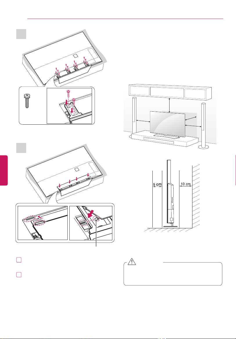
ASSEMBLING AND PREPARING
Mounting on a Table
(Image shown may differ from your TV.)
1
Lift and tilt the TV into its upright position on a
table.
- Leave a 10 cm (4 inches) (minimum) space
from the wall for proper ventilation.
10 cm
10 cm
10 cm
10 cm
(4 inches)
10 cm
10 cm
10 cm
10 cm
2
Connect the power cord to a wall outlet.
Do not place the TV near or on sources
of heat, as this may result in fire or other
damage.
CAUTION
4
3
8 EA
M4 x L14
1
Insert the protruding parts of the stand cover
into the holes.
2
Insert the cover holder of the stand cover into
the holes until it clicks.
Cover Holder
ENGENGLISH
21
ASSEMBLING AND PREPARING
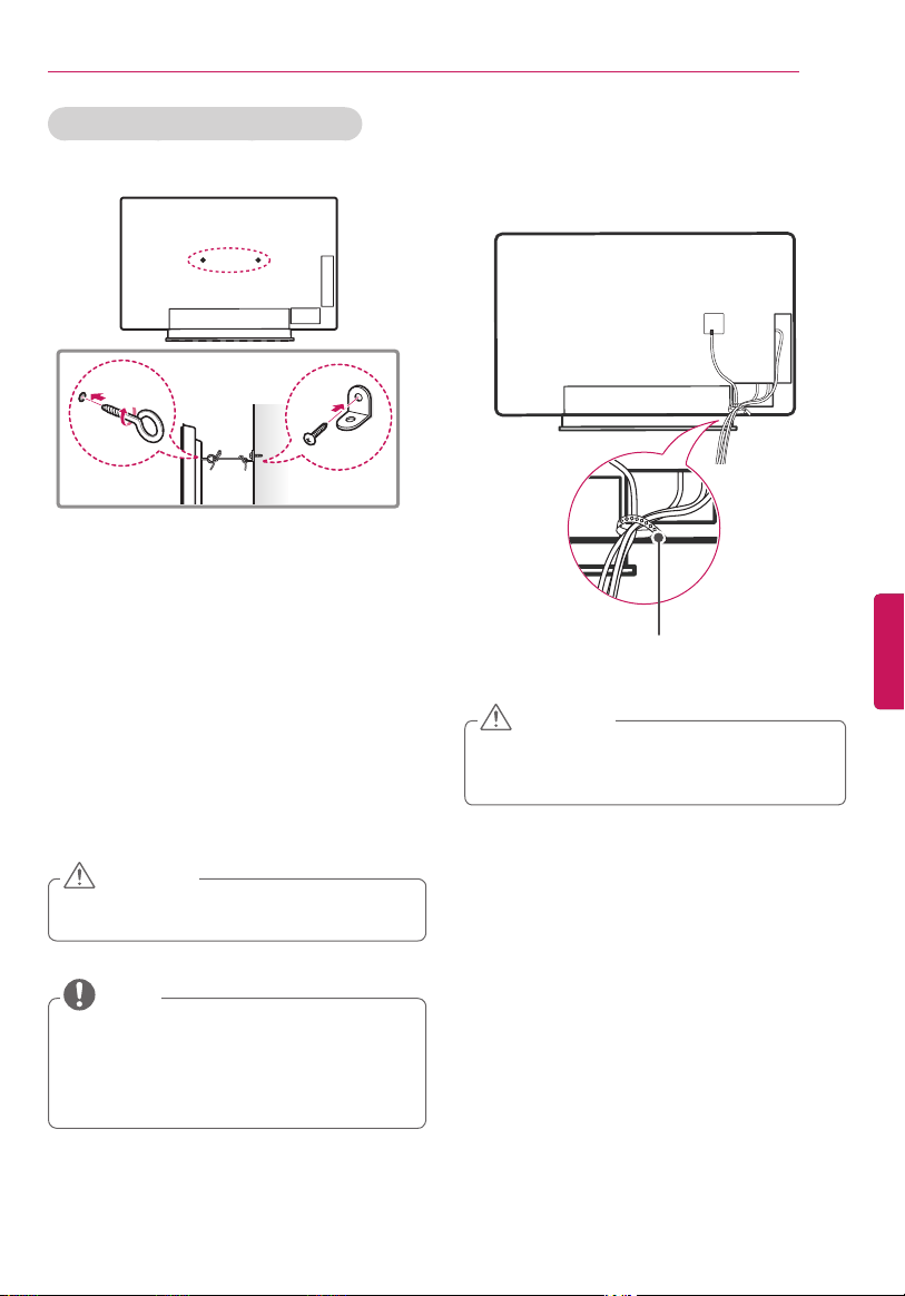
Securing the TV to a wall (optional)
(Depending upon model)
1
Insert and tighten the eye-bolts, or TV brackets
and bolts on the back of the TV.
- If there are bolts inserted at the eye-bolts
position, remove the bolts first.
2
Mount the wall brackets with the bolts to
the
wall.
Match the location of the wall bracket and the
eye-bolts on the rear of the TV.
3
Connect the eye-bolts and wall brackets
tightly
with a sturdy rope or cable.
Make sure to keep the rope parallel to the flat
surface.
Make sure that children do not climb on or
hang on the TV.
CAUTION
Use a platform or cabinet that is strong and
large enough to support the TV securely.
Brackets, bolts, and ropes are optional. You
can obtain additional accessories from your
local dealer.
NOTE
Tidying Cables
Gather and bind the cables with the cable holder.
Cable Holder
Do not move the TV by holding the cable
holder, as the cable holder may break, and
injuries and damage to the TV may occur.
CAUTION
ENG
ENGLISH
22
ASSEMBLING AND PREPARING
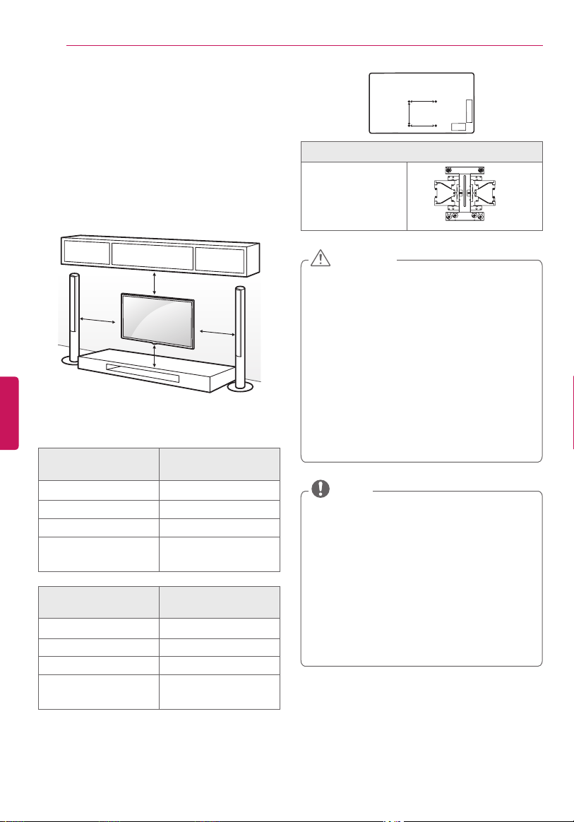
Mounting on a Wall
An optional wall mount can be used with your LG
Television. Consult with your local dealer for a wall
mount used by your TV model. Carefully attach the
wall mount bracket at the rear of the TV. Install the
wall mount bracket on a solid wall perpendicular
to the floor. If you are attaching the TV to other
building materials, please contact qualified
personnel to install the wall mount. Detailed
instructions will be included with the wall mount.
10 cm
10 cm
10 cm
10 cm
(4 inches)
Make sure to use screws and wall mounts that meet
the standard. Standard dimensions for the wall
mount kits are described in the following table.
Model 55EG9600
55EG9200
A x B x C 200 x 340 x 195
Standard screw M6
Number of screws 4
Wall mount bracket
(optional)
OTW150
Model 65EG9600
55/65EF9500
A x B x C 200 x 330 x 120
Standard screw M6
Number of screws 4
Wall mount bracket
(optional)
OTW150
Disconnect the power first, and then move or
install the TV. Otherwise electric shock may
occur.
If you install the TV on a ceiling or slanted
wall, it may fall and result in severe injury.
Use an authorized LG wall mount and contact
the local dealer or qualified personnel.
Do not overtighten the screws as this may
cause damage to the TV and void your
warranty.
Use the screws and wall mounts that meet
the standard. Any damages or injuries by
misuse or using an improper accessory are
not covered by the warranty.
CAUTION
Use the screws that are listed on the standard
screw specifications.
The wall mount kit includes an installation
manual and necessary parts.
The wall mount bracket is optional. You can
obtain additional accessories from your local
dealer.
The length of screws may differ depending upon
the wall mount. Make sure to use the proper
length.
For more information, refer to the manual
supplied with the wall mount.
NOTE
A
B
C
Wall mount bracket (optional)
OTW150

ENGENGLISH
23
MAKING CONNECTIONS
MAKING CONNECTIONS
You can connect various external devices to the TV. Supported external devices are: HD receivers, DVD
players, VCRs, audio systems, USB storage devices, PC, gaming devices, and other external devices. For more
information on external device’s connection, refer to the manual provided with each device.
If you record a TV program on a DVD recorder or VCR, make sure to connect the TV signal input cable
to the TV through a DVD recorder or VCR. For more information of recording, refer to the manual
provided with the connected device.
The external device connections shown may differ slightly from illustrations in this manual.
Connect external devices to the TV regardless of the order of the TV port.
If you connect a gaming device to the TV, use the cable supplied with the gaming device.
Refer to the external equipment’s manual for operating instructions.
(Smart TV Only) The TV may be capable of operating without a set-top from a multichannel video
programming distributor (MVPD).
NOTE
Connecting to an Antenna or Cable
Connect an antenna, cable, or cable box to watch TV while referring to the following. The illustrations may
differ from the actual items and a RF cable is optional.
Make sure not to bend the copper wire of the
RF cable.
Copper wire
Complete all connections between devices,
and then connect the power cord to the
power outlet to prevent damage to your TV.
CAUTION
Antena VHF
Antena UHF
Antenna
Coaxial (75Ω)
Terminal
(*Not Provided)
Use a signal splitter to use more than 2 TVs.
DTV Audio Supported Codec: MPEG, Dolby
Digital.
Direct ULTRA HD broadcast is unavailable in
areas without a ULTRA HD signal.
This TV cannot receive ULTRA HD (3840 x
2160 pixels) broadcasts directly because the
related standards have not been confirmed.
NOTE
ENG
ENGLISH
24
MAKING CONNECTIONS
Connecting to a HD receiver, DVD Player, or VCR
Connect a HD receiver, DVD Player, or VCR to the TV and select an appropriate input mode.
HDMI specifications may be different for each input port, so make sure to check the device
specifications before connecting.
Contact customer service for more information on the HDMI specifications of each input port.
If the device connected to Input Port also supports ULTRA HD Deep Color, your picture may be clearer.
However, if the device doesn’t support it, it may not work properly. In that case, connect the device to
a different HDMI port or change the TV’s ULTRA HD Deep Color setting to Off.
- This feature is available on certain models which are supported ULTRA HD Deep Color only.
(Home) (Settings) (Advanced) Picture HDMI ULTRA HD Deep Color
- On Support 4 K @ 60 Hz (4:4:4, 4:2:2, 4:2:0)
- Off Support 4 K @ 60 Hz (4:2:0)
NOTE
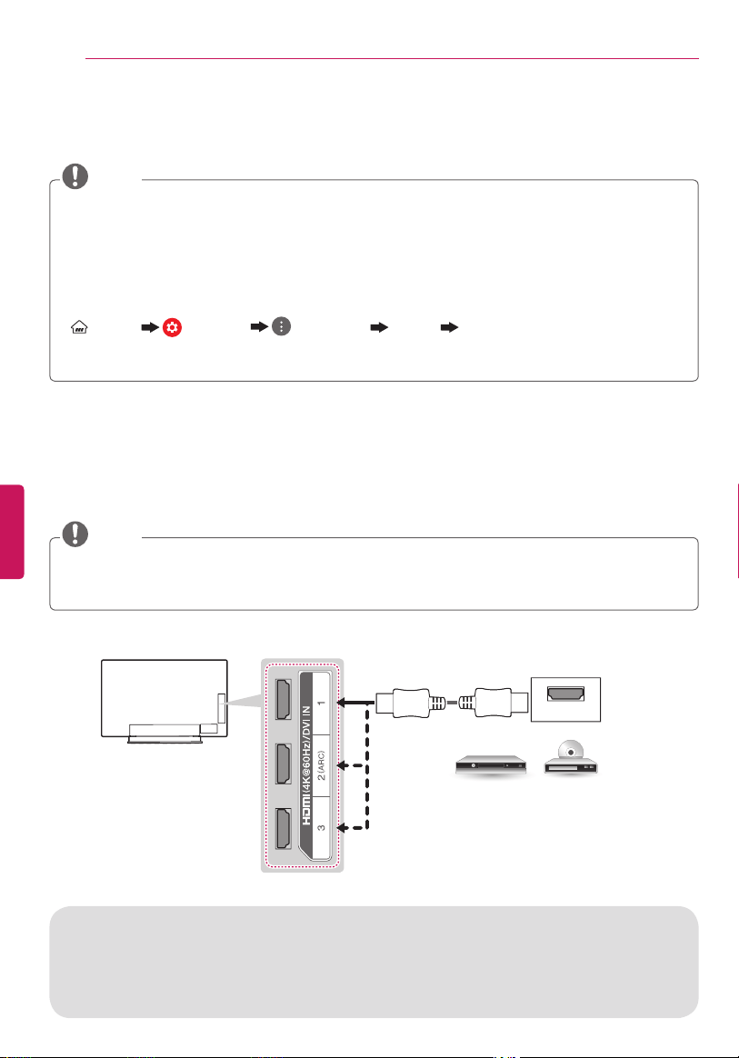
HDMI Connection
HDMI is the best way to connect a device.
Transmits the digital video and audio signals from an external device to the TV. Connect the external device
and the TV with the HDMI cable as shown in the following illustration.
Use the latest High Speed HDMI™ Cable that supports CEC (Customer Electronics Control) function.
High Speed HDMI™ Cables are tested to carry an HD signal up to 1080p and higher.
HDMI Audio Supported Format: PCM (32 kHz / 44.1 kHz / 48 kHz / 96 kHz / 192 kHz)
NOTE
HDMI
DVD / Blu-Ray / HD Cable Box / HD STB
(*Not Provided)
ARC (Audio Return Channel)
When connected with a high-speed HDMI cable, digital audio can be sent to a compatible device
without an additional optical audio cable.
ARC is only supported on the HDMI (4 K @ 60 Hz) / DVI IN 2 (ARC) port. An external audio device that
supports ARC should be connected to HDMI (4 K @ 60 Hz) / DVI IN 2 (ARC) if you wish to use ARC.
ENGENGLISH
25
MAKING CONNECTIONS
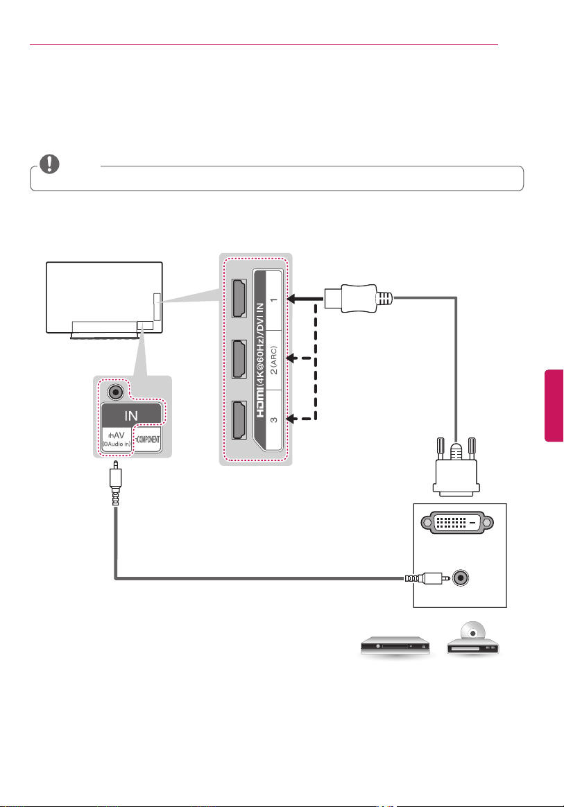
AUDIO OUT
DVI OUT
DVI to HDMI Connection
Transmits the digital video signal from an external device to the TV. Connect the external device and the
TV with the DVI-HDMI cable as shown in the following illustration. To transmit an audio signal, connect an
audio cable.
When using the HDMI/DVI cable, Single link is only supported.
NOTE
(*Not Provided)
(*Not Provided)
DVD / Blu-Ray / HD Cable Box
ENG
ENGLISH
26
MAKING CONNECTIONS
VIDEO
AUDIO
L R
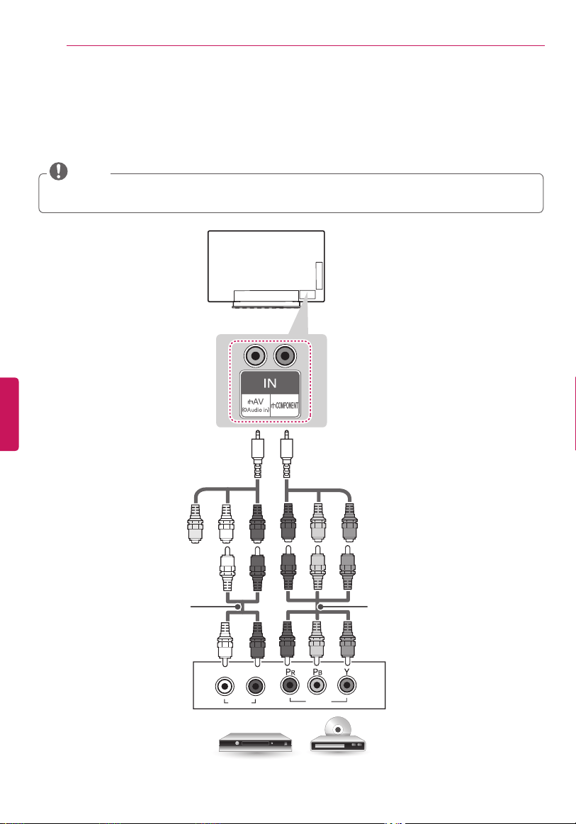
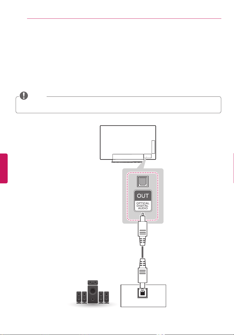
Component Connection
Transmits analog video and audio signals from an external device to the TV. Connect the external device
and the TV with a component cable as shown in the following illustration.
If cables are installed incorrectly, it could cause the image to display in black and white or with distorted color.
Check to ensure the cables are matched with the corresponding color connection.
NOTE
DVD / Blu-Ray / HD Cable Box
YELLOW
YELLOW
WHITE
RED
RED
BLUE
GREEN
WHITE
RED
RED
BLUE
GREEN
WHITE
RED
RED
BLUE
GREEN
(Use the composite video
cable provided.)
GREEN
(Use the component video
cable provided.)
(*Not Provided)(*Not Provided)
ENGENGLISH
27
MAKING CONNECTIONS
VIDEO
MONO
( )
AUDIOLR
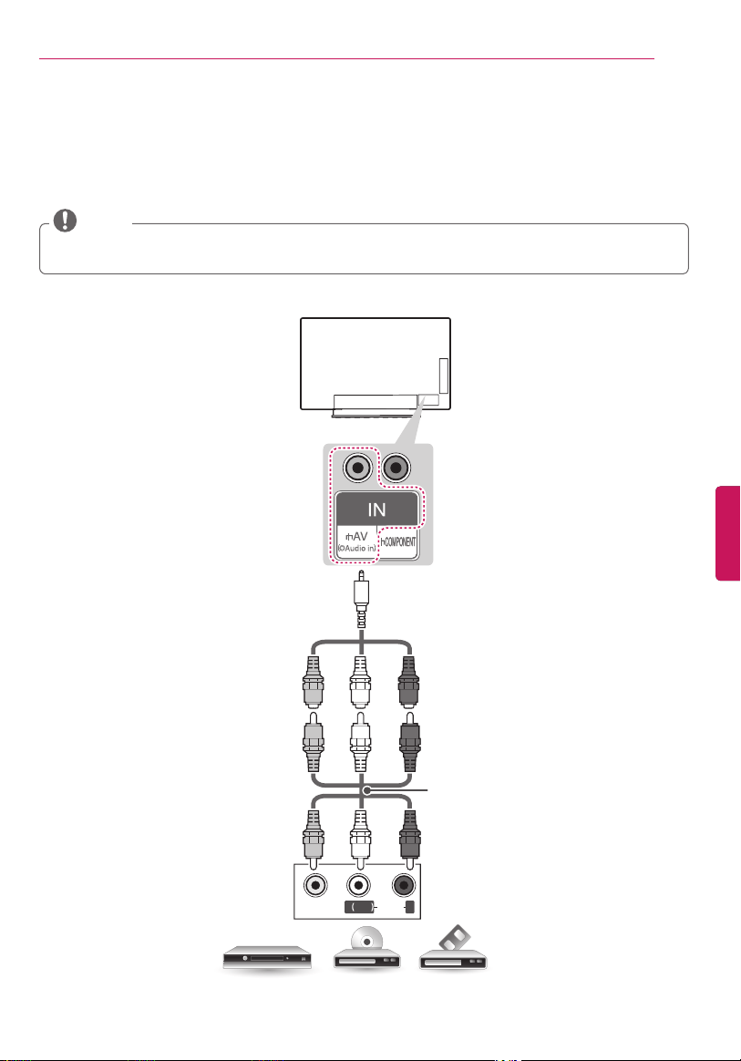
Composite Connection
Transmits analog video and audio signals from an external device to the TV. Connect the external device
and the TV with the composite cable as shown in the following illustration.
If you have a mono VCR, connect the audio cable from the VCR to the AUDIO L/MONO jack of the TV.
Check to ensure the cables are matched with the corresponding color connection.
NOTE
VCR / DVD / Blu-Ray / HD Cable Box
YELLOW
WHITE
RED
WHITE
YELLOW
RED
WHITE
YELLOW
RED
YELLOW
(Use the composite video cable
provided.)
(*Not Provided)
ENG
ENGLISH
28
MAKING CONNECTIONS
Connecting to a PC
Use an HDMI connection for the best image quality.
Depending upon the graphics card, DOS mode video may not work if a HDMI to DVI Cable is in use.
In PC mode, there may be noise associated with the resolution, vertical pattern, contrast or brightness. If
noise is present, change the PC output to another resolution, change the refresh rate to another rate or
adjust the brightness and contrast on the PICTURE menu until the picture is clear.
The synchronization input form for Horizontal and Vertical frequencies is separate.
Depending upon the graphics card, some resolution settings may not allow the image to be positioned on
the screen properly.
If you are using DVI out from a PC, you have to connect analog audio separately. Refer to the instructions on
the next page.
When using the HDMI/DVI cable, Single link is only supported.
If Ultra HD content is played on your PC, video or audio may become disrupted intermittently depending
upon your PC’s performance.
HDMI specifications may be different for each input port, so make sure to check the device
specifications before connecting.
Contact customer service for more information on the HDMI specifications of each input port.
If the device connected to Input Port also supports ULTRA HD Deep Color, your picture may be clearer.
However, if the device doesn’t support it, it may not work properly. In that case, connect the device to
a different HDMI port or change the TV’s ULTRA HD Deep Color setting to Off.
- This feature is available on certain models which are supported ULTRA HD Deep Color only.
(Home) (Settings) (Advanced) Picture HDMI ULTRA HD Deep Color
- On Support 4 K @ 60 Hz (4:4:4, 4:2:2, 4:2:0)
- Off Support 4 K @ 60 Hz (4:2:0)
With the HDMI cable, connect the HDMI (4 K @ 60 Hz) / DVI IN 1 port of your TV to the HDMI output
port of your PC. Then, the TV will output video and audio together.
NOTE
ENGENGLISH
29
MAKING CONNECTIONS
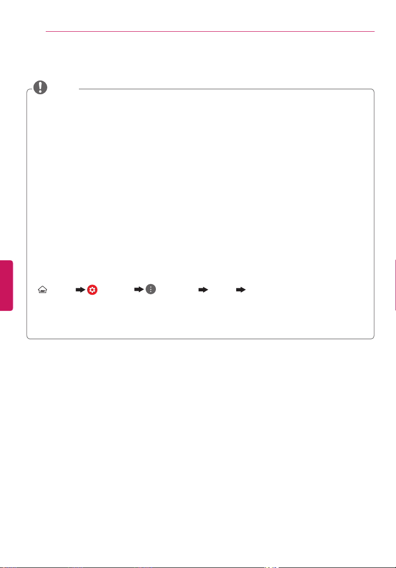
Method B DVI to HDMI Connection
AUDIO OUT
DVI OUT
(*Not Provided)
PC
(*Not Provided)
HDMI Connection or DVI to HDMI Connection
Choose method A or B to make connection.
Method A HDMI Connection
HDMI
(*Not Provided)
PC
ENG
ENGLISH
30
MAKING CONNECTIONS
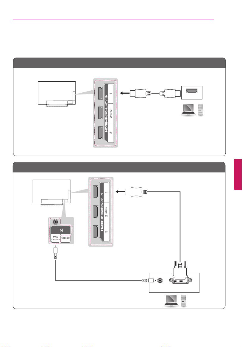
OPTICAL AUDIO IN
Digital Audio System
(*Not Provided)
Connecting to an Audio System
You may use an optional external audio system instead of the built-in speaker.
Digital Optical Audio Connection
Transmits a digital audio signal from the TV to an external device. Connect the external device and the TV
with the optical audio cable as shown in the following illustration.
Do not look into the optical output port. Looking at the laser beam may damage your vision.
Audio with ACP (Audio Copy Protection) function may block digital audio output.
NOTE
ENGENGLISH
31
MAKING CONNECTIONS
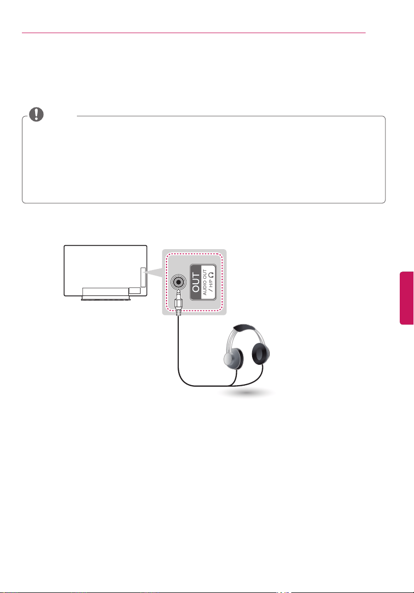
Connecting Headphones
(For EG9600, EF9500 series)
Listening to sound with headphones.
Do not use headsets (earphones) at high volume or for a long time. It may cause damage to your
hearing.
AUDIO menu options are disabled when headphones are connected.
When changing AV MODE with a headphone connected, the change is applied to video but not to audio.
Optical Digital Audio Out is not available when connecting a headphone.
Headphone impedance: 16 Ω
Max audio output: 0.627 mW to 1.334 mW
Headphone jack size: 3.5 mm (0.13 inches)
NOTE
(*Not Provided)
Headphone
ENG
ENGLISH
32
MAKING CONNECTIONS
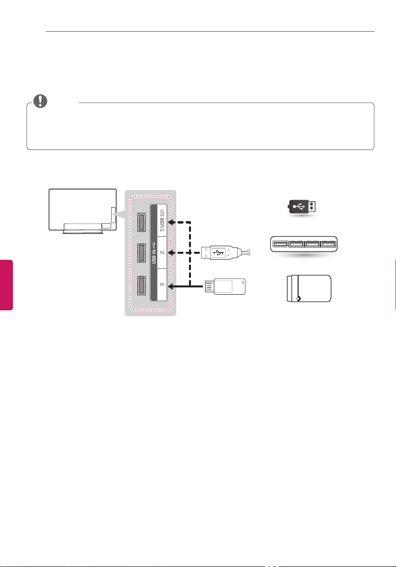
(*Not Provided)
Choose any USB input port to connect.
It does not matter which port you use.
USB / USB HUB / HDD
Connecting a USB Drive
Connect a USB storage device such as a USB flash thumbdrive, external hard drive, or a USB memory card
reader to the TV and access the SmartShare menu to use various multimedia files.
Some USB Hubs may not work. If a USB device connected using a USB Hub is not detected, connect it
directly to the USB port on the TV.
Some USB device may not work if it does not meet USB 3.0 standard. In case, connect it to USB IN 2 or
USB IN 3 port.
NOTE
ENGENGLISH
33
MAGIC REMOTE FUNCTIONS
MAGIC REMOTE FUNCTIONS
When the message
Magic remote control battery is low. Change the battery
. is
displayed, replace the battery. To install batteries, open the battery cover, replace
batteries (1.5 V AA) matching
and ends to the label inside the compartment, and
close the battery cover. Failure to match the correct polarities of the battery may cause
the battery to burst or leak, resulting in fire, personal injury, or ambient pollution. Be
sure to point the remote control at the remote control sensor on the TV. To remove
the batteries, perform the installation actions in reverse.
Do not mix old and new batteries, as this may damage the remote control.
CAUTION
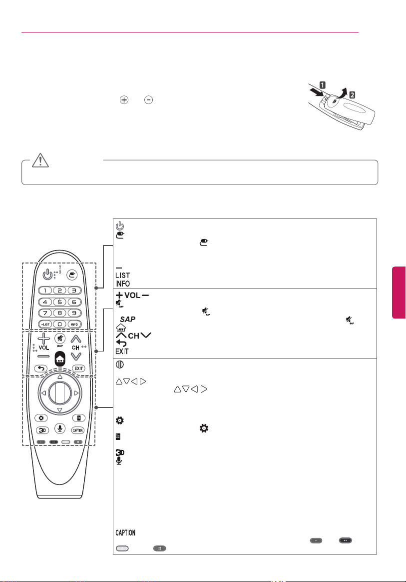
This remote uses infrared light. When in use, it should be pointed in the direction of the TV’s remote sensor.
(POWER) Turns the TV on or off.
(INPUT) Changes the input source.
* Pressing and holding the (INPUT) button displays all the lists of external
inputs.
Number buttons Enters numbers.
(DASH) Inserts a dash between numbers such as 2-1 and 2-2.
Accesses the saved channel list.
Views the information of the current channels and screen.
Adjusts the volume level.
(MUTE) Mutes all sounds.
* By pressing and holding the button, video descriptions function will be enabled.
* (Secondary Audio Program) Feature can also be enabled by pressing the key.
(Home) Accesses the Home menu.
Scrolls through the saved channels.
(BACK) Returns to the previous screen.
Clears all on-screen displays and returns to TV viewing.
Wheel (OK) Press the center of the Wheel button to select a menu. You can
change channels by using the Wheel button.
(up/down/left/right) Press the up, down, left or right button to scroll the
menu. If you press buttons while the pointer is in use, the pointer will
disappear from the screen and Magic Remote will operate like a general remote
control. To display the pointer on the screen again, shake Magic Remote to the left
and right.
(Q. Settings) Accesses the Quick Settings.
* Pressing and holding the (Q. Settings) button displays the Advanced menu.
(Screen remote) Displays the Screen Remote.
* Accesses the Universal Control Menu in some regions.
Used for viewing 3D video.
(Voice recognition)
Network connection is required to use the voice recognition function.
1. Press the voice recognition button.
2. Speak when the voice display window appears on the TV screen.
* Use the Magic Remote no further than 10 cm (4 inches) from your face.
* The voice recognition may fail when you speak too fast or too slowly.
* The recognition rate may vary depending upon the user’s characteristics (voice,
pronunciation, intonation, and speed) and the environment (noise and TV
volume).
Activates or deactivates the subtitles.
Color buttons These access special functions in some menus. (
Red, Green,
Yellow, Blue)
ENG
ENGLISH
34
MAGIC REMOTE FUNCTIONS / USING THE USER GUIDE
Registering Magic Remote
How to register the Magic Remote
(Wheel)
To use the Magic Remote, first pair it
with your TV.
1 Put batteries into the Magic Remote
and turn the TV on.
2 Point the Magic Remote at your TV
and press the
Wheel (OK)
on the
remote control.
* If the TV fails to register the Magic
Remote, try again after turning the TV
off and back on.
How to deregister the Magic Remote
(BACK)
(Home)
Press the (BACK) and (Home)
at the same time, for five seconds, to
unpair the Magic Remote with your TV.
»
Pressing and holding the
button
will let you cancel and re-register
Magic Remote at once.
How to Use Magic Remote
Shake the Magic Remote slightly to
the right and left or press
(Home),
(INPUT),
buttons to make
the pointer appear on the screen.
(In some TV models, the pointer will
appear when you turn the Wheel
button.)
If the pointer has not been used for
a certain period of time or Magic
Remote is placed on a flat surface,
then the pointer will disappear.
If the pointer does not move as you
wish, shake Magic Remote to the left
and right. The pointer will move to
the center of the screen.
The Magic Remote depletes batteries
faster than a normal remote due to
the additional features.
Precautions to Take
Use the remote control within the specified
range (within 10 m or 32.8 ft.) You may
experience communication failures when using
the device outside the coverage area or if there
are obstacles within the coverage area.
You may experience communication failures
depending on the accessories. Devices such as
a microwave oven and wireless LAN operate in
the same frequency band (2.4 GHz) as the Magic
Remote. This may cause communication failures.
The Magic Remote may not work properly if a
wireless router (AP) is within 1 meter (3.28 ft) of
the TV. Your wireless router should be more than
1 m (3.28 ft.) away from the TV.
Do not disassemble or heat the battery.
Do not drop the battery. Avoid extreme shocks
to the battery.
Inserting the battery in the wrong way may
result in explosion.
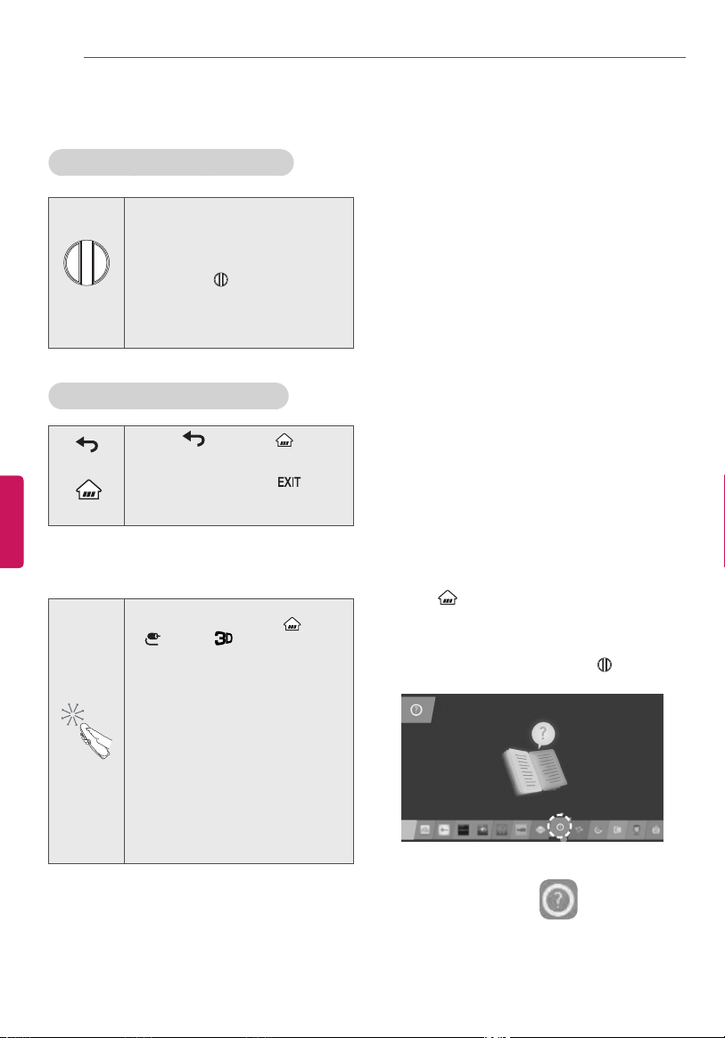
USING THE USER GUIDE
User Guide allows you to easily access detailed TV
information.
1
Press (Home) button to access the Home
menu.
2
Select User Guide and press the
Wheel (OK)
button.
ENGENGLISH
35
SPECIFICATIONS
SPECIFICATIONS
Product specifications may be changed without prior notice due to upgrade of product functions.
Power requirement AC 120 V ~ 50 / 60 Hz
Television System NTSC-M, ATSC, 64 & 256 QAM
Program Coverage
VHF 2-13, UHF 14-69, CATV 1-135, DTV 2-69, CADTV 1-135
External Antenna Impedance
75
Ω
Environment
condition
Operating
Temperature
0 °C to 40 °C (32 °F to 104 °F)
Operating
Humidity
Less than 80 %
Storage
Temperature
-20 °C to 60 °C (-4 °F to 140 °F)
Storage
Humidity
Less than 85 %
Thickness
Depth
MODELS
55EG9600
(55EG9600-UA)
65EG9600
(65EG9600-UA)
Dimensions
W x H x T (D)
With stand
1,226 x 760 x 213 (mm) 1,447 x 884 x 237 (mm)
48.2 x 29.9 x 8.3 (inches) 56.9 x 34.8 x 9.3 (inches)
Without stand
1,226 x 719 x 50.1 (87.8) (mm) 1,447 x 842 x 50.1 (102.5) (mm)
48.2 x 28.3 x 1.9 (3.4) (inches) 56.9 x 33.1 x 1.9 (4.0) (inches)
Weight
With stand 19 kg (41.8 Ibs) 26.9 kg (59.3 Ibs)
Without stand 15.3 kg (33.7 Ibs) 21.7 kg (47.8 Ibs)
Current value / Power consumption 3.9 A / 390 W 5.0 A / 500 W
MODELS
55EG9600
(55EG9600-UB)
65EG9600
(65EG9600-UB)
Dimensions
W x H x T (D)
With stand
1,226 x 760 x 213 (mm) 1,447 x 884 x 237 (mm)
48.2 x 29.9 x 8.3 (inches) 56.9 x 34.8 x 9.3 (inches)
Without stand
1,226 x 719 x 50.1 (87.8) (mm) 1,447 x 842 x 50.1 (102.5) (mm)
48.2 x 28.3 x 1.9 (3.4) (inches) 56.9 x 33.1 x 1.9 (4.0) (inches)
Weight
With stand 19 kg (41.8 Ibs) 26.9 kg (59.3 Ibs)
Without stand 15.3 kg (33.7 Ibs) 21.7 kg (47.8 Ibs)
Current value / Power consumption 3.6 A / 360 W 4.8 A / 480 W
MODELS
55EG9200
(55EG9200-UA)
Dimensions
W x H x T (D)
With stand
1,225 x 762 x 191 (mm)
48.2 x 30.0 x 7.5 (inches)
Without stand
1,225 x 719 x 48.9 (87.3) (mm)
48.2 x 28.3 x 1.9 (3.4) (inches)
Weight
With stand 16.5 kg (36.3 Ibs)
Without stand 13.2 kg (29.1 Ibs)
Current value / Power consumption 3.6 A / 360 W
ENG
ENGLISH
36
SPECIFICATIONS
MODELS
55EF9500
(55EF9500-UA)
65EF9500
(65EF9500-UA)
Dimensions
(W x H x D)
With stand
1,228 x 760 x 215 (mm) 1,450 x 883 x 236 (mm)
48.3 x 29.9 x 8.4 (inches) 57 x 34.7 x 9.2 (inches)
Without stand
1,228 x 718 x 50.1 (mm) 1,450 x 842 x 50.1 (mm)
48.3 x 28.2 x 1.9 (inches) 57 x 33.1 x 1.9 (inches)
Weight
With stand 17.2 kg (37.9 Ibs) 25.8 kg (56.8 Ibs)
Without stand 13.6 kg (29.9 Ibs) 21.2 kg (46.7 Ibs)
Current value / Power consumption 3.6 A / 360 W 4.8 A / 480 W
Wireless module (LGSBW41) Specifications
Wireless Lan Bluetooth
Standard IEEE 802.11a/b/g/n Standard Bluetooth Version 4.0
Frequency Range
2400 to 2483.5 MHz
5150 to 5250 MHz
5725 to 5850 MHz
Frequency Range 2400 to 2483.5 MHz
Output Powe
r
(Max.)
802.11a: 11.5 dBm
802.11b: 11 dBm
802.11g: 10.5 dBm
802.11n - 2.4 GHz: 11 dBm
802.11n - 5 GHz: 12.5 dBm
Output Power
(Max.)
10 dBm or Lower
Contains FCC ID: BEJLGSBW41 / Contains IC: 2703H-LGSBW41
Because band channel used by the country could be different, the user can not change or adjust the
operating frequency and this product is set for the regional frequency table.
This device should be installed and operated with minimum distance 20 cm (7.8 inches) between
the device and your body. And this phrase is for the general statement for consideration of user
environment.
ENGENGLISH
37
MAINTENANCE / TROUBLESHOOTING
MAINTENANCE
Cleaning Your TV
Clean your TV regularly to keep it at peak performance and to extend the product lifespan.
Make sure to turn the power off and disconnect the power cord and all other cables first.
When the TV is left unattended or unused for a long time, disconnect the power cord from the wall
outlet to prevent possible damage from lightning or power surges.
CAUTION
Screen, Frame, Cabinet, and Stand
To remove dust or light dirt, wipe the surface with a dry, clean, and soft cloth.
To remove major dirt, wipe the surface with a soft cloth dampened in clean water or a diluted mild
detergent. Then wipe immediately with a dry cloth.
Do not push, rub, or hit the surface with your fingernail or a sharp object, as this may result in
scratches on the screen and image distortions.
Do not use any chemicals, such as waxes, benzene, alcohol, thinners, insecticides, air fresheners, or
lubricants, as these may damage the screen’s finish and cause discoloration.
Do not spray liquid onto the surface. If water enters the TV, it may result in fire, electric shock, or
malfunction.
CAUTION
Power Cord
Remove the accumulated dust or dirt on the power cord regularly.
TROUBLESHOOTING
Problem Solution
Cannot control the TV with
the remote control.
Check the remote control sensor on the product and try again.
Check if there is any obstacle between the product and the remote control.
Check if the batteries are still working and properly installed (
to , to ).
No image display and no
sound is produced.
Check if the product is turned on.
Check if the power cord is connected to a wall outlet.
Check if there is a problem in the wall outlet by connecting other products.
The TV turns off suddenly.
Check the power control settings. The power supply may be interrupted.
Check if the
Sleep Timer/Timer Power Off
is activated in the
TIMERS
settings.
If there is no signal while the TV is on, the TV will turn off automatically after 15
minutes of inactivity.

THE CONSUMER ELECTRONICS INDUSTRY CARES
• Manufacturers, retailers and the rest of the consumer electronics industry are committed to
making home entertainment safe and enjoyable.
•
As you enjoy your television, please note that all televisions – new and old- must be supported on
proper stands or installed according to the manufacturer’s recommendations. Televisions that
are inappropriately situated on dressers, bookcases, shelves, desks, speakers, chests, carts, etc.,
may fall over, resulting in injury.
TUNE IN TO SAFETY
• ALWAYS follow the manufacturer’s recommendations for the safe installation of your television.
• ALWAYS read and follow all instructions for proper use of your television.
• NEVER
allow children to climb on or play on the television or the furniture on which the television
is placed.
• NEVER place the television on furniture that can easily be used as steps, such as a chest of
drawers.
• ALWAYS install the television where it cannot be pushed, pulled over or knocked down.
• ALWAYS route cords and cables connected to the television so that they cannot be tripped
over, pulled or grabbed.
WALL OR CEILING MOUNT YOUR TELEVISION
• ALWAYS contact your retailer about professional installation if you have any doubts about your
ability to safely mount your television.
• ALWAYS use a mount that has been recommended by the television manufacturer and has a
safety certication by an independent laboratory (such as UL, CSA, ETL).
• ALWAYS follow all instructions supplied by the television and mount manufacturers.
• ALWAYS make sure that the wall or ceiling where you are mounting the television is appropriate.
Some mounts are not designed to be mounted to walls and ceilings with steel studs or cinder
block construction. If you are unsure, contact a professional installer.
• Televisions can be heavy. A minimum of two people is required for a wall or ceiling mount
installation.
MOVING AN OLDER TELEVISION TO A NEW PLACE IN
YOUR HOME
• Many new television buyers move their older CRT televisions into a secondary room after the
purchase of a at-panel television. Special care should be made in the placement of older CRT
televisions.
• ALWAYS place your older CRT television on furniture that is sturdy and appropriate for its size
and weight.
• NEVER place your older CRT television on a dresser where children may be tempted to use the
drawers to climb.
• ALWAYS make sure your older CRT television does not hang over the edge of your furniture.
CHILD SAFETY:
PROPER TELEVISION PLACEMENT MATTERS
CE.org/safety
LG Customer Information Center
For inquires or comments, visit www.lg.com or call;
1-800-243-0000 USA, Consumer User
1-888-865-3026 USA, Commercial User
1-888-542-2623 CANADA
Register your product online!
www.lg.com
Declaration of Conformity
Trade Name LG
Model 55EG9600-UA, 65EG9600-UA
55EG9600-UB, 65EG9600-UB
55EF9500-UA, 65EF9500-UA
55EG9200-UA
Responsible
Party
LG Electronics Inc.
Address 1000 Sylvan Ave.
Englewood Cliffs NJ 07632
U.S.A
TEL 201 - 266 - 2534
The model and serial numbers of the TV are located on the
back and one side of the TV.
Record them below should you ever need service.
MODEL
SERIAL
This product qualifies for ENERGY
STAR® in the factory default (Home
configuration) setting.
Changing the factory default settings
or enabling other features may increase
power consumption that could exceed
the limits necessary to quality for
ENERGY STAR®.
Refer to ENERGY STAR.gov for more
information on the ENERGY STAR®
program.
(For 55EF9500, 65EF9500, 55EG9200)

OWNER’S MANUAL
EXTERNAL CONTROL
DEVICE SETUP
Please read this manual carefully before operating the set and retain it for
future reference.
www.lg.com
2
ENG
ENGLISH
2
KEY CODES
KEY CODES
• This feature is not available for all models.
Code
(Hexa)
Function Note
Code
(Hexa)
Function Note
00 CH +, PR + R/C Button 53 List R/C Button
01 CH -, PR - R/C Button 5B Exit R/C Button
02 Volume + R/C Button 60 PIP(AD) R/C Button
03 Volume - R/C Button 61 Blue R/C Button
06 > (Arrow Key / Right Key) R/C Button 63 Yellow R/C Button
07 < (Arrow Key / Left Key) R/C Button 71 Green R/C Button
08 Power R/C Button 72 Red R/C Button
09 Mute R/C Button 79 Ratio / Aspect Ratio R/C Button
0B Input R/C Button 91 AD (Audio Description) R/C Button
0E SLEEP R/C Button 7A User Guide R/C Button
0F TV, TV/RAD R/C Button 7C Smart / Home R/C Button
10 - 19 * Number Key 0 - 9 R/C Button 7E SIMPLINK R/C Button
1A Q.View / Flashback R/C Button 8E ►► (Forward) R/C Button
1E FAV (Favorite Channel) R/C Button 8F ◄◄ (Rewind) R/C Button
20 Text (Teletext) R/C Button AA Info R/C Button
21 T. Opt (Teletext Option) R/C Button AB Program Guide R/C Button
28 Return (BACK) R/C Button B0 ► (Play) R/C Button
30 AV (Audio / Video) Mode R/C Button B1
ꕗ (Stop / File List)
R/C Button
39 Caption/Subtitle R/C Button BA
ꕘ (Freeze / Slow Play /
Pause)
R/C Button
40 Λ
(Arrow Key / Cursor Up)
R/C Button BB Soccer R/C Button
41
V (Arrow Key / Cursor
Down)
R/C Button BD
ꔄ (REC)
R/C Button
42 My Apps R/C Button DC 3D R/C Button
43 Menu / Settings R/C Button 99 AutoConfig R/C Button
44 OK / Enter R/C Button 9F App / * R/C Button
45 Q.Menu R/C Button
4C List, - (ATSC Only) R/C Button
* Key code 4C (0x4C) is available on ATSC/ISDB models which use major/minor channel.
(For South Korea, Japan, North America, Latin America except Colombia models)
3
ENGENGLISH
3
EXTERNAL CONTROL DEVICE SETUP
EXTERNAL CONTROL DEVICE SETUP
• Image shown may differ from your TV.
Connect the USB to Serial converter/RS-232C input jack to an external control device (such as a computer
or an A/V control system) to control the product’s functions externally.
Note: The type of control port on the TV can be different between model series.
* Please be advised that not all models support this type of connectivity.
* Cable is not provided.
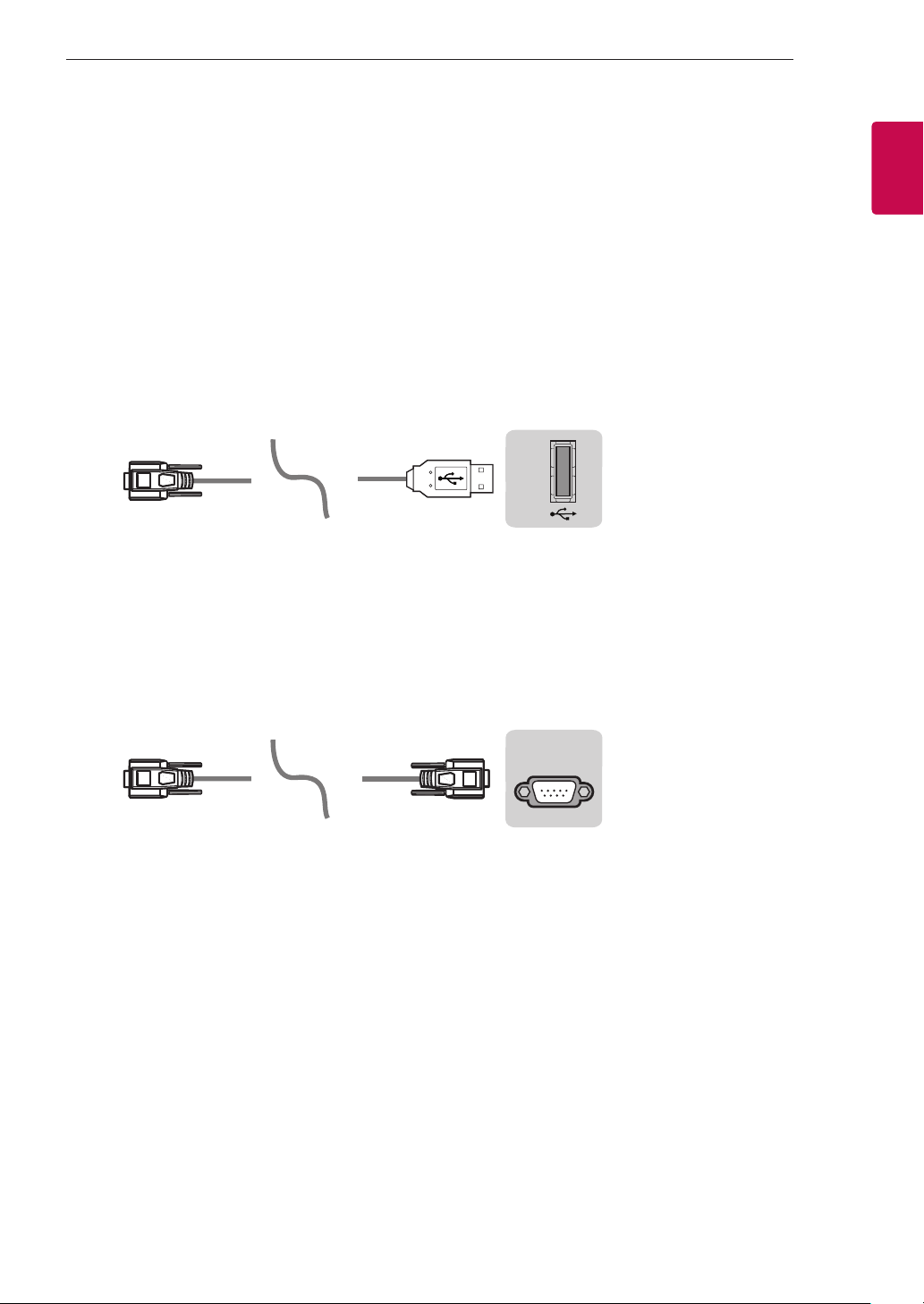
USB to Serial converter with USB Cable
USB Type
USB IN
(TV)
(PC )
(PC )
RS-232C IN
(CONTROL & SERVICE)
(TV)
(TV)
(PC )
(TV)
(PC )
SERVICE ONLY
RS-232C IN
(CONTROL & SERVICE)
RS-232C IN
(CONTROL & SERVICE)
1
3
2
1
3
2
• LGTV supports PL2303 chip-based (Vendor ID : 0x0557, Product ID : 0x2008) USB to serial converter
which is not made nor provided by LG.
• It can be purchased from computer stores that carry accessories for IT support professionals.
RS-232C With RS232C Cable
DE9 (D-Sub 9pin) Type
• You need to purchase the RS-232C (DE9, D-Sub 9pin female-to-female type) to RS-232C cable required
for the connection between the PC and the TV, which is specified in the manual.
USB IN
(TV)
(PC )
(PC )
RS-232C IN
(CONTROL & SERVICE)
(TV)
(TV)
(PC )
(TV)
(PC )
SERVICE ONLY
RS-232C IN
(CONTROL & SERVICE)
RS-232C IN
(CONTROL & SERVICE)
1
3
2
1
3
2
The connection interface may differ from your TV.
4
ENG
ENGLISH
4
EXTERNAL CONTROL DEVICE SETUP
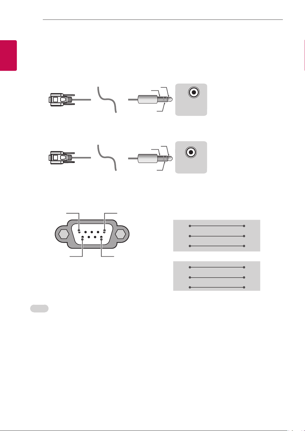
Phone jack Type
• You need to purchase the phone-jack to RS-232 cable required for the connection between the PC and
the TV, which is specified in the manual.
* For other models, connect to the USB port.
* The connection interface may differ from your TV.
USB IN
(TV)
(PC )
(PC )
RS-232C IN
(CONTROL & SERVICE)
(TV)
(TV)
(PC
)
(TV)
(PC )
SERVICE ONLY
RS-232C IN
(CONTROL & SERVICE)
RS-232C IN
(CONTROL & SERVICE)
1
3
2
1
3
2
- or
USB IN
(TV)
(PC )
(PC )
RS-232C IN
(CONTROL & SERVICE)
(TV)
(TV)
(PC )
(TV)
(PC
)
SERVICE ONLY
RS-232C IN
(CONTROL & SERVICE)
RS-232C IN
(CONTROL & SERVICE)
1
3
2
1
3
2
Customer Computer RS-232C configurations
3-Wire Configurations(Not standard)
1
6
5
9
PC TV
RXD 2 2 TXD
TXD 3 1 RXD
GND 5 3 GND
OR
RXD 3 2 TXD
TXD 2 1 RXD
GND 5 3 GND
D-Sub 9 Phone
RS-232C
(Serial port)
Set ID
For Set ID number, see "Real Data Mapping" on p.6
1. Press SETTINGS to access the main menus.
2. Press the Navigation buttons to scroll to (*General → About this TV or OPTION) and press OK.
3. Press the Navigation buttons to scroll to SET ID and press OK.
4. Scroll left or right to select a set ID number and select CLOSE. The adjustment range is 1-99.
5. When you are finished, press EXIT.
* (Depending on model)
5
ENGENGLISH
5
EXTERNAL CONTROL DEVICE SETUP
Communication Parameters
• Baud rate : 9600 bps (UART)
• Data length : 8 bits
• Parity : None
• Stop bit : 1 bit
• Communication code : ASCII code
• Use a crossed (reverse) cable.
Command reference list
(Depending on model)
COMMAND1 COMMAND2
DATA
(Hexadecimal)
COMMAND1 COMMAND2
DATA
(Hexadecimal)
01. Power* k a 00 to 01 15. Balance k t 00 to 64
02. Aspect
Ratio
k c (p.7)
16. Color
(Colour)
Temperature
x u 00 to 64
03. Screen
Mute
k d (p.7)
17. ISM
Method (Only
Plasma TV)
j p (p.8)
04. Volume
Mute
k e 00 to 01 18. Equalizer j v (p.8)
05. Volume
Control
k f 00 to 64
19. Energy
Saving
j q 00 to 05
06. Contrast k g 00 to 64
20. Tune
Command
m a (p.9)
07.
Brightness
k h 00 to 64
21. Channel
(Programme)
Add/Del(Skip)
m b 00 to 01
08. Color/
Colour
k i 00 to 64 22. Key m c Key Codes
09. Tint k j 00 to 64
23. Control
Backlight,
Control Panel
Light
m g 00 to 64
10.
Sharpness
k k 00 to 32
24. Input
select (Main)
x b (p.11)
11. OSD
Select
k l 00 to 01
25. 3D (Only
3D models)
x t (p.11)
12. Remote
Control Lock
Mode
k m 00 to 01
26. Extended
3D (Only 3D
models)
x v (p.11)
13. Treble k r 00 to 64
27. Auto
Configure
j u (p.12)
14. Bass k s 00 to 64
* Note: During playing or recording media, all commands except Power (ka) and Key (mc) are not
executed and treated as NG.
With RS232C cable, TV can communicate "ka command" in power-on or power-off status. but with
USB-to-Serial converter cable, the command works only if TV is on.

6
ENG
ENGLISH
6
EXTERNAL CONTROL DEVICE SETUP
Transmission / Receiving Protocol
Transmission
[Command1][Command2][ ][Set ID][ ][Data][Cr]
[Command 1] : First command to control the TV. (j, k, m or x)
[Command 2] : Second command to control the TV.
[Set ID] : You can adjust the [Set ID] to choose desired monitor ID number in option menu.
Adjustment range in TV is 1 to 99. If [Set ID] value is selected to ‘0’, every connected set
can be controlled.
* [Set ID] is indicated as decimal (1 to 99) on menu and as Hexadecimal (0x00 to 0x63) on
transmission/receiving protocol.
[DATA] : To transmit command data (hexadecimal). Transmit ‘FF’ data to read status of command.
[Cr] : Carriage Return - ASCII code ‘0x0D’
[ ] : Space – ASCII code ‘0x20’
OK Acknowledgement
[Command2][ ][Set ID][ ][OK][Data][x]
* The set transmits ACK (acknowledgement) based on this format when receiving normal data. At this time,
if the data is data read mode, it indicates present status data. If the data is data write mode, it returns the
data of the PC computer.
Error Acknowledgement
[Command2][ ][Set ID][ ][NG][Data][x]
* The set transmits ACK (acknowledgement) based on this format when receiving abnormal data from
non-viable functions or communication errors.
Data 00: Illegal Code
Real data mapping (Hexadecimal b Decimal)
* When you enter the [data] in hexadecimal, refer to following conversion table.
* Channel Tune (ma) Command uses two-byte hexadecimal value([data]) to select channel number.
00 : Step 0 32 : Step 50 (Set ID 50) FE : Step 254
01 : Step 1 (Set ID 1) 33 : Step 51 (Set ID 51) FF : Step 255
... ... ...
0A : Step 10 (Set ID 10) 63 : Step 99 (Set ID 99) 01 00 : Step 256
... ... ...
0F : Step 15 (Set ID 15) C7 : Step 199 27 0E : Step 9998
10 : Step 16 (Set ID 16) C8 : Step 200 27 0F : Step 9999
... ... ...

7
ENGENGLISH
7
EXTERNAL CONTROL DEVICE SETUP
* Commands may work differently depending on model and signal.
01. Power (Command: k a)
► To control Power *On or Off of the set.
Transmission[k][a][ ][Set ID][ ][Data][Cr]
Data 00 : Power Off 01 : *Power On
Ack [a][ ][Set ID][ ][OK/NG][Data][x]
► To Show TV is Power On or *Off
Transmission [k][a][ ][Set ID][ ][FF][Cr]
Ack [a][ ][Set ID][ ][OK][Data][x]
* Similarly, if other functions transmit ‘FF’ data
based on this format, Acknowledgement feedback
presents status about each function.
02. Aspect Ratio (Command: k c)
(Main Picture Size)
► To adjust the screen format. (Main picture format)
You can also adjust the screen format using the
Aspect Ratio in the Q.MENU. or PICTURE menu.
Transmission [k][c][ ][Set ID][ ][Data][Cr]
Data 01 : Normal screen
(4:3)
02 : Wide screen
(16:9)
04 : Zoom
05 : Zoom 2
(Latin America
except Colombia
Only)
06 : Set by Program/
Original
07 : 14:9
(Europe, Colombia, Mid-East,
Asia except South Korea and
Japan)
09 : * Just Scan
0B : Full Wide
(Europe, Colombia, Mid-
East, Asia except South
Korea and Japan)
10 to 1F : Cinema Zoom 1 to 16
0c : 21:9 (Depending on model)
Ack [c][ ][Set ID][ ][OK/NG][Data][x]
* Using the PC input, you select either 16:9 or 4:3
screen aspect ratio.
* In DTV/HDMI/Component mode (high-definition),
Just Scan is available.
* Full wide mode may work differently based on
model and is supported for DTV fully, and ATV,
AV partially.
03. Screen Mute (Command: k d)
► To select screen mute on/off.
Transmission [k][d][ ][Set ID][ ][Data][Cr]
Data 00 : Screen mute off (Picture on)
Video mute off
01 : Screen mute on (Picture off)
10 : Video mute on
Ack [d][ ][Set ID][ ][OK/NG][Data][x]
* In case of video mute on only, TV will display On
Screen Display(OSD). But, in case of Screen mute
on, TV will not display OSD.
04. Volume Mute (Command: k e)
► To control volume mute on/off.
You can also adjust mute using the MUTE button
on remote control.
Transmission [k][e][ ][Set ID][ ][Data][Cr]
Data 00 : Volume mute on (Volume off)
01 : Volume mute off (Volume on)
Ack [e][ ][Set ID][ ][OK/NG][Data][x]
05. Volume Control (Command: k f)
► To adjust volume.
You can also adjust volume with the volume
buttons on remote control.
Transmission [k][f][ ][Set ID][ ][Data][Cr]
Data Min : 00 to Max : 64
Ack [f][ ][Set ID][ ][OK/NG][Data][x]
06. Contrast (Command: k g)
► To adjust screen contrast.
You can also adjust contrast in the PICTURE
menu.
Transmission [k][g][ ][Set ID][ ][Data][Cr]
Data Min : 00 to Max : 64
Ack [g][ ][Set ID][ ][OK/NG][Data][x]
07. Brightness (Command: k h)
► To adjust screen brightness.
You can also adjust brightness in the PICTURE
menu.
Transmission [k][h][ ][Set ID][ ][Data][Cr]
Data Min : 00 to Max : 64
Ack [h][ ][Set ID][ ][OK/NG][Data][x]
08. Color/Colour (Command: k i)
► To adjust the screen Color(Colour).
You can also adjust colour in the PICTURE menu.
Transmission [k][i][ ][Set ID][ ][Data][Cr]

8
ENG
ENGLISH
8
EXTERNAL CONTROL DEVICE SETUP
Data Min : 00 to Max : 64
Ack [i][ ][Set ID][ ][OK/NG][Data][x]
09. Tint (Command: k j)
► To adjust the screen tint.
You can also adjust tint in the PICTURE menu.
Transmission [k][j][ ][Set ID][ ][Data][Cr]
Data Red : 00 to Green : 64
Ack [j][ ][Set ID][ ][OK/NG][Data][x]
10. Sharpness (Command: k k)
► To adjust the screen sharpness.
You can also adjust sharpness in the PICTURE
menu.
Transmission [k][k][ ][Set ID][ ][Data][Cr]
Data Min : 00 to Max : 32
Ack [k][ ][Set ID][ ][OK/NG][Data][x]
11. OSD Select (Command: k l)
► To select OSD (On Screen Display) on/off when
controlling remotely.
Transmission [k][l][ ][Set ID][ ][Data][Cr]
Data 00 : OSD off 01 : OSD on
Ack [l][ ][Set ID][ ][OK/NG][Data][x]
12. Remote control lock mode (Command: k m)
► To lock the front panel controls on the monitor and
remote control.
Transmission [k][m][ ][Set ID][ ][Data][Cr]
Data 00 : Lock off 01 : Lock on
Ack [m][ ][Set ID][ ][OK/NG][Data][x]
* If you are not using the remote control, use this
mode.
When main power is off & on (plug-off and plug-in,
after 20 - 30 seconds), external control lock is
released.
* In the standby mode (DC off by off timer or ‘ka’,
‘mc’ command), and if key lock is on, TV will not
turn on by power on key of IR & Local Key.
13. Treble (Command: k r)
► To adjust treble.
You can also adjust in the AUDIO menu.
Transmission [k][r][ ][Set ID][ ][Data][Cr]
Data Min : 00 to Max : 64
Ack [r][ ][Set ID][ ][OK/NG][Data][x]
* (Depending on model)
14. Bass (Command: k s)
► To adjust Bass.
You can also adjust in the AUDIO menu.
Transmission [k][s][ ][Set ID][ ][Data][Cr]
Data Min : 00 to Max : 64
Ack [s][ ][Set ID][ ][OK/NG][Data][x]
* (Depending on model)
15. Balance (Command: k t)
► To adjust balance.
You can also adjust balance in the AUDIO menu.
Transmission [k][t][ ][Set ID][ ][Data][Cr]
Data Min : 00 to Max : 64
Ack [t][ ][Set ID][ ][OK/NG][Data][x]
16. Color(Colour) Temperature (Command: x u)
► To adjust colour temperature. You can also adjust
Color(Colour) Temperature in the PICTURE menu.
Transmission [x][u][ ][Set ID][ ][Data][Cr]
Data Min : 00 to Max : 64
Ack [u][ ][Set ID][ ][OK/NG][Data][x]
17. ISM Method (Command: j p) (Only Plasma TV)
► To control the ISM method. You can also adjust
ISM Method in OPTION menu.
Transmission [j][p][ ][Set ID][ ][Data][Cr]
Data Min : 02: Orbiter
08: Normal
20: Color(Colour) Wash
Ack [p][ ][Set ID][ ][OK/NG][Data][x]
18. Equalizer (Command : j v)
► Adjust EQ of the set.
Transmission [j][v][ ][Set ID][ ][Data][Cr]
0 0 0 0 0 0 0 0
MSB
Frequency Data
LSB
7 6 5
Frequency
4 3 2 1 0 Step
0 0 0
1st Band
0 0 0 0 0
0(decimal)
0 0 1
2nd Band
0 0 0 0 1
1(decimal)
0 1 0
3rd Band
... ... ... ... ...
...
0 1 1
4th Band
0 0 0 1 1
19(decimal)

9
ENGENGLISH
9
EXTERNAL CONTROL DEVICE SETUP
1 0 0
5th Band
0 0 1 0 1
20(decimal)
Acknowledgement [v][ ][Set ID][ ][OK/NG][Data][x]
* It depends on model, and can adjust when sound
mode is EQ adjustable value.
19. Energy Saving (Command: j q)
► To reduce the power consumption of the TV. You
can also adjust Energy Saving in PICTURE menu.
Transmission [j][q][ ][Set ID][ ][Data][Cr]
Data
00 : Off
01 : Minimum
02 : Medium
03 : Maximum
04 : Auto (For LCD TV / LED TV) /
Intelligent sensor (For PDP TV)
05 : Screen off
* (Depending on model)
Ack [q][ ][Set ID][ ][OK/NG][Data][x]
20. Tune Command (Command: m a)
* This command may work differently depending on
model and signal.
• For Europe, Mid-East, Colombia, Asia except
South Korea and Japan Model
► Select channel to following physical number.
Transmission [m][a][ ][Set ID][ ][Data 00][ ]
[Data 01][ ][Data 02][Cr]
* Analog Antenna/Cable
[Data 00][Data 01] Channel Data
Data 00 : High byte channel data
Data 01 : Low byte channel data
- 00 00 ~ 00 C7 (Decimal : 0 ~ 199)
Data 02 : Input Source (Analog)
- 00 : Antenna TV (ATV)
- 80 : Cable TV (CATV)
* Digital Antenna/Cable/Satellite
[Data 00][Data 01]: Channel Data
Data 00 : High Channel data
Data 01 : Low Channel data
- 00 00 ~ 27 0F (Decimal: 0 ~ 9999)
Data 02 : Input Source (Digital)
- 10 : Antenna TV (DTV)
- 20 : Antenna Radio (Radio)
- 40 : Satellite TV (SDTV)
- 50 : Satellite Radio (S-Radio)
- 90 : Cable TV (CADTV)
- a0 : Cable Radio (CA-Radio)
* Tune Command Examples:
1. Tune to the Analog antenna (PAL) Channel 10.
Set ID = All = 00
Data 00 & 01 = Channel Data is 10 = 00 0a
Data 02 = Analog Antenna TV = 00
Result = ma 00 00 0a 00
2. Tune to the digital antenna (DVB-T) Channel 01.
Set ID = All = 00
Data 00 & 01 = Channel Data is 1 = 00 01
Data 02 = Digital Antenna TV = 10
Result = ma 00 00 01 10
3. Tune to the satellite (DVB-S) Channel 1000.
Set ID = All = 00
Data 00 & 01 = Channel Data is 1000 = 03 E8
Data 02 = Digital Satellite TV = 40
Result = ma 00 03 E8 40
Ack [a][ ][Set ID][ ][OK][Data 00][Data 01]
[Data 02][x][a][ ][Set ID][ ][NG][Data 00][x]
• For South Korea, North/Latin America except
Colombia Model
► To tune channel to following physical/major/minor
number.
Transmission [m][a][ ][0][ ][Data00][ ][Data01]
[ ][Data02][ ][Data03][ ][Data04][ ][Data05][Cr]
Digital channels have a Physical, Major, and Minor
channel number. The Physical number is the actual
digital channel number, the Major is the number that
the channel should be mapped to, and the Minor is
the sub-channel. Since the ATSC tuner automatically
maps the channel from the Major / Minor number,
the Physical number is not required when sending a
command in Digital.
* Analog Antenna/Cable
Data 00 : Physical Channel Number
- Antenna (ATV) : 02~45 (Decimal: 2 ~ 69)
- Cable (CATV) : 01, 0E~7D (Decimal : 1, 14~125)
[Data 01 ~ 04]: Major/Minor Channel Number
Data 01 & 02: xx (Don't care)
Data 03 & 04: xx (Don't care)
Data 05: Input Source (Analog)
- 00 : Antenna TV (ATV)
- 01 : Cable TV (CATV)
* Digital Antenna/Cable
Data 00 : xx (Don't care)
[Data 01][Data 02]: Major Channel Number
Data 01 : High byte Channel Data
Data 02 : Low byte Channel Data
- 00 01 ~ 27 0F (Decimal: 1 ~ 9999)
[Data 03][Data 04]: Minor Channel Number
Data 03 : High byte Channel Data
Data 04 : Low byte Channel Data
Data 05 : Input Source (Digital)
- 02 : Antenna TV (DTV) – Use Physical Channel
Number
- 06 : Cable TV (CADTV) – Use Physical Channel

10
ENG
ENGLISH
10
EXTERNAL CONTROL DEVICE SETUP
Number
- 22 : Antenna TV (DTV) – Don’t Use Physical
Channel Number
- 26 : Cable TV (CADTV) - Don’t Use Physical
Channel Number
- 46 : Cable TV (CADTV) – Use Major Channel
Number Only (One Part Channel)
Two bytes are available for each major and minor
channel data, but usually the low byte is used alone
(high byte is 0).
* Tune Command Examples:
1. Tune to the Analog cable (NTSC) channel 35.
Set ID = All = 00
Data 00 = Channel Data is 35 = 23
Data 01 & 02 = No Major = 00 00
Data 03 & 04 = No Minor = 00 00
Data 05 = Analog Cable TV = 01
Total = ma 00 23 00 00 00 00 01
2. Tune to the digital antenna (ATSC) channel 30-3.
Set ID = All = 00
Data 00 = Don’t know Physical = 00
Data 01 & 02 = Major is 30 = 00 1E
Data 03 & 04 = Minor is 3 = 00 03
Data 05 = Digital Antenna TV = 22
Total = ma 00 00 00 1E 00 03 22
Ack [a][ ][Set ID][ ][OK][Data 00][Data 01]
[Data 02][Data 03][Data 04][Data 05]
[x][a][ ][Set ID][ ][NG][Data 00][x]
• For Japan Model
► To tune channel to following physical/major/minor
number.
Transmission [m][a][ ][0][ ][Data00][ ][Data01]
[ ][Data02][ ][Data03][ ][Data04][ ][Data05][Cr]
* Digital Antenna/Satellite
Data 00: xx (Don't care)
[Data 01][Data 02]: Major Channel Number
Data 01: High byte Channel Data
Data 02: Low byte Channel Data
- 00 01 ~ 27 0F (Decimal: 1 ~ 9999)
[Data 03][Data 04]: Minor/Branch Channel Number
(Don’t care in Satellite)
Data 03: High byte Channel Data
Data 04: Low byte Channel Data
Data 05 : Input Source (Digital/Satellite for Japan)
- 02 : Antenna TV (DTV)
- 07 : BS (Broadcasting Satellite)
- 08 : CS1 (Communication Satellite 1)
- 09 : CS2 (Communication Satellite 2)
* Tune Command Examples:
1
Tune to the digital antenna (ISDB-T) channel 17-1
.
Set ID = All = 00
Data 00 = Don’t know Physical = 00
Data 01 & 02 = Major is 17 = 00 11
Data 03 & 04 = Minor/Branch is 1 = 00 01
Data 05 = Digital Antenna TV = 02
Total = ma 00 00 00 11 00 01 02
2. Tune to the BS (ISDB-BS) channel 30.
Set ID = All = 00
Data 00 = Don’t know Physical = 00
Data 01 & 02 = Major is 30 = 00 1E
Data 03 & 04 = Don’t Care = 00 00
Data 05 = Digital BS TV = 07
Total = ma 00 00 00 1E 00 00 07
* This feature is varied based on the model.
Ack [a][ ][Set ID][ ][OK][Data 00][Data 01]
[Data 02][Data 03][Data 04][Data 05]
[x][a][ ][Set ID][ ][NG][Data 00][x]
21. Channel(Programme) Add/Del(Skip)
(Command: m b)
► To skip current channel(programme) for next time.
Transmission [m][b][ ][Set ID][ ][Data][Cr]
Data 00 : Del(ATSC,ISDB)/Skip(DVB) 01 : Add
Ack [b][ ][Set ID][ ][OK/NG][Data][x]
* Set the saved channel status to del(ATSC, ISDB)/
skip(DVB) or add.
22. Key (Command: m c)
► To send IR remote key code.
Transmission [m][c][ ][Set ID][ ][Data][Cr]
Data Key code - p.2.
Ack [c][ ][Set ID][ ][OK/NG][Data][x]
23. Control Backlight (Command: m g)
• For LCD TV / LED TV
► To control the backlight.
Transmission [m][g][ ][Set ID][ ][Data][Cr]
Data Min : 00 to Max : 64
Ack [g][ ][Set ID][ ][OK/NG][Data][x]
Control Panel Light (Command: m g)
• For Plasma TV
► To control the panel light.
Transmission [m][g][ ][Set ID][ ][Data][Cr]
Data Min : 00 to Max : 64
Ack [g][ ][Set ID][ ][OK/NG][Data][x]

11
ENGENGLISH
11
EXTERNAL CONTROL DEVICE SETUP
24. Input select (Command: x b)
(Main Picture Input)
► To select input source for main picture.
Transmission [x][b][ ][Set ID][ ][Data][Cr]
Data
00 : DTV
02 : Satellite DTV
ISDB-BS (Japan)
03 : ISDB-CS1 (Japan)
04 : ISDB-CS2 (Japan)
11 : CATV
01 : CADTV
10 : ATV
20 : AV or AV1 21 : AV2
40 : Component1
60 : RGB
41 : Component2
90 : HDMI1
92 : HDMI3
91 : HDMI2
93 : HDMI4
Ack [b][ ][Set ID][ ][OK/NG][Data][x]
* This function depends on model and signal.
25. 3D(Command: x t) (only 3D models)
(Depending on model)
► To change 3D mode for TV.
Transmission [x][t][ ][Set ID][ ][Data 00][ ][Data 01]
[ ][Data 02][ ][Data 03][Cr]
* (Depending on model)
Data Structure
[Data 00] 00 : 3D On
01 : 3D Off
02 : 3D to 2D
03 : 2D to 3D
[Data 01] 00 : Top and Bottom
01 : Side by Side
02 : Check Board
03 : Frame Sequential
04 : Column interleaving
05 : Row interleaving
[Data 02] 00 : Right to Left
01 : Left to Right
[Data 03] 3D Effect(3D Depth): Min : 00 - Max : 14
(*transmit by Hexadecimal code)
* [Data 02], [Data 03] functions depend on model
and signal.
* If [Data 00] is 00 (3D On), [Data 03] has no
meaning.
* If [Data 00] is 01 (3D off) or 02 (3D to 2D), [Data
01], [Data 02] and [Data 03] have no meaning.
* If [Data 00] is 03 (2D to 3D), [Data 01] and
[Data 02] have no meaning.
* If [Data 00] is 00 (3D On) or 03 (2D to 3D), [Data
03] works when 3D Mode (Genre) is manual only.
* All 3D pattern options ([Data 01]) may not be
available according to broadcasting/video signal.
[Data 00] [Data 01] [Data 02] [Data 03]
00 O O O
01 X X X
02 X X X
03 X O O
X : don’t care
Ack [t][ ][Set ID][ ][OK][Data00][Data01][Data02]
[Data03][x]
[t][ ][Set ID][ ][NG][Data00][x]
26. Extended 3D(Command: x v) (only 3D models)
(Depending on model)
► To change 3D option for TV.
Transmission [x][v][ ][Set ID][ ][Data 00][ ]
[Data 01][Cr]
[Data 00] 3D option
00 : 3D Picture Correction
01 : 3D Depth (3D Mode is Manual Only)
02 : 3D Viewpoint
06 : 3D Color Correction
07 : 3D Sound Zooming
08 : Normal Image View
09 : 3D Mode (Genre)
[Data 01] It has own range for each 3D option
determined by [Data 00].
1) When [Data 00] is 00
00 : Right to Left
01 : Left to Right
2) When [Data 00] is 01, 02
Data Min: 0 - Max: 14 (*transmit by Hexadecimal
code)
Data value range(0 - 20) converts Viewpoint range
(-10 - +10) automatically (Depending on model)
* This option works when 3D Mode (Genre) is manual
only.
3) When [Data 00] is 06, 07
00 : Off
01 : On
4) When [Data 00] is 08
00 : Revert to 3D video from 3D-to-2D
converted 2D video
01 : Change 3D video to 2D video, except
2D-to-3D video
* If conversion condition doesn’t meet, command is
treated as NG.
5) When [Data 00] is 09
00 : Standard
02 : Cinema
04 : Manual
01 : Sport
03 : Extreme
05 : Auto
Ack [v][ ][Set ID][ ][OK][Data00][Data01][x]
[v][ ][Set ID][ ][NG][Data00][x]

12
ENG
ENGLISH
12
EXTERNAL CONTROL DEVICE SETUP
27. Auto Configure (Command: j u)
(Depending on model)
► To adjust picture position and minimize image
shaking automatically. It works only in RGB (PC)
mode.
Transmission [j][u][ ][Set ID][ ][Data][Cr]
Data 01 : To set
Ack [u][ ][Set ID][ ][OK/NG][Data][x]