Loading ...
Loading ...
Loading ...
2008/June/16 CD-DK890N_US
8
CD-DK890N
General Information
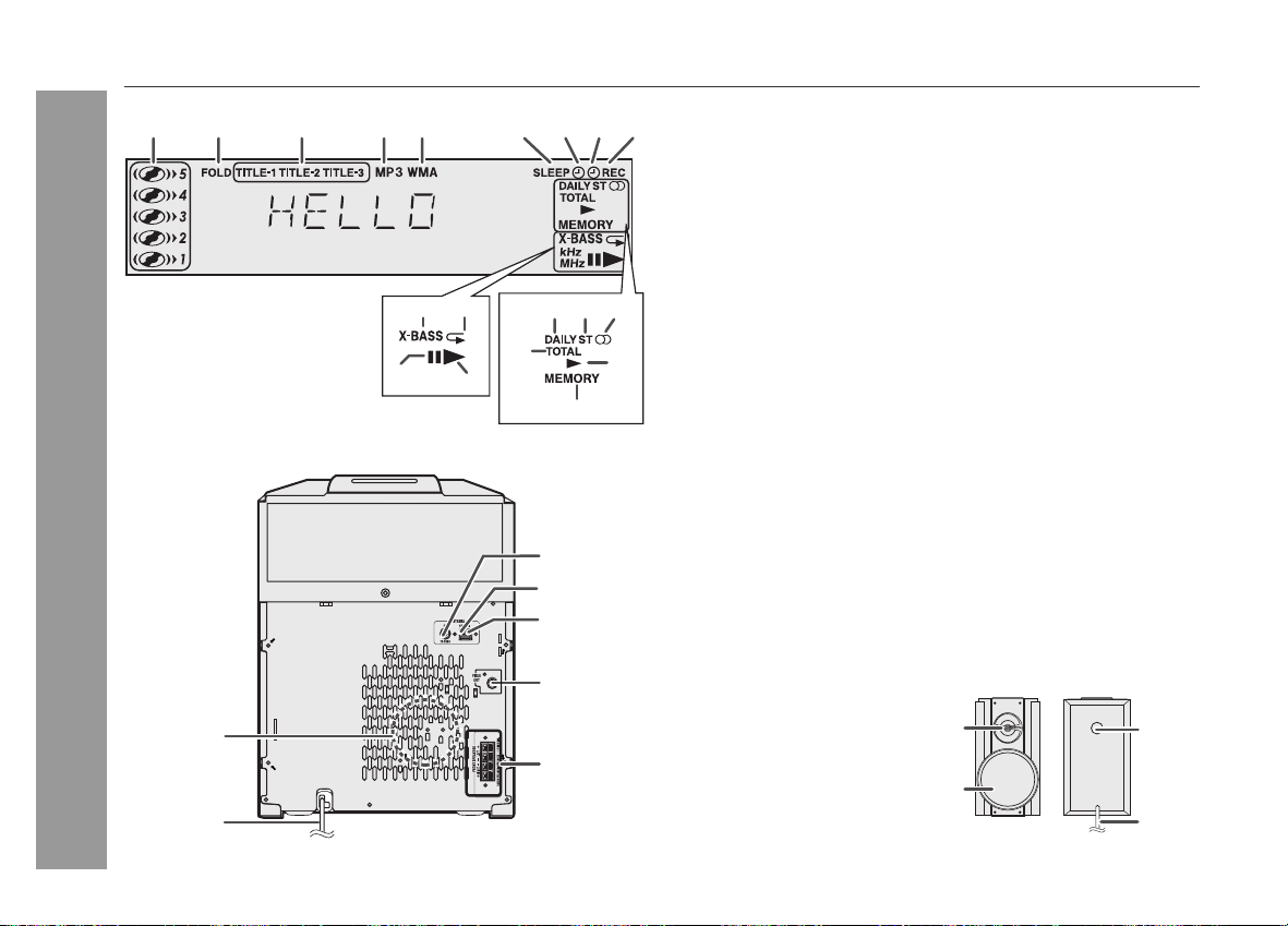
Controls and indicators (continued)
Display
Reference page
1. Disc Number Indicators ........................................................23
2. MP3/WMA Folder Indicator .................................................. 26
3. MP3/WMA Title Indicators .................................................... 26
4. MP3 Indicator ........................................................................ 21
5. WMA Indicator .......................................................................21
6. Sleep Indicator ...................................................................... 38
7. Timer Play Indicator .............................................................. 37
8. Timer Recording Indicator ................................................... 37
9. Tape 2 Record Indicator ................................................ 34, 35
10. MP3/WMA Total Indicator .................................................... 27
11. Daily Timer Indicator ............................................................ 37
12. FM Stereo Mode Indicator ................................................... 30
13. FM Stereo Receiving Indicator ............................................ 30
14.Tape Play Indicator ................................................................ 32
15. Memory Indicator ........................................................... 25, 31
16. Extra Bass Indicator ............................................................. 14
17. Disc Repeat Play Indicator .................................................. 24
18. Disc Pause Indicator ............................................................ 22
19. Disc Play Indicator ............................................................... 21
Rear panel
Reference page
1. Cooling Fan ........................................................................... 12
2. AC Power Cord ..................................................................... 12
3. FM 75 Ohms Antenna Jack .................................................. 11
4. AM Antenna Ground Terminal ............................................ 11
5. AM Loop Antenna Terminal ................................................. 11
6. Video Out Jack ..................................................................... 39
7. Front Speaker Terminals ..................................................... 11
Speaker system
A
C INPUT
C I NPUT
3
7
4
5
2
1
6
12 3 45 6 78 9
11 12 13
10
14
15
16 17
18
19
1. Tweeter
2. Woofer
3. Bass Reflex Duct
4. Speaker Wire
2
1
3
4
Loading ...
Loading ...
Loading ...