Loading ...
Loading ...
Loading ...
English 7
Installation
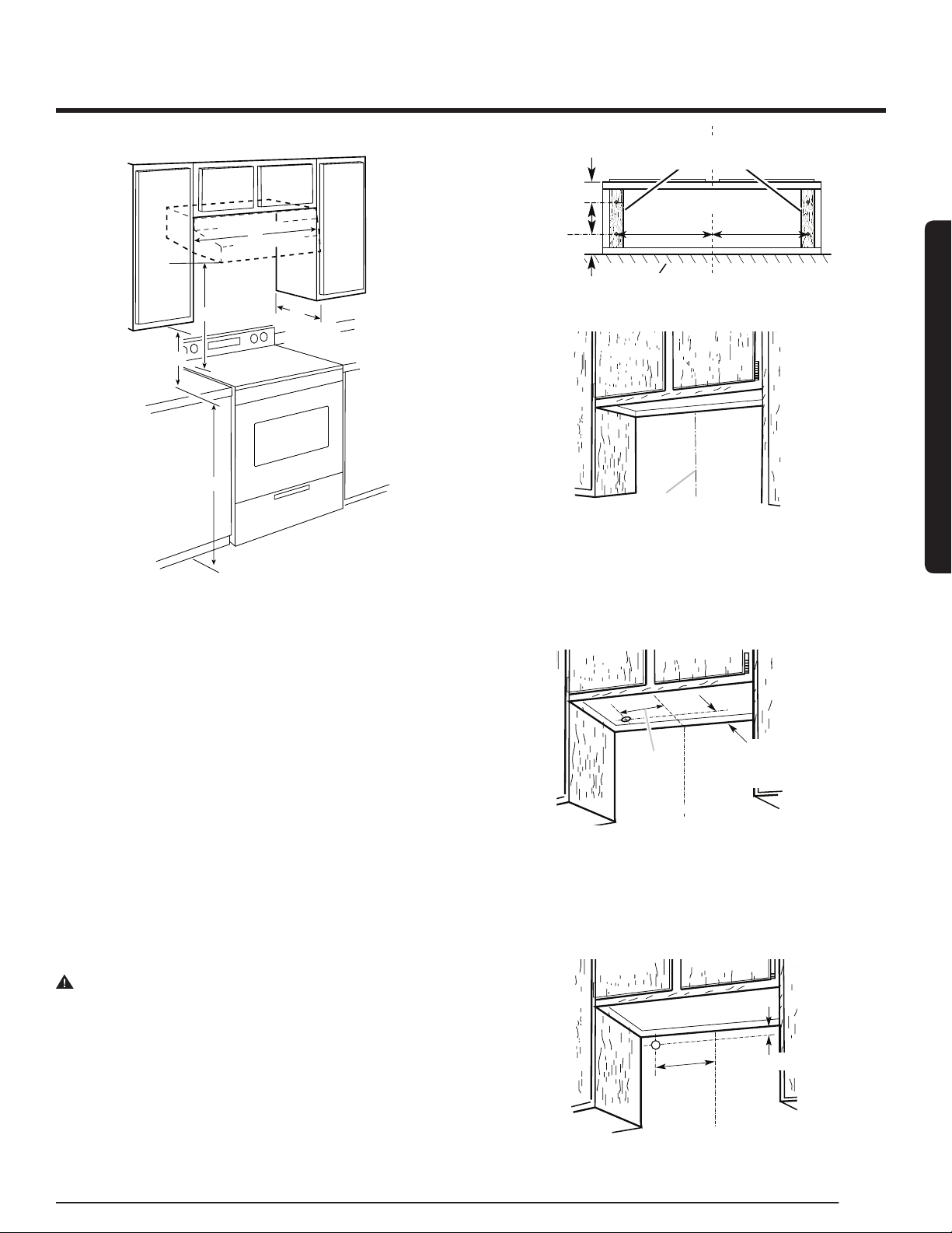
Installation Clearances
C
B
A
E
D
A. 18” (45.7 cm) min. clearance - upper cabinet to countertop
B. 24” (61.0 cm) min. for electric cooking surfaces
27” (68.6 cm) min. for gas cooking surfaces
36” (91.4 cm) suggested max. - bottom of range hood to cooking surface
C. 30” (76.2 cm) or 36” (91.4 cm) min. cabinet opening width
D. 12” (30.5 cm) min. cabinet depth
E. 36” (91.4 cm) base cabinet height
Installation Instructions
We recommend that a qualied technician install the range hood. It is the
installer’s responsibility to ensure the range hood complies with the instal-
lation clearances specified for the product.
Prepare the Location
• We recommend you install the vent system before you install the hood.
• Before making cutouts, make sure there is proper clearance within
the ceiling or wall for vent ttings.
• If the cabinet you are attaching the hood to is not mounted on the wall
yet, it may be easier to attach the cutout to the bottom of the cabinet
before mounting the cabinet on the wall.
1. Disconnect power.
2. Determine which venting method to use: roof or wall.
3. Select a at surface for assembling the range hood.
Place a covering over that surface.
WARNING
EXCESSIVE WEIGHT HAZARD
USE TWO OR MORE PEOPLE T
O MOVE AND INSTALL THE RANGE
HOOD. FAILURE TO DO SO CAN RESULT IN BACK OR OTHER
INJURIES.
4. Using 2 or more people, lift the range hood onto a covered surface.
5. If the cabinet has a recessed bottom, add wood ller strips on each
side to ll in the space. Install screws to attach ller strips in the loca-
tions shown in the illustration at the top of the next column.
NOTE: All the screw locations must be measured from the cabinet’s
centerline.
Wood ller strips
(recessed cabinet
bottoms only)
Cabinet
bottom
Wall
3” (7.6 cm)
CL
30”model: 13
13
⁄16” (35 cm)
36”model: 16
6
⁄8” (42,5 cm)
30”model: 13
13
⁄16” (35 cm)
36”model: 16
6
⁄8” (42,5 cm)
3” (7.6 cm)
6. Determine and clearly mark a vertical centerline on the wall and
cabinet in the area the vent opening will be made.
A
A. Centerline
Determine the wiring hole location
Cut only one 1
1
⁄4” (3.2 cm) diameter wiring access hole.
To wire through the top:
Mark a line Distance “A” (See below) from the left of the centerline on
the underside of the cabinet. Mark a point on this line that is 1
9
⁄16” (4
cm) from the back wall. Drill a 1¼” (3.2 cm) diameter hole through the
cabinet at this point.
A
Centerline
1
9
⁄16” (4 cm)
from wall, not
cabinet frame
Distance A. 12” (30.5 cm) for 30” (76.2 cm) models
12¼” (31.1 cm) for 36” (91.4 cm) models
To wire through the wall:
Mark a line Distance “A” (See below) from the left of the centerline on
the underside of the cabinet. Mark a point on this line that is 1” (2.54
cm) below the bottom of the cabinet. Drill a 1¼” (3.2 cm) diameter hole
through the wall at this point.
Centerline
A
1” (2.5 cm)
Distance A. 12” (30.5 cm) for 30” (76.2 cm) models
12¼” (31.1 cm) for 36” (91.4 cm) models
Installation Requirements
Loading ...
Loading ...
Loading ...