Loading ...
Loading ...
Loading ...
98
ASSEMBLY INSTRUCTIONS
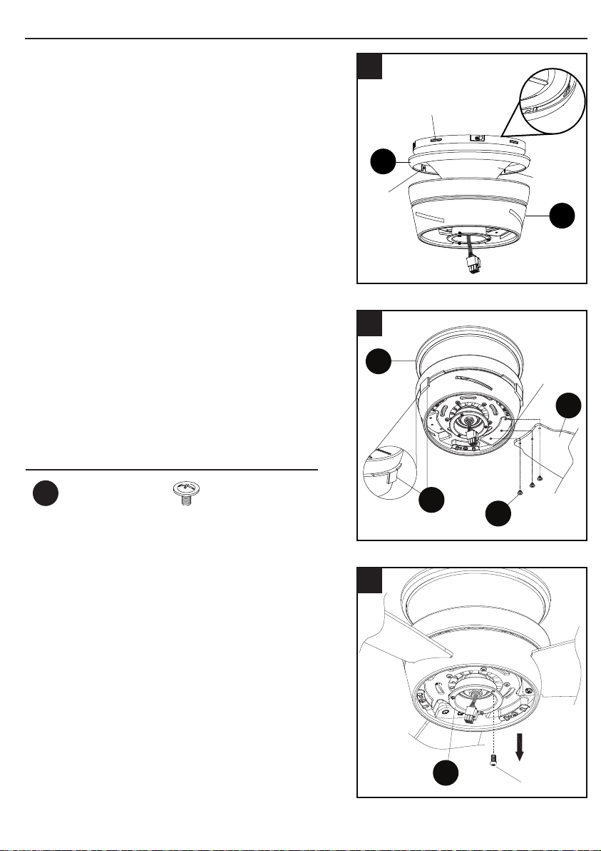
7. Align the notches on the fan motor (B) canopy
with raised areas inside the trim ring (C). Pop
the trim ring (C) into the canopy.
8. Remove and discard preassembled rubber
shipping stabilizer tabs (I) from fan motor (B).
Insert blade (D) into slot on fan motor (B).
Secure blade (D) with three blade screws
(BB). Repeat for remaining blades (D) and
blade screws (BB).
9. Loosen two screws from switch housing
plate (H). Remove and save remaining
screw.
B
C
Canopy
Notch
Raised
area
7
D
BB
I
B
Slot
8
H
Screw
9
ASSEMBLY INSTRUCTIONS
10. Connect the 9-pin plug exiting the bottom of
the fan motor (B) to the 9-pin plug from the
light plate (E). Be sure plugs snap together
completely. Attach light plate (E) to switch
housing plate (H). Align keyholes, then twist to
lock. Replace previously removed screw (Step
9, page 8) and securely tighten all screws.
11. Loosen two preassembled screws from
light plate (E). Remove and save remaining
preassembled screw from light plate (E).
12. Connect the WHITE wire from the light
plate (E) to the WHITE wire from the light
xture (F). Connect the BLUE wire from
the light plate (E) to the BLUE wire from
the light xture (F). Align the keyhole
slots on the light xture and the light
plate (E), and twist to lock. Replace the
previously removed screw (Step 11, page
9) and securely tighten all of the screws.
H
B
E
Keyslot hole
Screw
Female
plug
Male
plug
10
Screw
E
11
Screw
E
F
White
Blue
12
Hardware Used
Blade Screw x 9
BB
Loading ...
Loading ...
Loading ...