Loading ...
Loading ...
Loading ...
8
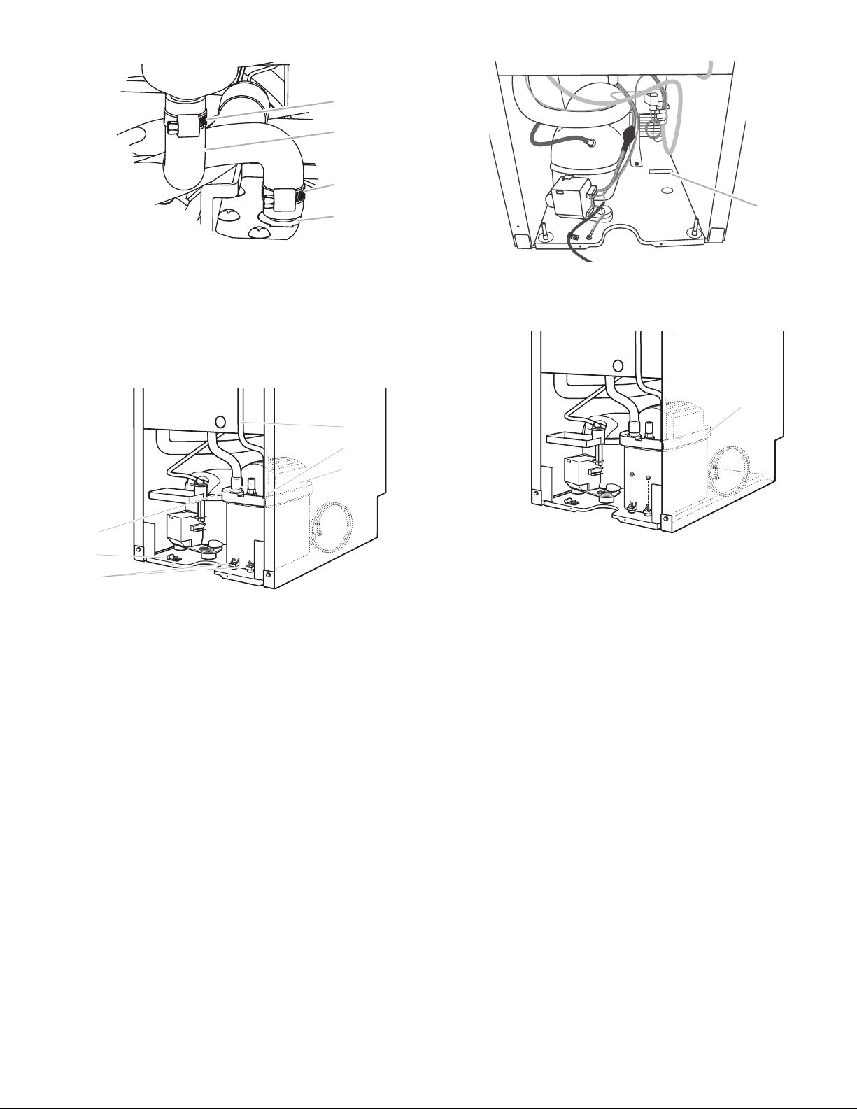
Drain Tube
5. Install vent tube (
5
⁄
16
" ID x 32" [81 cm]) to drain pump reservoir
vent. Use one
5
⁄
8
" small adjustable clamp, supplied. See
“Parts Locations” illustration.
NOTE: Do not install household drain tube at this time.
Parts Locations
6. Remove power cord clamp and ground screw attached to ice
maker power cord, which is mounted to the unit base. See
“Parts Locations” illustration.
NOTE: Clamp and screw will be reused.
7. Slide drain pump into the ice maker base on the right side.
The pump mounting tab should slip into the rectangular slot
in the ice maker base. It will be necessary to tip the pump
slightly to slip into the slot. See “Drain Pump Mounting Tab
Slot” illustration.
Drain Pump Mounting Tab Slot
Drain Pump Installed
8. Align the 2 screw holes at the rear of the pump. Use two
#8-32 x
3
⁄
8
" screws, supplied. See “Parts Locations”
illustration.
9. Connect drain tube to ice maker bin outlet (
5
⁄
8
" ID), using
7
⁄
8
"
adjustable clamp, supplied. See “Drain Tube” illustration.
10. Coil ice maker power cord into a 4" (10.2 cm) diameter
coil. Wrap electrical tape around the power cord in several
places to keep the cord in a coil. Locate coiled power cord
between the drain pump and side of enclosure and plug into
the receptacle of the drain pump. See “Parts Locations”
illustration.
11. Attach the drain pump power cord to ice maker unit base with
clamp and screw (removed in Step 6) that was used to attach
ice maker power cord. See “Parts Locations” illustration.
12. Place new rear panel (small one for 15" ice makers, large one
for 18") against the back of the ice maker. Route the vent tube
and drain pump discharge tube through cutouts in the rear
panel.
13. Secure rear panel with original screws. See “Rear Panel”
illustration.
14. Secure vent tube to back of ice maker using 3 clamps
and three #8-32 x
3
⁄
8
" screws, supplied. See “Vent Tube”
illustration.
A
B
C
D
A.
7
⁄
8
" adjustable hose clamp
B. Drain tube (ice bin to drain pump)
C.
7
⁄
8
" adjustable hose clamp
D. Drain pump reservoir inlet
A
B
D
E
C
G
F
A. Vent tube
B.
5
⁄
8
" hose clamp
C. Drain pump discharge tube
D. Drain pump
E. Ice maker unit power cord
F. #8-32 x
3
⁄
8
" pump mounting screws
G. Drain pump power cord, clamp
andscrew
A
A. Mounting tab slot
A
A. Drain pump installed
Loading ...
Loading ...
Loading ...