Loading ...
Loading ...
Loading ...
7
(1) Valve size for outdoor unit
For liquid ø9.52 mm
For gas ø15.88 mm
(2) Valve size for branch box
A UNIT
Liquid pipe ø6.35 mm
Gas pipe ø9.52 mm
B UNIT
Liquid pipe ø6.35 mm
Gas pipe ø9.52 mm
C UNIT
Liquid pipe ø6.35 mm
Gas pipe ø9.52 mm
D UNIT
Liquid pipe ø6.35 mm
Gas pipe ø9.52 mm
E UNIT
Liquid pipe ø6.35 mm
Gas pipe ø12.7 mm
* 3-branch type : only A, B, C unit
Conversion formula
1/4 F ø6.35
3/8 F ø9.52
1/2 F ø12.7
5/8 F ø15.88
3/4 F ø19.05
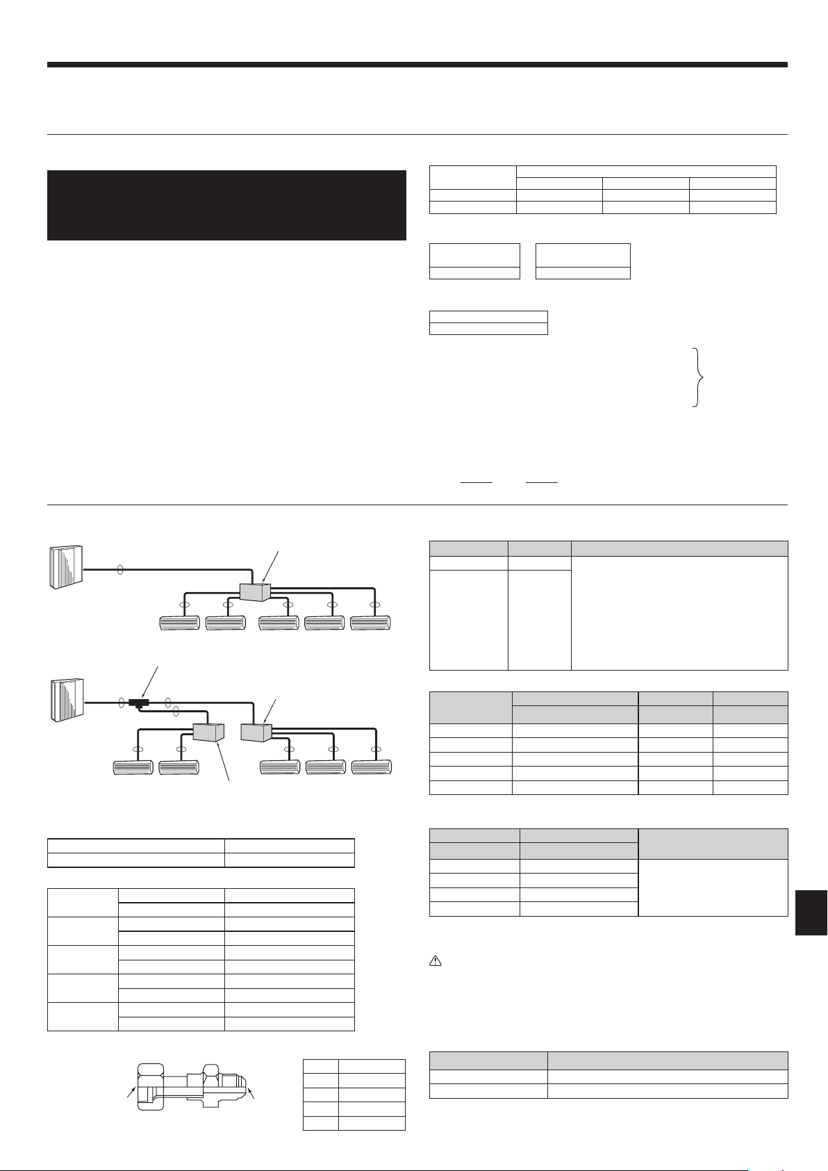
5.4. Selecting pipe size (Fig. 5-2)
Conversion formula
A B
Liquid ø9.52 mm
The piping connection size differs according to
the type and capacity of indoor units. Match the
piping connection size of branch box with indoor
unit.
If the piping connection size of branch box does
not match the piping connection size of indoor
unit, use optional different-diameter (deformed)
joints to the branch box side. (Connect deformed
joint directly to the branch box side.)
Gas ø15.88 mm
Different-diameter joint (optional parts) (Fig. 5-3)
Model name
Connected pipes diameter Diameter A Diameter B
mm mm mm
MAC-A454JP ø9.52 → ø12.7 ø9.52 ø12.7
MAC-A455JP ø12.7 → ø9.52 ø12.7 ø9.52
MAC-A456JP ø12.7 → ø15.88 ø12.7 ø15.88
PAC-493PI ø6.35 → ø9.52 ø6.35 ø9.52
PAC-SG76RJ-E ø9.52 → ø15.88 ø9.52 ø15.88
Piping preparation
1 Table below shows the specications of pipes commercially available.
Outside diameter Insulation thickness
Insulation material
mm mm
6.35 8
Heat resisting foam plastic 0.045
specic gravity
9.52 8
12.7 8
15.88 8
2 Ensure that the 2 refrigerant pipes are insulated to prevent condensation.
3 Refrigerant pipe bending radius must be 100 mm or more.
Caution
Be sure to use the insulation of specied thickness. Excessive thickness may
cause incorrect installation of the indoor unit and branch box, and lack of
thickness may cause dew drippage.
2-branch pipe (Joint) : Optional parts (According to the connection method,
you can choose the favorite one.
Model name Connection method
MSDD-50AR-E are
MSDD-50BR-E brazing
■ Installation procedure (2 branches pipe (Joint))
Refer to the installation manuals of MSDD-50AR-E and MSDD-50BR-E.
A
B B B B B
A
A
A
BBBBB
B
A
5. Installing the refrigerant piping
Fig. 5-2
5.3. Additional refrigerant charge
Additional refrigerant charge
• The necessity of additional refrigerant is determined according to the to-
tal piping length (c1+b1+b2+a1+a2+a3+a4+a5+a6) and the total capacity of
indoor units. Refer to the chart to the right.
• If additional refrigerant is necessary, charge the unit with additional re-
frigerant according to the permitted pipe length in the chart to the right.
In addition, in order to carry out service, enter the size and length of each liquid pipe
and additional refrigerant charge amounts in the spaces provided on the “Refrigerant
amount” plate on the outdoor unit.
Calculation of additional refrigerant charge
• Calculate the additional charge using the liquid pipe size and length of the ex-
tended piping and total capacity of connected indoor units.
• Calculate the additional refrigerant charge using the procedure shown to the
right, and charge with the additional refrigerant.
• For amounts less than 0.1 kg, round up the calculated additional refrigerant
charge.
(For example, if the calculated charge is 2.81 kg, round up the charge to 2.9 kg.)
<Additional Charge>
Necessity of additional charge
Total capacity of
indoor units
Total piping length
0 m – 5 m 6 m – 15 m 16 m –
– 16.0 kW Not necessary Not necessary Necessary
16.1 kW – 20.2 kW * Not necessary Necessary Necessary
* For MXZ-8C140, the capacity is 16.1 – 18.2 kW.
Calculation of refrigerant charge
Pipe size Liquid pipe
+
Pipe size Liquid pipe
–
0.2 kg
ø6.35 ø9.52
(m) × 19.0 (g/m) (m) × 50.0 (g/m)
* For amounts less than 0 kg, use 0 kg.
Included refrigerant amount when shipped from the factory
Included refrigerant amount
8.0 kg
<Example>
Outdoor model : MXZ-8C160VAMD c1 + b1 : ø9.52 30 m
Indoor 1 : model 71 a1 : ø9.52 15 m
2 : model 42 a2 : ø6.35 10 m
3 : model 25 a3 : ø6.35 10 m
4 : model 25 a4 : ø6.35 20 m
The total length of each liquid line is as follows:
ø9.52 : c1 + b1 + a1 = 30 + 15 = 45 m
ø6.35 : a2 + a3 + a4 = 10 + 10 + 20 = 40 m
<Calculation example>
Additional refrigerant charge
40 ×
19.0
+ 45 ×
50.0
– 0.2 = 2.9 (rounded up)
1000 1000
5.2. Pipe length and height difference (Fig. 5-
1)
Flared connections
• This unit has ared connections on each indoor unit and branch box and outdoor
unit sides.
• Remove the valve cover of the outdoor unit, then connect the pipe.
• Refrigerant pipes are used to connect the branch box and outdoor unit.
At the conditions
below:
Fig. 5-3
■ In case of using 2-branch boxes
■ In case of using 1-branch box
Flare connection employed. (No. brazing)
Branch box
Branch box #2
Branch box #1
2 branches pipe (joint)
: optional parts.
BH79D391L03_EN.indd 7 7/17/2015 1:08:18 PM
Loading ...
Loading ...
Loading ...