Loading ...
Loading ...
Loading ...
10
6. Drainage piping work
5. Installing the refrigerant piping
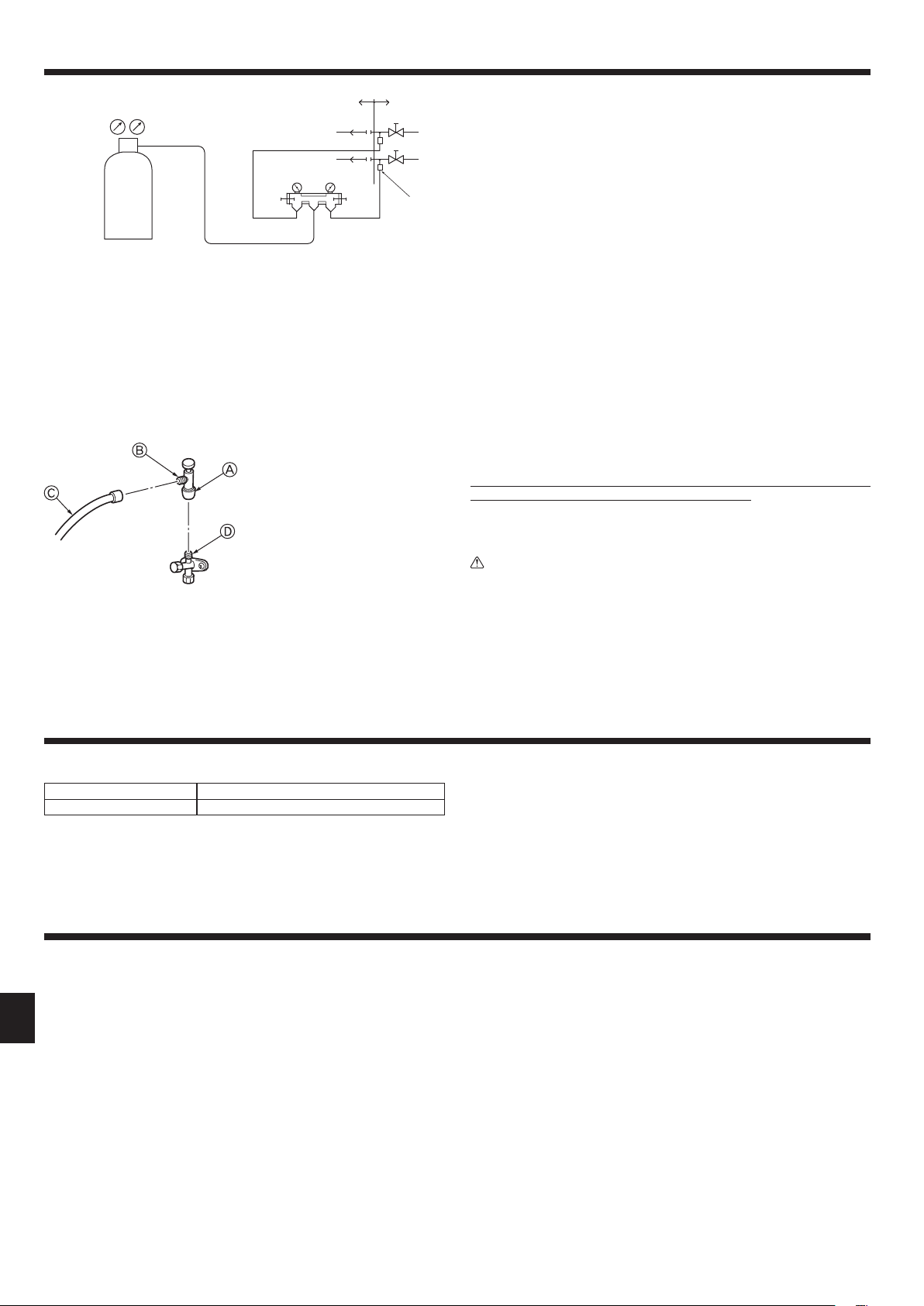
Precautions when using the charge valve (Fig. 5-11)
Do not tighten the service port too much when installing it, otherwise, the valve core
could be deformed and become loose, causing a gas leak.
After positioning section B in the desired direction, turn section A only and tighten it.
Do not further tighten sections A and B together after tightening section A.
Outdoor unit drainage pipe connection
When drain piping is necessary, use the drain socket or the drain pan (option).
Drain socket PAC-SG61DS-E
Drain pan PAC-SH97DP-E
7. Electrical work
* The figure to the left is an example only.
The stop valve shape, service port po-
sition, etc., may vary according to the
model.
* Turn section A only.
(Do not further tighten sections A and
B together.)
C Charge hose
D Service port
LO
HI
A
C D
B
K
E F
G
H
I
Fig. 5-11
Warning:
• When installing the unit, securely connect the refrigerant pipes before
starting the compressor.
Fig. 5-10
7.1. Caution
1 Follow ordinance of your governmental organization for technical standard
related to electrical equipment, wiring regulations and guidance of each electric
power company.
2 Wiring for control (hereinafter referred to as transmission line) shall be (5 cm
or more) apart from power source wiring so that it is not inuenced by electric
noise from power source wiring. (Do not insert transmission line and power
source wire in the same conduit.)
3 Be sure to provide designated grounding work to outdoor unit.
4 Give some allowance to wiring for electrical part box of indoor and outdoor
units, because the box is sometimes removed at the time of service work.
5 Never connect the main power source to terminal block of transmission line. If
connected, electrical parts will be burnt out.
6 Use 2-core shield cable for transmission line. If transmission lines of different
systems are wired with the same multiplecore cable, the resultant poor trans-
mitting and receiving will cause erroneous operations.
7 Only the transmission line specied should be connected to the terminal block
for outdoor unit transmission.
(Transmission line to be connected with indoor unit : Terminal block TB3 for
transmission line, Other : Terminal block TB7 for centralized control)
Erroneous connection does not allow the system to operate.
8 In case to connect with the upper class controller or to conduct group operation
in different refrigerant systems, the control line for transmission is required
between the outdoor units each other.
Connect this control line between the terminal blocks for centralized control.
(2-wire line with no polarity)
When conducting group operation in different refrigerant systems without con-
necting to the upper class controller, replace the insertion of the short circuit
connector from CN41 of one outdoor unit to CN40.
9 Before turning outdoor unit on, be sure to turn the indoor units and the branch
boxes.
5.8. Refrigerant pipe airtight testing method.
Airtight test (Fig. 5-10)
Airtight test should be made by pressurizing nitrogen gas. For the test method, refer
to the following gure.
(1) Connecting the testing tool. Make a test with the stop valve closed. Be also sure
to pressurize both liquid or high-pressure pipe and gas or low pressure pipe.
(2) Do not add pressure to the specied pressure all at once; add pressure little by
little.
1 Pressurize to 0.5 MPa, wait 5 minutes, and make sure the pressure does not
decrease.
2 Pressurize to 1.5 MPa, wait 5 minutes, and make sure the pressure does not
decrease.
3 Pressurize to 4.15 MPa and measure the surrounding temperature and refrig-
erant pressure.
(3) If the specied pressure holds for about one day and does not decrease, the
pipes have passed the test and there are no leaks.
• If the surrounding temperature changes by 1°C, the pressure will change by
about 0.01 MPa. Make the necessary corrections.
(4) If the pressure decreases in steps (2) or (3), there is a gas leak. Look for the
source of the gas leak.
A Nitrogen gas F Outdoor unit
B System analyzer G Stop valve
C Lo-knob H Liquid pipe or high-pressure pipe
D Hi-knob I Gas pipe or low-pressure pipe
E To branch box K Service port
BH79D391L03_EN.indd 10 7/17/2015 1:08:20 PM
Loading ...
Loading ...
Loading ...