Loading ...
Loading ...
Loading ...
11
OC
BC
A B C D E
BC
A B C
RC
ICIC IC IC IC
RC
R
C
R
C
R
C
IC IC
R
C
IC
R
C
R
C
OC
BC
A B C D E
BC
A B C
IC
RC
IC IC
RC
R
C
IC
R
C
IC
R
C
7. Electrical work
7.3. Wiring transmission cables
1 Types of control cables
1. Wiring transmission cables
• Types of transmission cables: Shielding wire CVVS or CPEVS or MVVS
• Cable diameter: More than 1.25 mm
2
• Maximum wiring length: Within 200 m
2. M-NET Remote control cables
Kind of remote control cable Shielding wire (2-core) CVVS, CPEVS or MVVS.
Cable diameter 0.5 to 1.25 mm
2
Remarks
When 10 m is exceeded, use cable with the
same specications as transmission line wiring.
* Connected with simple remote controller.
M1
S
M2
D GA
E
M1
S
M2
TB3TB1 TB7
F
B1 B2
TB1B
C
B
L
N
1 2 3 C
TBD1
A Power source
B Power supply for branch box
C Screw on the electrical component box
D Transmission line
7.2. Control box and connecting position of wiring
(Fig. 7-1)
1. Connect the branch box transmission line to transmission terminal block (TB3),
or connect the wiring between outdoor units or the wiring with the centralized
control system to the centralized control terminal block (TB7).
When using shielded wiring, connect shield ground of the branch box transmis-
sion line to the screw (E or F) and connect shield ground of the line between
outdoor units and the central control system transmission line to the shield (S)
terminal of the centralized control terminal block (TB7) shield (S) terminal. In
addition, in the case of outdoor units whose power supply connector CN41 has
been replaced by CN40, the shield terminal (S) of terminal block (TB7) of the
centralized control system should also be connected to the screw (E or F) using
attached lead wire.
2. Fix power source wiring to terminal box by using buffer bushing for tensile force
(PG connection or the like).
3. The terminal bed (TB1B) is for supplying power to the branch box (230 V. max
6A).
4. The terminal bed (TBD1) is for the input of the DRED signals (DC 12 V, 1 mA).
Caution:
Never connect the transmission line for the branch box or the central control
system transmission line to this terminal bed (TB1B). If the transmission
lines are connected, the indoor unit terminal block, branch box terminal
block or centralized control terminal block could be damaged.
Fig. 7-1
E Screw on the electrical component box
F Screw on the electrical component box
G DRED signal input
3. MA Remote control cables
Kind of remote control cable Sheathed 2-core cable (unshielded) CVV
Cable diameter 0.3 to 1.25 mm
2
Remarks Within 200 m
* Connected with simple remote controller.
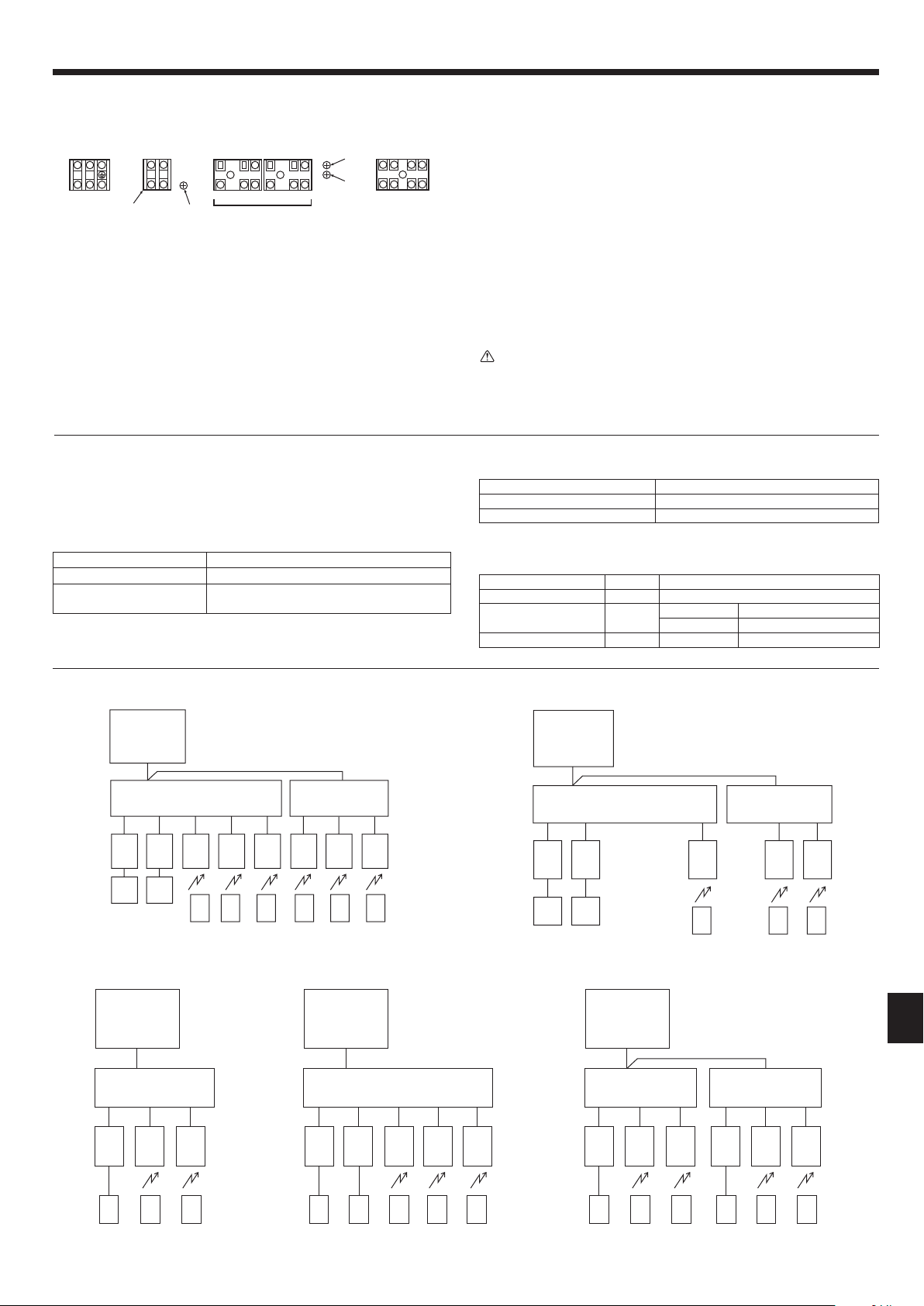
2 Wiring examples
• Controller name, symbol and allowable number of controllers.
Name Symbol Allowable number of controllers
Outdoor unit controller OC –
Indoor unit controller IC
MXZ-8C140 2 to 8 units per 1 OC
MXZ-8C160 2 to 8 units per 1 OC
Remote controller RC MA Maximum of 2 per group
(5-branch type)
(3-branch type)
(5-branch type) (3-branch type)
[1] Basic systems
OC: Outdoor unit
BC: Branch box
IC: Indoor unit
RC: Remote controller
Note:
The indoor units can be connected
to any of the 5 connectors (5-branch
type) or 3 connectors (3-branch type)
of the branch box.
[2] Standard systems
2-1 Only 3-branch type 2-2 Only 5-branch type 2-3 2-branch boxes (3-branch type)
OC
BC
A B C
IC
R
C
IC
R
C
IC
R
C
OC
BC
A B C D E
IC
R
C
IC
R
C
IC
R
C
ICIC
R
C
R
C
OC
BC
A B C
IC
R
C
IC
R
C
IC
BC
A B C
IC
R
C
IC
R
C
IC
R
C
R
C
(3-branch type)
(5-branch type) (3-branch type) (3-branch type)
BH79D391L03_EN.indd 11 7/17/2015 1:08:20 PM
Loading ...
Loading ...
Loading ...