Loading ...
Loading ...
Loading ...
5
3. Installation location
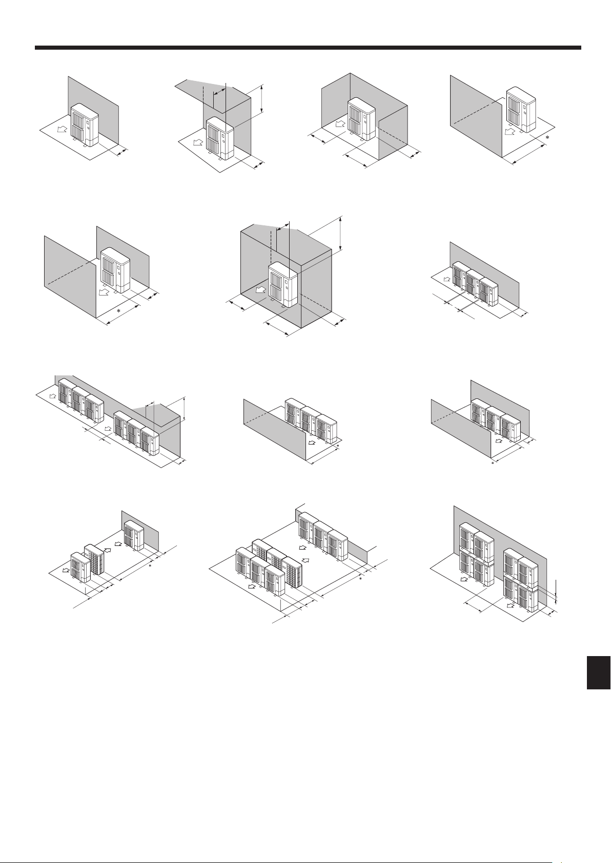
3.5.2. When installing a single outdoor unit
Minimum dimensions are as follows, except for Max., meaning Maximum dimen-
sions, indicated.
Refer to the gures for each case.
1 Obstacles at rear only (Fig. 3-5)
2 Obstacles at rear and above only (Fig. 3-6)
3 Obstacles at rear and sides only (Fig. 3-7)
** To receive the DRED signals for demand control, the clearance is 350 mm or more.
4 Obstacles at front only (Fig. 3-8)
* When using the optional air outlet guides, the clearance is 500 mm or more.
5 Obstacles at front and rear only (Fig. 3-9)
* When using the optional air outlet guides, the clearance is 500 mm or more.
6 Obstacles at rear, sides, and above only (Fig. 3-10)
• Do not install the optional air outlet guides for upward airow.
** To receive the DRED signals for demand control, the clearance is 350 mm or more.
∗∗
∗∗
∗∗∗
∗∗∗
3.5.3. When installing multiple outdoor units
Leave 25 mm space or more between the units.
***
To receive the DRED signals for demand control, the clearance is 350 mm or more.
1 Obstacles at rear only (Fig. 3-11)
2 Obstacles at rear and above only (Fig. 3-12)
• No more than 3 units must be installed side by side. In addition, leave space as shown.
• Do not install the optional air outlet guides for upward airow.
3 Obstacles at front only (Fig. 3-13)
*
When using the optional air outlet guides, the clearance is 1000 mm or more.
4 Obstacles at front and rear only (Fig. 3-14)
* When using the optional air outlet guides, the clearance is 1000 mm or more.
5 Single parallel unit arrangement (Fig. 3-15)
* When using the optional air outlet guides installed for upward airow, the clearance is
1000 mm or more.
6 Multiple parallel unit arrangement (Fig. 3-16)
* When using the optional air outlet guides installed for upward airow, the clearance is
1500 mm or more.
7 Stacked unit arrangement (Fig. 3-17)
• The units can be stacked up to 2 units high.
•
No more than 2 stacked units must be installed side by side. In addition, leave space as shown.
Fig. 3-8Fig. 3-7Fig. 3-6Fig. 3-5
Fig. 3-9 Fig. 3-10 Fig. 3-11
Fig. 3-12
Fig. 3-15 Fig. 3-16 Fig. 3-17
Fig. 3-13 Fig. 3-14
150
1000
1000
200
200
300
Max. 500
1000
150
300
Max. 500
1500
500
250
250
300
500
1500
Max. 300
1500
1500
1500
500
1000
600
2000
150
500
3000
1500
600
1500
800
150
(mm)
BH79D391L03_EN.indd 5 7/17/2015 1:08:17 PM
Loading ...
Loading ...
Loading ...