Loading ...
Loading ...
Loading ...
G
G
Screw
8 9
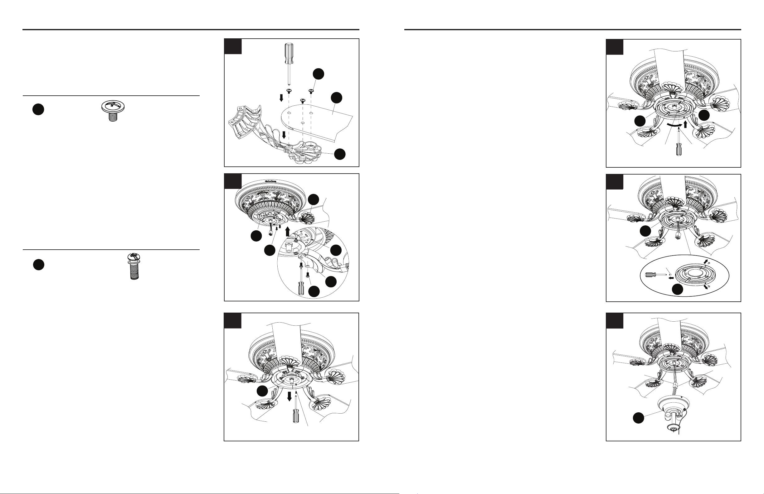
ASSEMBLY INSTRUCTIONS ASSEMBLY INSTRUCTIONS
Hardware Used
7. Attach a blade (F) to a blade bracket (E) using
the blade screws (EE). Tighten each blade
screw (EE) securely. Repeat for the remaining
blades (F).
10. Insert the wires from the motor (B) through the
middle hole in the switch housing (G). Attach
the switch housing (G) to the switch housing
plate (C). Align the keyslot holes and twist to
lock. Replace the screw previously removed
(Step 9, page 8) and tighten all three screws.
8. Align the holes between the blade bracket
(E) and motor (B). Install the blade assembly
to the motor (B) using blade bracket screws
with washers (FF). Tighten each blade bracket
screw with washer (FF) securely. Repeat for the
remaining blade assemblies.
11. Remove the preassembled screws from the
switch housing (G).
F
E
EE
7
Screw
Keyslot
hole
G
C
10
E
E
B
B
FF
FF
8
11
9. Loosen two screws and remove one screw from
the switch housing plate (C).
C
Screw
9
Hardware Used
EE
Blade Screw x 15 + 1 extra
FF
Blade Bracket Screw
with Washer
10 + 1 extra
12. Connect male plug from fan to female plug from
the light kit (H).
Male plug
Female
plug
H
12
Page 8 Page 9
Loading ...
Loading ...
Loading ...