Loading ...
Loading ...
Loading ...
AA
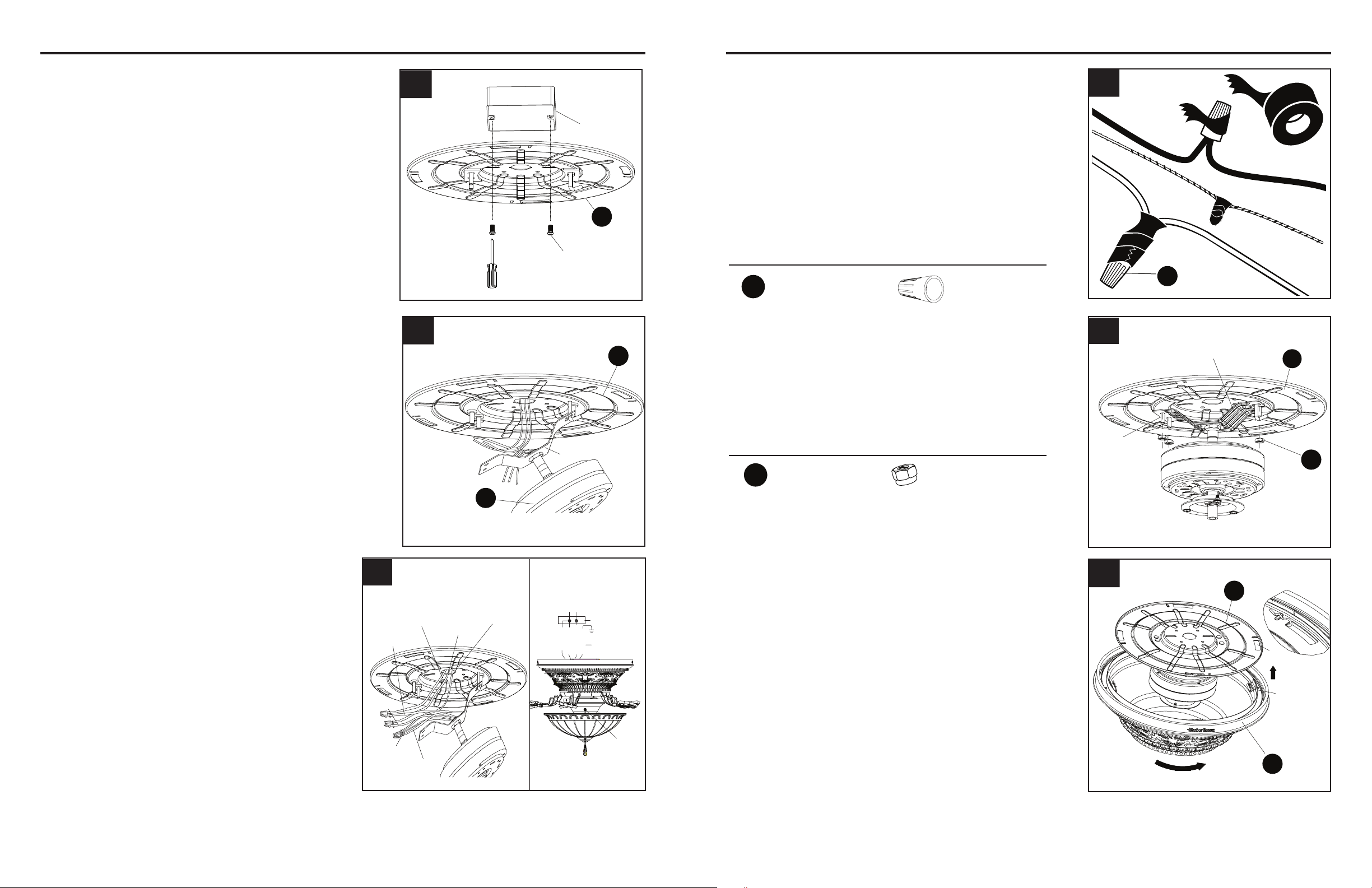
4. Tape the wire connectors (AA) and wires together.
The wires should be spread apart with the
grounded conductor and the equipment-grounding
conductor on one side of the outlet box and the
ungrounded conductor on the other side of the
outlet box. Be sure no bare wire or wire strands are
visible after making connection. Place green and
white connections on opposite side of box from the
black and blue connections. The splices should
be turned upward and pushed carefully up into the
outlet box.
A
Outlet box
Screw
6
7
ASSEMBLY INSTRUCTIONS ASSEMBLY INSTRUCTIONS
NOTE: Black wire is hot power for fan.
Blue wire is hot power for light kit. White
wire is common for fan and light kit. Green
wire is grounded wire. lf house wires are
different colors than referred to above, stop
immediately. A professional electrician is
recommended to determine proper wiring.
1. Securely attach the mounting plate (A) to the
outlet box (not included) using two screws
(supplied with outlet box). Pull the black, white
and grounded wires out of the outlet box
through the hole in the mounting plate (A) and
lay them to the side.
5. Lift the motor bracket so the threaded studs on the
mounting plate (A) protrude through the slots in the
motor bracket. Securely tighten the three lock nuts
(BB) onto the threaded studs.
NOTE: Lightly shake the motor bracket to ensure
the assembly is tight.
2. Carefully lift the motor (B) and engage the slot
in the preassembled bracket with the hook
on the mounting plate (A) so it is securely
suspended.
3. Connect the supply GROUNDED/GREEN wire to
the GREEN/GROUNDED wires from the motor
bracket using the wire connector (AA). Connect
the fan motor WHITE wire to the supply WHITE
wire using the wire connector (AA). Connect the
fan motor BLACK and BLUE wires to the supply
BLACK wire using the wire connector (AA).
E
Threaded
stud
Motor bracket
BB
A
5
Page 6 Page 7
A
B
Bracket
2
1
B
Grounded/
Green
Black
White
Green
Black
Blue
White
outlet box
blue
black
white
green
white
GREEN/
black
Supply circuit
speed
switch
GROUNDED
3
Hardware Used
4
NOTE: Make sure the outlet box is securely
installed in place such that it is able to support
at least the fan weight.
Hardware Used
x 3
Lock Nut
BB
x 3 + 1 extra
Wire Connector
AA
6. Align the four clips on the inside of the motor
housing (D) with the four slots on the outer
edge of the mounting plate (A). Twist the motor
housing (D) clockwise until it stops to hold on
the mounting plate (A).
Clip
Slot
A
D
6
Loading ...
Loading ...
Loading ...