Do not remove spacers (if equipped) on the side walls and/or on the back of the built-in oven. These spacers center the oven in the space provided. The oven must be centered to prevent excess heat buildup that may result in heat damage or fire.
* Suggested distance from floor is 11½" (29.2 cm). Minimum required distance is 4½" (11.4 cm).
NOTES:
Base must be capable of supporting 150 pounds (68 kg) for 27" models and 200 pounds (90 kg) for 30" models
Allow at least 21" (53.3 cm) clearance in front of oven for door depth when it is open.
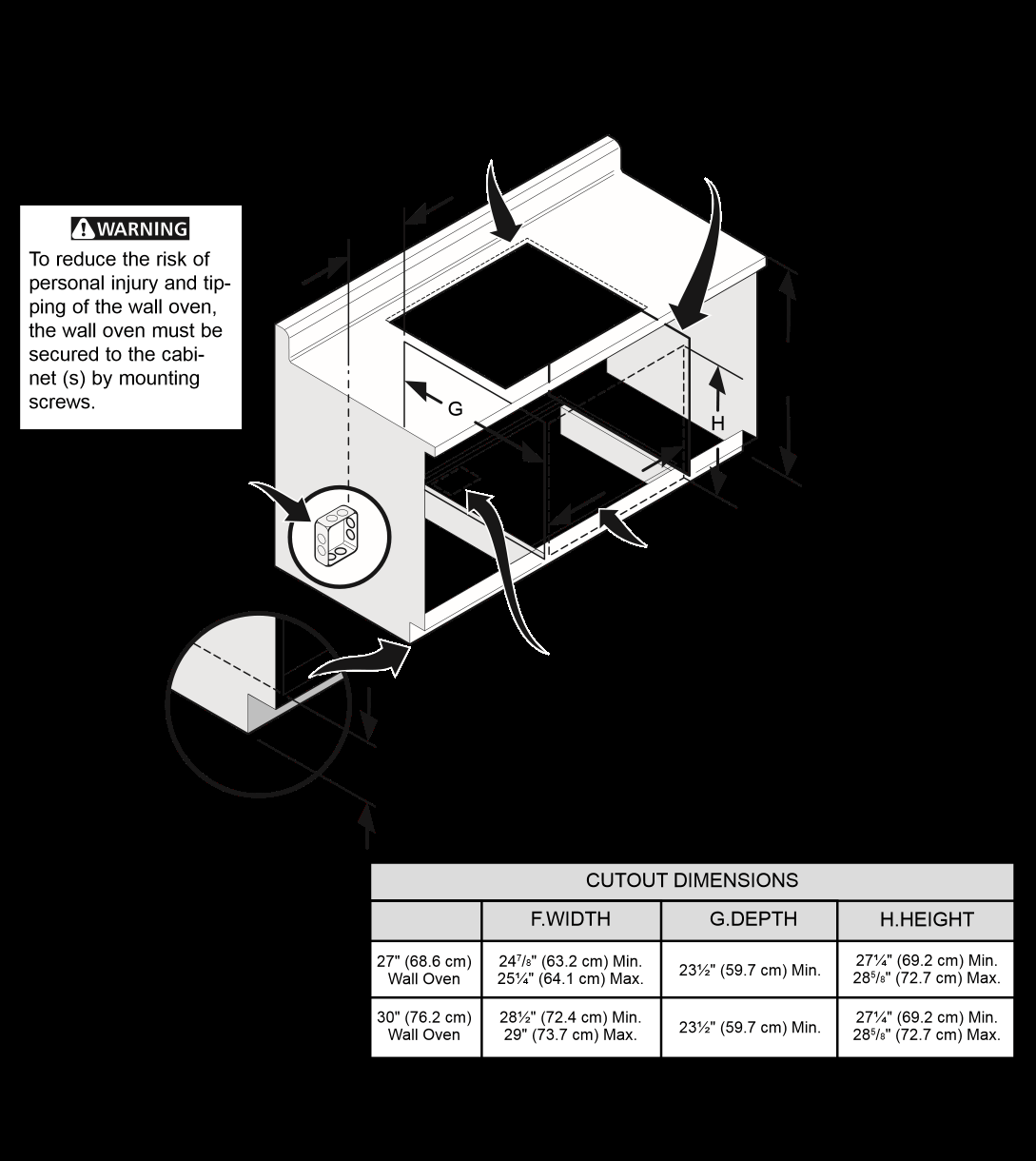
Dimension G (cutout depth) is critical to the proper installation of the built-in oven. If the oven decorative trim does not butt against the cabinet, or if noise is heard on convection models, verify dimension G to assure it is the required depth.
For a cutout height greater than 281 /8" (71.4 cm) add one 2"(5 cm) wide wood shim of appropriate height to each side of the opening under the appliance side rails.
30" MODELS ONLY: For a cutout height (H) greater than 285 /8" (72.7 cm) you can order a larger bottom trim through a Service Center.
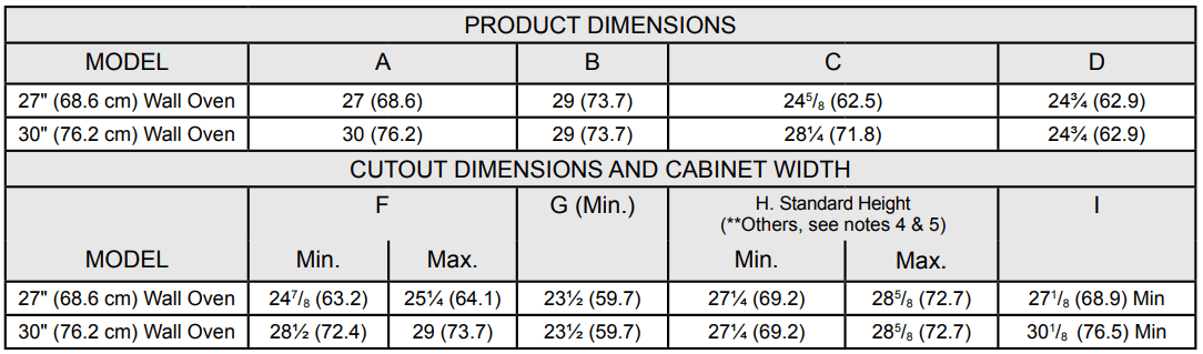
Figure 1: 27" and 30" Single Wall Ovens (Double ovens see Figure 2)
All dimensions are in inches (cm). Printed in United States
Do not remove spacers (if equipped) on the side walls of the built-in oven. These spacers center the oven in the space provided. The oven must be centered to prevent excess heat buildup that may result in heat damage or fire.
NOTES:
Base must be capable of supporting 300 pounds (136 kg) for 27" models and 375 pounds (170 kg) for 30" models.
Allow at least 21" (53.3 cm) clearance in front of oven for door depth when it is open.
Dimension G (cutout depth) is critical to the proper installation of the built-in oven. If the oven decorative trim does not butt against the cabinet, or if noise is heard on convection models, verify dimension G to assure it is according to the required dimension.
For a cutout height greater than 49½" (125.7 cm) add a 2" (5 cm) wide wood shim of appropriate height to each side of the opening under the appliance side rails.
30" MODELS ONLY: For a cutout height (H) greater than 497 /8" (126.7 cm) you can order a larger bottom trim through a Service Center.
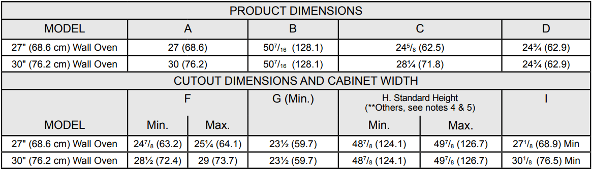
Figure 2: 27" AND 30" DOUBLE OVENS (Single Ovens see Figure 1)
All dimensions are in inches (cm).
Important Notes to the Installer
Read all instructions contained in these installation instructions before installing the wall oven.
Remove all packing material from the oven compartments before connecting the electrical supply to the wall oven.
Observe all governing codes and ordinances.
Be sure to leave these instructions with the consumer.
Oven door may be removed to facilitate installation.
THESE OVENS ARE NOT APPROVED FOR STACKABLE OR SIDE-BY-SIDE INSTALLATION.
Important Note to the Consumer
Keep these instructions with your Owner's Guide for the local electrical inspector's use and future reference.
1. Carpentry
Refer to figure 1 or 2 for the dimensions applicable to your appliance, and the space necessary to receive the oven. The oven support surface may be solid plywood or similar material, however the surface must be level from side to side and from front to rear.
2. Adjusting Oven Height
Oven height can be adjusted with 2" (5cm) wide wood shims when needed to fit into an existing cabinet cutout opening, when cutout height exceeds 281 /8" (71.4cm) for the single wall oven or 49½" (125.7cm) for the double wall oven (see Figure 1 or 2). Place shims of appropriate height beneath the oven side rails.
3. Electrical Requirements
This appliance must be supplied with the proper voltage and frequency, and connected to an individual, properly grounded branch circuit, protected by a circuit breaker or fuse. To know the circuit breaker or fuse required by your model, see the serial plate to find the wattage consumption and refer to table A to get the circuit breaker or fuse amperage.
Observe all governing codes and local ordinances
1. A 3-wire or 4-wire single phase 120/240 or 120/208 Volt, 60 Hz AC only electrical supply is required on a separate circuit fused on both sides of the line (red and black wires). A time-delay fuse or circuit breaker is recommended. DO NOT fuse neutral (white wire). Only certain cooktop models may be installed over certain built-in electric oven models. Approved cooktops and built-in ovens are listed by the MFG ID number (see the insert sheet included in the literature package).
NOTE: Wire sizes and connections must conform with the fuse size and rating of the appliance in accordance with the American National Electrical Code ANSI/NFPA No. 70-latest edition, or with Canadian CSA Standard C22.1, Canadian Electrical Code, Part 1, and local codes and ordinances.
An extension cord should not be used with this appliance. Such use may result in a fire, electrical shock, or other personal injury. If you need a longer power cord you can purchase a 10' (3 m) power cord kit #903056-9010 by calling the Service Center.
2. These appliances should be connected to the fused disconnect (or circuit breaker) box through flexible armored or nonmetallic sheathed cable. The flexible armored cable extending from the appliance should be connected directly to the junction box. The junction box should be located as shown in Figure 1 or Figure 2 and with as much slack as possible remaining in the cable between the box and the appliance, so it can be moved if servicing is ever necessary.
3. A suitable strain relief must be provided to attach the flexible armored cable to the junction box
Electrical Shock Hazard
Electrical ground is required on this appliance.
Do not connect to the electrical supply until appliance is permanently grounded.
Disconnect power to the junction box before making the electrical connection.
This appliance must be connected to a grounded, metallic, permanent wiring system, or a grounding connector should be connected to the grounding terminal or wire lead on the appliance.
Do not use a gas supply line for grounding the appliance.
Failure to do any of the above could result in a fire, personal injury or electrical shock.
In cold weather shipping and storage conditions, make sure that oven is in final location at least three (3) hours before switching on power. Switching on power while oven is still cold may damage the oven controls.
4. Electrical connection
It is the responsibility and obligation of the consumer to contact a qualified installer to assure that the electrical installation is adequate and is in conformance with the National Electrical Code ANSI/NFPA No. 70-latest edition, or with CSA Standard C22.1, Canadian Electrical Code, Part 1, and local codes and ordinances.
Risk of electrical shock (Failure to heed this warning may result in electrocution or other serious injury.) This appliance is equipped with copper lead wire. If connection is made to aluminum house wiring, use only connectors that are approved for joining copper and aluminum wire in accordance with the National Electrical Code and local code and ordinances. When installing connectors having screws which bear directly on the steel and/or aluminum flexible conduit, do no tighten screws sufficiently to damage the flexible conduit. Do not over bend or excessively distort flexible conduit to avoid separation of convolutions en exposure of internal wires.
DO NOT ground to a gas supply pipe. DO NOT connect to electrical power supply until appliance is permanently grounded. Connect the ground wire before turning on the power.
(If your appliance is equipped with a white neutral conductor.)
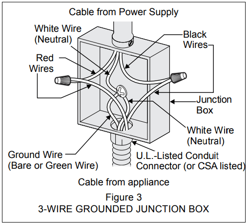
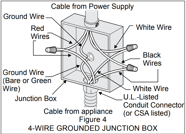
This appliance is manufactured with a white neutral power supply and a frame connected copper wire. The frame is grounded by connection of grounding lead to neutral lead at the termination of the conduit, if used in USA, in a new branch circuit installation (1996 NEC), mobile home, recreational vehicles, where local code do not permit grounding trough the neutral (white) wire or in Canada, disconnect the white and green lead from each other and use ground lead to ground unit in accordance with local codes, connect neutral lead to branch circuit-neutral conductor in usual manner see Figure 4. If your appliance is to be connected to a 3 wire grounded junction box (US only), where local code permit connecting the appliance-grounding conductor to the neutral (white) see Figure 3.
NOTE TO ELECTRICIAN: The armored cable leads supplied with the appliance are UL-recognized for connection to larger gauge household wiring. The insulation of the leads is rated at temperatures much higher than temperature rating of household wiring. The current carrying capacity of the conductor is governed by the temperature rating of the insulation around the wire, rather than the wire gauge alone.
Where local codes permit connecting the appliance grounding conductor to the neutral (white) wire (US Only) (see figure 3):
Disconnect the power supply.
In the junction box:
connect appliance and power supply cable wires as shown in Figure 3.
If oven is used in a new branch circuit installation (1996 NEC), mobile home, recreational vehicle, or where local codes DO NOT permit grounding through the neutral (white) wire, the appliance frame MUST NOT be connected to the neutral wire of the 4-wire electrical system. (see Figure 4):
Disconnect the power supply.
Separate the green (or bare copper) and white appliance cable wires.
In the junction box: connect appliance and power supply cable wires as shown in Figure 4.
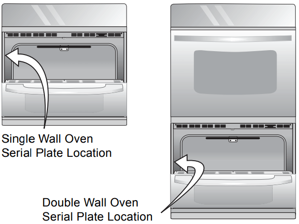
Model and Serial Number Location The serial plate is located along the interior side trim of the oven and visible when the door is opened. When ordering parts for or making inquires about your oven, always be sure to include the model and serial numbers and a lot number or letter from the serial plate on your oven.
5. Cabinet Installation
IMPORTANT: Do not lift the oven by the door handle.
Heavy Weight Hazard
• Use 2 or more people to move and install wall oven. • Failure to follow this instruction can result in injury or damage to the unit.
1. Unpack the wall oven. Remove the bottom trim taped on the oven side panel.
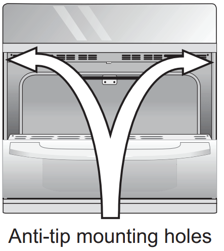
2. Find the 2 anti-tip mounting screws included in the literature package.
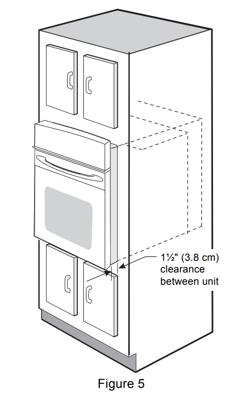
3. Insert the oven into the cabinet opening. Slide oven inward leaving 1½" (3.8 cm) clearance between the oven and front of cabinet (see Figure 5).
4. Pull the armored cable through the hole for it in the cabinet and toward the junction box while moving the appliance inward.
5. Push the oven in and against the cabinet.
6. Install the Anti-tip Mounting Screws
The wall oven can tip when the door is open. The anti-tip mounting screws supplied with the wall oven must be installed to prevent tipping of the wall oven and injury to persons.
A. The mounting holes in the side trims may be used as a template to locate the appliance mounting screw holes (see Figure 6).
B. Use the two screws supplied to fix the appliance to the cabinet.
Tip Over Hazard
• A child or adult can tip the oven and be killed.
• Install the anti-tip device to oven and/or structure per installation instructions.
• Ensure the anti-tip device is re-engaged when the oven is moved.
• Do not operate the oven without the anti-tip device in place and engaged.
• Failure to follow these instructions can result in death or serious burns to children and adults.
Refer to the installation instructions supplied with your appliance for proper installation.
Check for proper installation with a visual check that the anti-tip screws are present. Test the installation with light downward pressure on the open oven door. The oven should not tip forward.
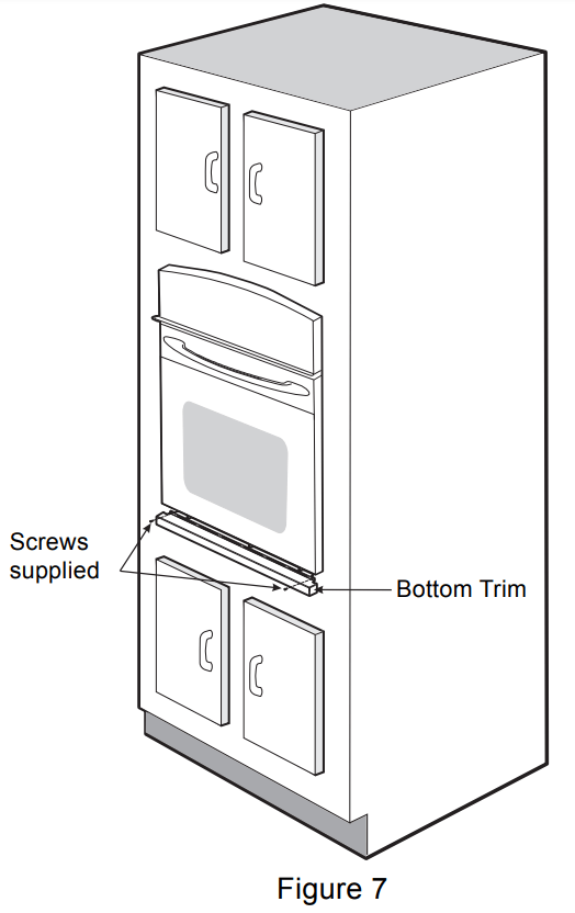
7. Install the Bottom Trim
IMPORTANT: Bottom trim must be installed for the oven to function properly. DO NOT operate the oven without the bottom oven trim installed.
Place the top of the bottom trim over the side trim tabs on each side of the oven below the oven door and fix it using the 2 screws supplied in the mounting holes located on each side trim below the oven frame (see Figure 7).
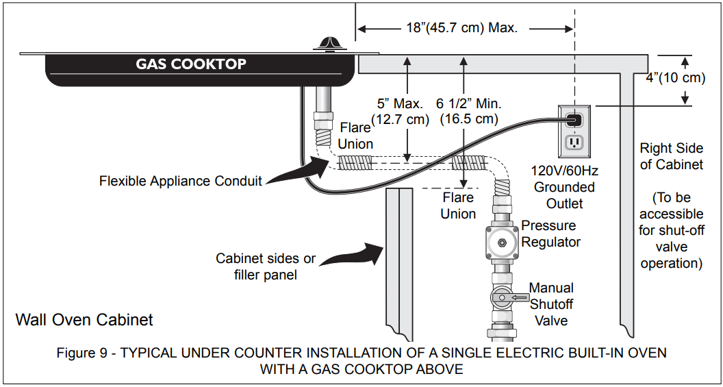
For typical under counter installation of an electric built-in oven see Figure below.
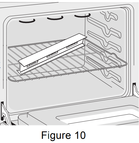
6. Leveling the Wall Oven
Install an oven rack in the center of the upper oven (see Figure 10).
Place a level on the rack. Take 2 readings with the level placed diagonally in one direction and then the other. Use wood shims under the wall oven to level if necessary.
Repeat in the lower oven if you have a double cavity wall oven. If the level indicates that the rack is not level, use wood shims to reach a compromise for both ovens.
IMPORTANT NOTE: A cooling fan inside the upper rear part above the oven (some models) provides cooling of the oven electrical and electronic components. If the oven has been operating at high temperatures, the fan will continue to run after the oven is turned off.
7. Checking Operation
Your model is equipped with an Electronic Oven Control. Each of the functions has been factory checked before shipping. However, it is suggested that you verify the operation of the electronic oven controls once more. Refer to the Use and Care Guide for operation.
Remove all items from the inside of the oven.
Turn on the power to the oven (Refer to your Use & Care Guide.)
Verify the operation of the electronic oven controls:
Bake– Verify that this function makes the oven hot. 20 seconds after turning oven on, open the door and you should feel heat coming from the oven.
Broil– When the oven is set to BROIL, the upper element in the oven should become red.
Convection (some models)–When the oven is set for a convection baking or roasting, both elements cycle on and off alternately and the convection fan will run. The convection fan will stop running when the oven door is opened.
Before You Call for Service
Read the "Before You Call for Service Checklist" and the "Operating Instructions" in your Use and Care Guide. It may save you time and expense. The list includes common occurrences that are not the result of defective workmanship or materials in this appliance.
 Do not remove spacers (if equipped) on the side walls and/or on the back of the built-in oven. These spacers center the oven in the space provided. The oven must be centered to prevent excess heat buildup that may result in heat damage or fire.
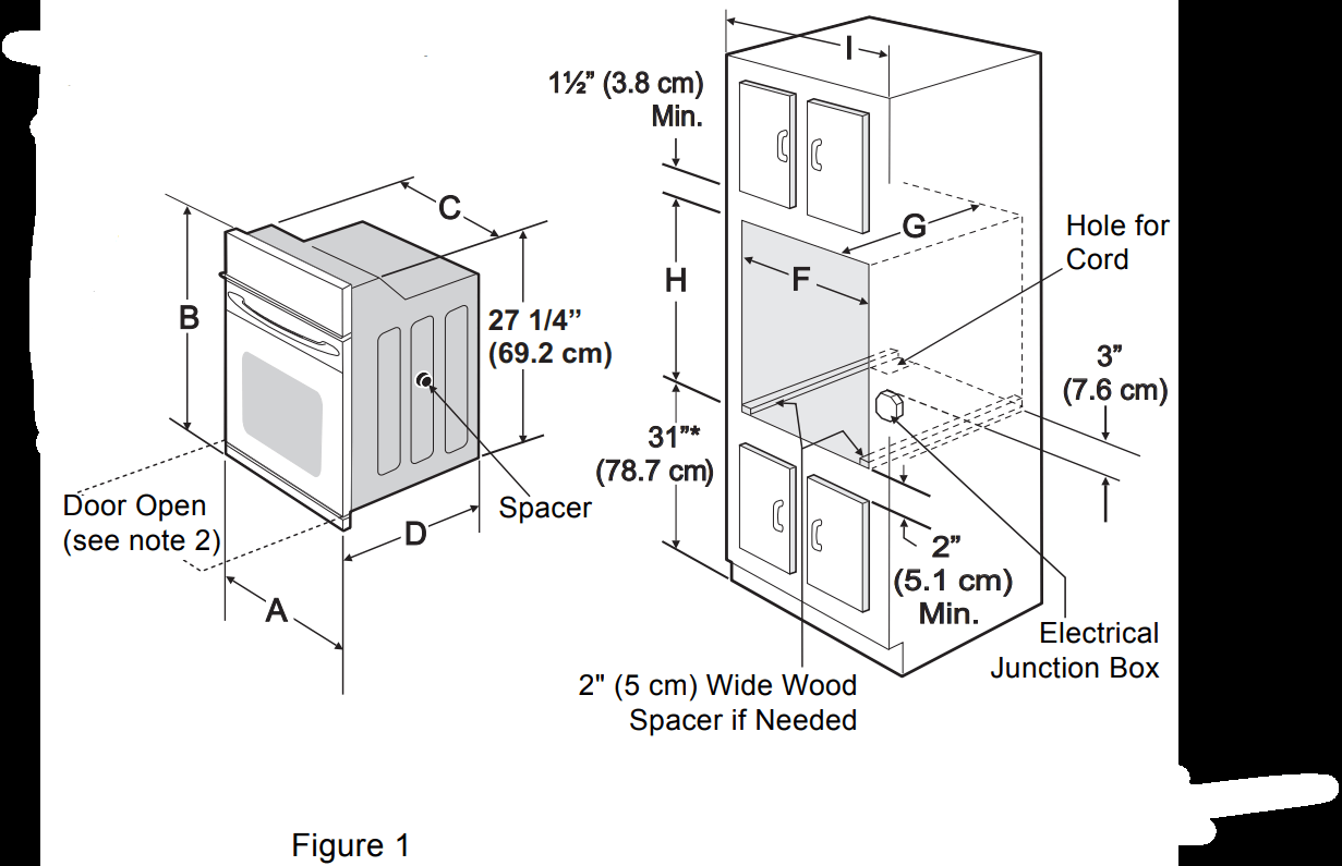


 In cold weather shipping and storage conditions, make sure that oven is in final location at least three (3) hours before switching on power. Switching on power while oven is still cold may damage the oven controls.