
1
D
A
B
F
E
C
GENERAL INFORMATION
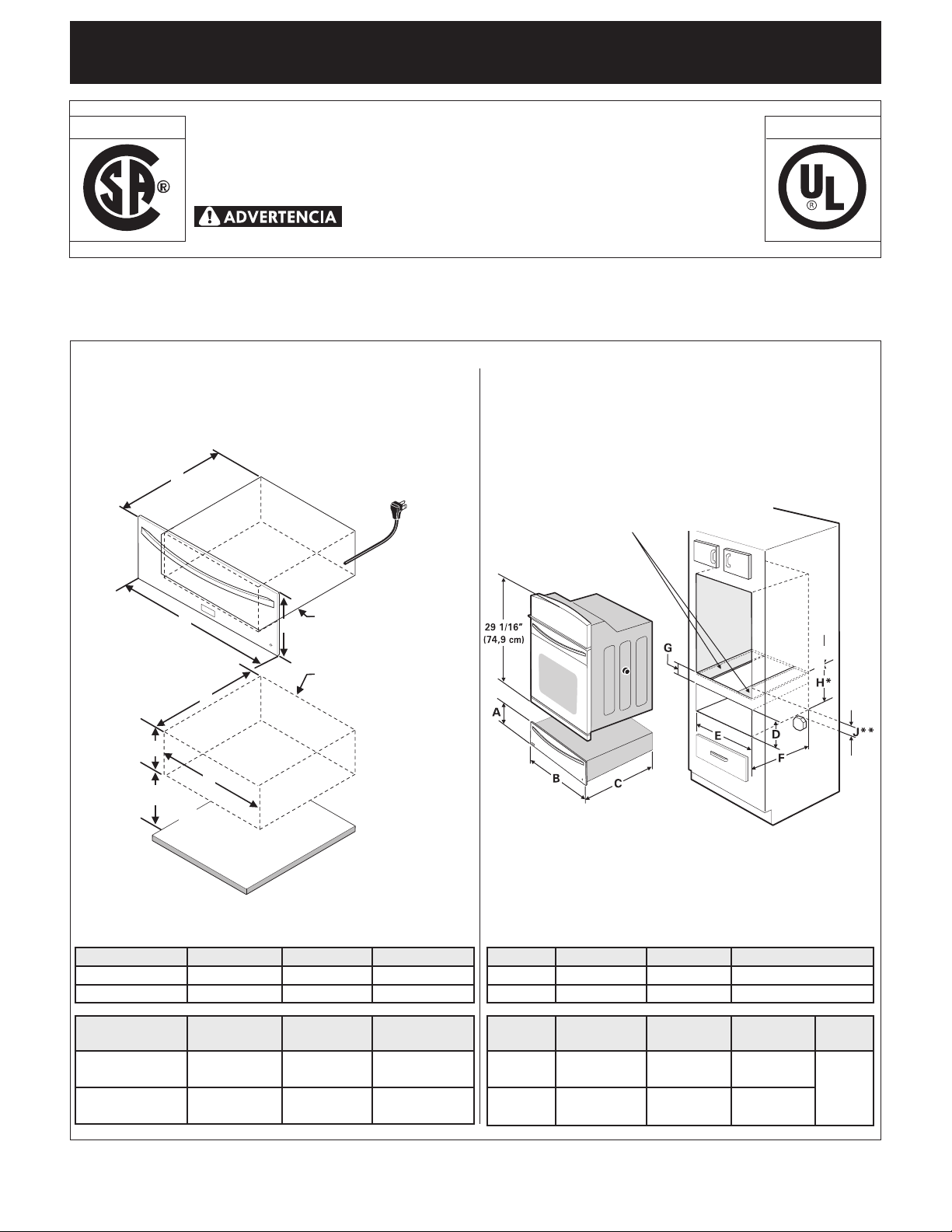
The Warm & Serve Drawer can be used:
• Asastandaloneappliance
• Asacombination27"or30"Warm&ServeDrawerwith
a27"or30"(76cm)built-inovenmountedabove.
IMPORTANT:Thewarmerdrawermustbe
installedonasurfacethatisleveledfrom
lefttoright,reartofront,andiscapable
ofsupporting100lbs(45Kg).
P/N318201823(1004)Rev.A
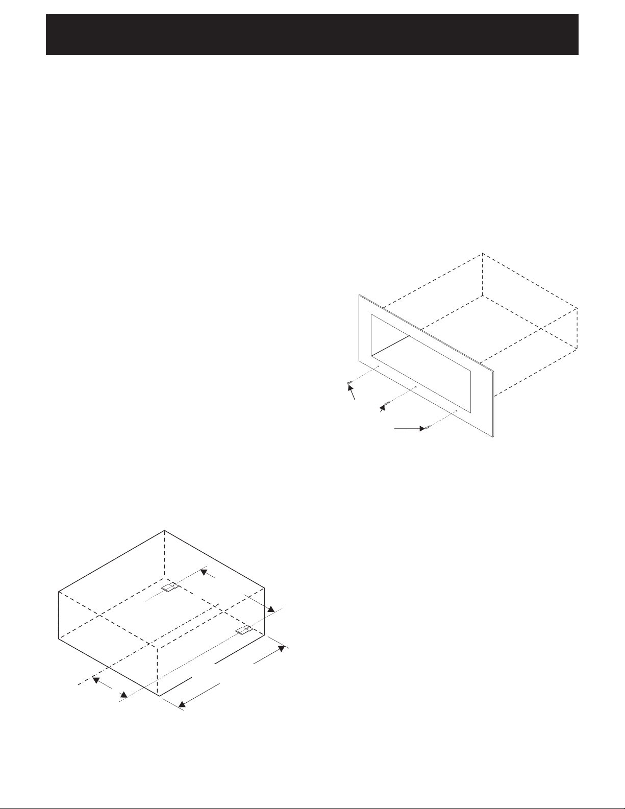
Combination Warm & Serve Drawer/
27" or 30" (76 cm) Built-in Oven Installation
NOTE:A60"(152cm)longcableissuppliedwith
theWarm&ServeDrawer.
FLOOR
Warm&ServeCutout
Warm & Serve Drawer
60" (152 cm) Cord
Minimumdistanceto
oor4½"(11.4cm)
IMPORTANT:TheWarm&ServeDrawerrunsoa
singlephasethree-wire120volt,60hertz,AConly
electricalsupplywithground.
H*=11-7/8"(30,2cm)Min.isthe
spacebetweenthebottomofthewarmerdrawercutoutand
thebottomoftheovencutout.Thisisacriticaldimension
andmustbeprovided.
J**=3"(7.6cm)Max.ElectricalJunctionBoxforwalloven
mustbelowerthanwarmerdrawercutout.
Bottomofovencutout
CAUTION:Installtwo3"(7.6cm)
widex3.4"(1.9cm)thickplanks
capableofsupporting200lbs
(90.7Kg)
PrintedintheUSA
WARM & SERVE DRAWER INSTALLATION INSTRUCTIONS
INSTALLATION AND SERVICE MUST BE PERFORMED
BY A QUALIFIED INSTALLER.
IMPORTANT: SAVE FOR LOCAL ELECTRICAL INSPECTOR'S USE.
READ AND SAVE THESE INSTRUCTIONS FOR FUTURE REFERENCE.
FOR YOUR SAFETY:Donotstoreorusegasolineorother
ammablevaporsandliquidsinthevicinityofthisoranyotherappliance.
Canada
United States
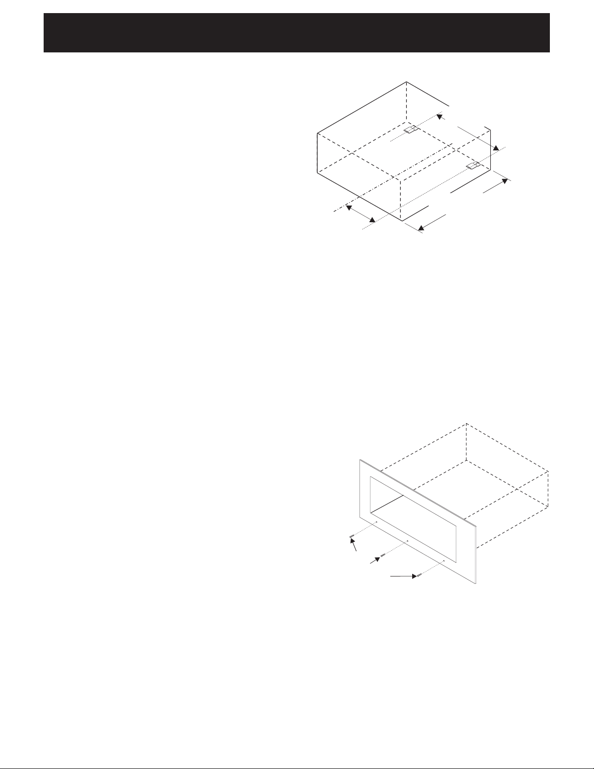
Warm & Serve Drawer Dimensions
Stand Alone Installation
A. HEIGHT B. WIDTH C. DEPTH
27" Models 11¼" (28.6 cm) 27" (68.6 cm) 23 3/8" (59.4 cm)
30" Models 11¼" (28.6 cm) 30" (76.2 cm) 23 3/8" (59.4 cm)
D. CUTOUT
HEIGHT
E. CUTOUT
WIDTH
E. CUTOUT
DEPTH
27" Models Min
.
9 7/8" (25.1 cm)
25½" (64.8 cm)
23 5/8" (60cm)
Max. 10¼" (26 cm)
25¾" (65.4 cm)
24" (61 cm)
30" Models Min. 9 7/8" (25.1 cm)
28½" (72.4 cm)
23 5/8" (60cm)
Max. 10¼" (26 cm)
28¾" (73 cm)
24" (61 cm)
A. HEIGHT B. WIDTH C. DEPTH
27" Models
11¼" (28.6 cm) 27" (68.6 cm)
23 3/8" (59.4 cm)
30" Models
11¼" (28.6 cm) 30" (76.2 cm)
23 3/8" (59.4 cm)
D. CUTOUT
HEIGHT
E. CUTOUT
WIDTH
E. CUTOUT
DEPTH
G.
HEIGHT
27" Min
.
9 7/8" (25.1 cm) 25½" (64.8 cm) 23 5/8" (60cm) 2" (5.1 cm)
Depends
on critical
dimension
H
Max.
10¼" (26 cm) 25¾" (65.4 cm) 24" (61 cm)
30" Min.
9 7/8" (25.1 cm) 28½" (72.4 cm) 23 5/8" (60cm)
Max.
10¼" (26 cm) 28¾" (73 cm) 24" (61 cm)
2
c
/
c
25
5
/
16
"
(64.3 cm)
24"(64.3cm)Max.
23
5
/
8
"(60cm)Min.
c
/
c
12
21
/
32
"
(32.15cm)
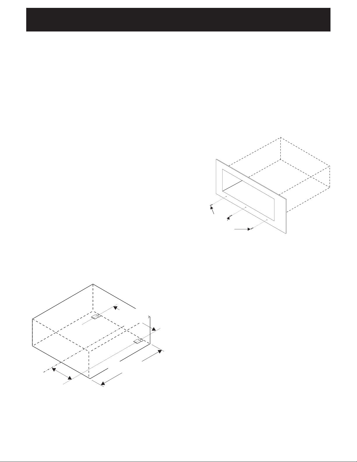
Figure1
Important Notes to the Installer
1. Readallinstructionscontainedintheseinstallation
instructionsbeforeinstallingappliance.
2. Removeallpackingmaterialfromappliancebefore
connectingtheelectricalsupply.
3. Observeallgoverningcodesandordinances.
4. Besuretoleavetheseinstructionswiththe
consumer.
Important Note to the Consumer
Keeptheseinstructionsforfuturereference.
IMPORTANT SAFETY
INSTRUCTIONS
• Besureyourapplianceisinstalledandplugged
intoa120Voltgroundedoutlet.
• Thisappliancemustbeelectricallygroundedin
accordance with the National Electrical Code
ANSI/NFPA No. 70—latest edition in the United
States, or CSA C22.1, Part 1 in Canada, and local
code requirements.
Tools You Will Need
Phillips®Screwdriver,
Pencil
RulerorTapeMeasureandStraight-edge
HandSaworSaberSaw
SpiritLevel
Warm & Serve Drawer Installation
1.Locatethe2anti-tipbracketssuppliedasshownin
gure1.
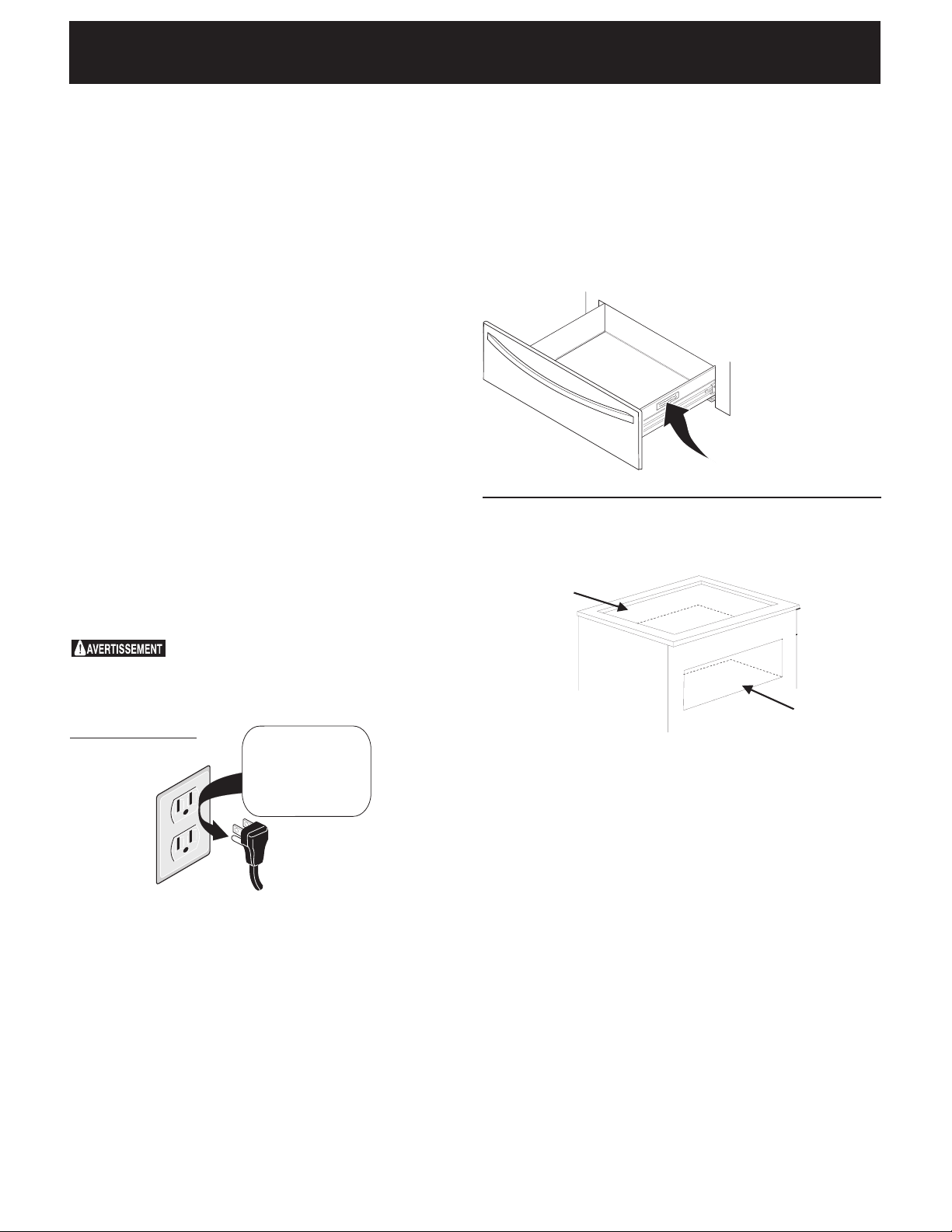
Figure2
Usescrews
suppliedtoattach
drawertofrontof
cabinet.
WARM & SERVE DRAWER INSTALLATION INSTRUCTIONS
2.Slidedrawerintocutoutopeninguntilfrontframeof
drawerisushagainstcabinet.Becarefulnottopinch
electricalcord.
3.RemovethedrawerasinstructedintheUse&Care
Guideandsecuredrawerhousingtocabinetusingthe
3nickel-platedscrewssupplied(seeFigure2).Donot
overtightenscrews.
4.The60"(152cm)appliancepowercordcannowbe
connectedintothe120Voltoutlet.
5.Proceedwithmountingbuilt-inovenabovethe
drawer(ifapplicable).Followinstallationinstructions
providedwithbuilt-inoven.Makesuretouseanti-tip
bracketssuppliedwiththebuilt-inoven.
3
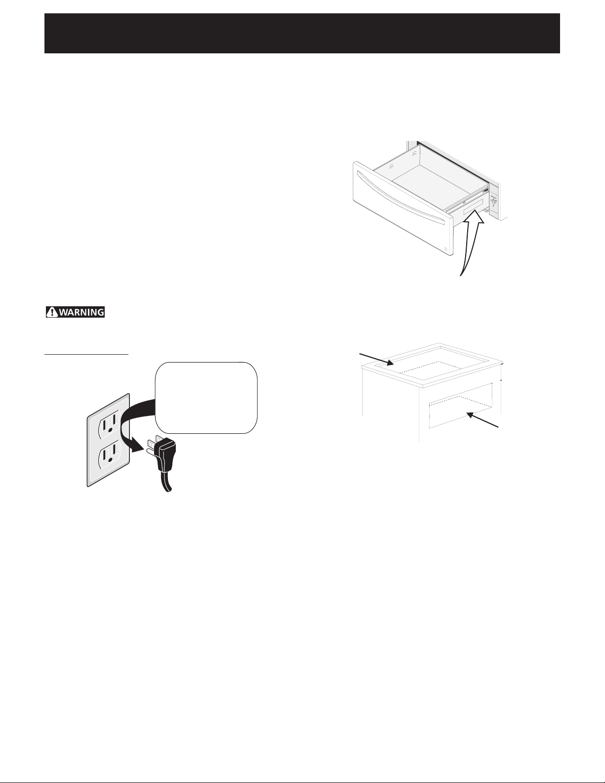
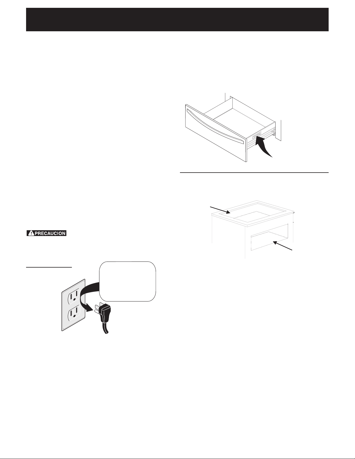
Model and Serial Number Location
Theserialplateislocatedasshownbelow.
Whenorderingpartsforormakinginquiriesaboutyour
Warm&ServeDrawer,alwaysbesuretoincludethe
modelandserialnumbersandalotnumberorletter
fromtheserialplate.
Serial Plate Location
WARM & SERVE DRAWER INSTALLATION INSTRUCTIONS
Combination Warm & Serve Drawer
and Cooktop Installation
A
Youcaninstallthewarmerdrawerincombination
withanelectricorgascooktop.Youmustfollowthe
specicationsfromtheinstallationinstructionsofthe
cooktoptoavoidinterferencewiththegasorelectric
installation.
Cooktop
Cutout
Warmer
Drawer
Cutout
Electrical connection
IMPORTANTPleasereadcarefully.
Forpersonalsafety,thisappliancemustbeproperly
grounded.
Thepowercordofthisapplianceisequippedwitha
3-prong(grounding)plugwhichmateswithastandard
3-pronggroundingwallreceptacletominimizethe
possibilityofelectricshockhazardfromtheappliance.
Thewallreceptacleandcircuitshouldbecheckedby
aqualiedelectriciantomakesurethereceptacleis
properlygrounded.
Whereastandard2-prongwallreceptacleisinstalled,
itisthepersonalresponsibilityandobligationofthe
consumertohaveitreplacedbyaproperlygrounded
3-prongwallreceptacle.
Donot,underanycircumstances,cutorremovethethird
(ground)prongfromthepowercord.
Disconnectelectricalsupplycordfrom
wallreceptaclebeforeservicingcooktop.
Preferred Method
Groundingtype
wallreceptacle
Donot,underany
circumstances, cut,
remove,orbypass
thegrounding
prong.
Powersupplycordwith
3-pronggroundingplug.

4
NOTES
5
D
A
B
F
E
C
INSTRUCCIONES DE INSTALACIÓN PARA EL CAJÓN CALENTADOR
Dimensiones del cajón calentador
Instalación de la combinación cajón
calentadoryhornode30"(76cm)integrado
IMPORTANTE:Elcajóncalentadorfuncionacon
unsuministrodeenergíaeléctricadecorriente
alterna,detrescables,deunasolafase,de120
voltios,60hertzconlíneaatierra.
Piso
Abertura del Cajón
calentador
Cajón Calentador
Cable de 60"
(152 cm)
DistanciaMínima
delpiso41/2"
(11.4cm)
P/N318201823(1004)Rev.A
Precaución:Dostablasde3"(7.6cm)por
3/4"(1.9cm)necesitanserinstaladasy
deberánsoportar200libras(90.7Kg)
Parteinferior
delhorno
H*=11-7/8"(30.2cm)Min.esunadimensióncríticay
necesitaserrespetada.
Impreso en los EUA
J**=3"(7.6cm)Máx.LaCajaparalasconexiones
eléctricasparaelhornodeempotrepuedeestardebajo
delaaberturadelcajóncalentador.
INFORMACIÓN GENERAL -Elcajóncalentador
puedeserusadocomounidadindependienteoen
unacombinaciónentreelcajóncalentadoryel
hornointegradoymontadoporencimadelcajón
LA INSTALACIÓN Y EL SERVICIO DEBEN SER EFECTUADOS POR
UN INSTALADOR CALIFICADO.
IMPORTANTE: GUARDE ESTAS INSTRUCCIONES PARA USO DEL
INSPECTOR LOCAL DE ELECTRICIDAD. LEA Y GUARDE ESTAS
INSTRUCCIONES PARA REFERENCIA FUTURA.
PARASUSEGURIDAD:Noalmacenéniutilicegasolinauotros
vaporesylíquidosinamablesenlaproximidaddeesteodecualquierotroartefacto.
Canadá Estados Unidos
IMPORTANTE:Elcajóncalentadordebedeestarinstalado
conunasuperciellana,delaizquierdaaladerecha,dela
partedeatrásalfrente.Lasuperciedebepodersostener
100libras(45,4Kg).
A. ALTO B. ANCHO C. LARGO
Modelos 27" 11¼" (28.6 cm) 27" (68.6 cm) 23 3/8" (59.4 cm)
Modelos 30" 11¼" (28.6 cm) 30" (76.2 cm) 23 3/8" (59.4 cm)
D. ALTURA DE
LA ABERTURA
E. ANCHO DE
LA ABERTURA
E. LARGO DE
LA ABERTURA
Modelos 27" Min
.
9 7/8" (25.1 cm)
25½" (64.8 cm)
23 5/8" (60cm)
Max
.
10¼" (26 cm)
25¾" (65.4 cm)
24" (61 cm)
Modelos 30" Min. 9 7/8" (25.1 cm)
28½" (72.4 cm)
23 5/8" (60cm)
Max
. 10¼" (26 cm)
28¾" (73 cm)
24" (61 cm)
A. ALTO B. ANCHO C. LARGO
Modelos 27"
11¼" (28.6 cm) 27" (68.6 cm)
23 3/8" (59.4 cm)
Modelos
30"
11¼" (28.6 cm) 30" (76.2 cm)
23 3/8" (59.4 cm)
D. ALTURA DE
LA ABERTURA
E. ANCHO DE
LA ABERTURA
E. LARGO DE
LA ABERTURA
G.
ALTO
27" Min
.
9 7/8" (25.1 cm) 25½" (64.8 cm) 23 5/8" (60cm) 2" (5.1 cm)
Depende
de la
dimensión
críticaH
10¼" (26 cm) 25¾" (65.4 cm) 24" (61 cm)
30" Min
.
9 7/8" (25.1 cm) 28½" (72.4 cm) 23 5/8" (60cm)
Max
.
10¼" (26 cm) 28¾" (73 cm) 24" (61 cm)
Instalación de la unidad independiente
NOTA:Uncablede60"(152cm)delargoes
suministradoconelcajóncalentador.
6
INSTRUCCIONES DE INSTALACIÓN PARA EL CAJÓN CALENTADOR
Notas importantes para el instalador
1.Leatodaslasinstruccionesdeinstalaciónantesde
instalarelelectrodoméstico.
2.Retiretodoslosmaterialesdeempaquedelelectrodoméstico
antesdeconectarlafuentedeenergía.
3.Observetodosloscódigosyleyesdelgobierno
4.Asegúresededejarleestasinstruccionesalconsumidor.
Nota importante para el consumidor
Guardeestasinstruccionesparafuturareferencia.
INSTRUCCIONES
IMPORTANTES DE SEGURIDAD
• Asegúresedequesuelectrodomésticoestáinstalado
yconectadoenuntomacorrientede120voltioscon
tierra.
• Esteelectrodomésticodebeserpuesto
eléctricamenteatierradeacuerdoconelCódigo
Nacional Eléctrico ANSI/NFPA No 7— de la
últimaedicióndelosEstadosUnidos,olaCSA
C22.1,Parte1enCanadá,yconlosrequisitosde
códigoslocales.
Herramientas que usted necesita
Destornilladordeestrella(Phillips)
Lápiz
Reglaocintamedidorayreglarecta
Serruchomanualoserruchodesable
Niveldeburbuja
Instalación del cajón calentador
1.Instalarlos2bracketsanti-volteocomomuestrolagura1.
2. Deslice el cajón hacia dentro de la abertura de la
aberturahastaqueelmarcofrontaldelcajónestéa
rascontraelgabinete.Tengacuidadodenopincharel
cableeléctrico.
3. Removerelcajóncomoindicaelmanualdeusoycuidadoasegure
elmarcocontraelgabineteutilizandolostornillosniquelados.
(vealaFigura2).No apriete demasiado los tornillos.
4.Elcablede60"(152cm)delelectrodomésticopuedeahora
conectarseenuntomacorrientede120voltioscontierra.
5.Procedaconelmontajedelhornointegradoporencima
delcajón(sieselcaso).Sigalasinstruccionesprovistas
conelhornointegrado.Asegúresedeusarlasabrazaderas
antideslizantesprovistasconelhornointegrado.
Figura2
Utilizar los tornillos
parajarelcajón
alfrentedelgabinete.
c
/
c
25
5
/
16
"
(64.3cm)
24"(64.3cm)Max.
23
5
/
8
"(60cm)Min.
c
/
c
12
21
/
32
"
(32.15cm)
Figura1
7
Ubicación de la placa de serie
Encontraráelnúmerodeserieymodeloimpresosenla
placadeserie.
Cuandopidacomponentesodeseeobtenerinformaciones
sobresucajóncalentador,asegúresedeincluirelmodelo
yelnúmerodeserieounaletraonúmerodelaplacacon
elnúmerodeseriedesucajóncalentador.
La placa de serie
estáubicadaaquí.
Combinacióndelcajóncalentadoryla
instalación de una cubierta
A
Abertura de
la tabla de la
cubierta
Abertura
del cajón
calentador
Sepuedeinstalarelcajóncalentadorencombinacióncon
unacubiertasuperioreléctricaodegas.Tienequeseguir
lasespecicacionesdelasinstruccionesdeinstalacióndela
cubiertasuperiorparaevitarinterferenciaconlainstalación
eléctricaodegas.
Conexióneléctrica
Uncircuitoderivadoconectadocorrectamenteatierra
de120voltios,60Hertzprotegidoporuninterruptor
automáticode15ampounfusiblederetardo.Noutilice
uncableexibledeextensiónenestaplanchadecocinar.
Instrucciones para la puesta a tierra
IMPORTANTE Por favor, lea atentamente.
Comomedidadeseguridadpersonal,estéartefactodebe
conectarse a tierra correctamente.
Elcabledeencendidodeesteartefactoincluyeun
enchufedetrespatas(atierra)quecalzaconunenchufe
depareddetrespatasdeconexiónatierrapara
disminuirlaposibilidaddepeligrodechoqueseléctricos
desdeelartefacto.
Unelectricistacalicadodebevericarelenchufede
paredyelcircuitoparaasegurarqueelenchufeestá
conectadoatierracorrectamente.
Encasodeencontrarseconunenchufedepareddedos
patas,eslapersonalresponsabilidadylaobligación
delconsumidorreemplazarloporelenchufedepareda
tierradetrespatascorrespondiente.
Nodebe,bajoningunacircunstanciacortaroretirarla
tercera pata (tierra) del cable de encendido.
Desconecteelcabledelsuministro
eléctricodelenchufedeparedantesderepararla
planchadecocinar.
INSTRUCCIONES DE INSTALACIÓN PARA EL CAJÓN CALENTADOR
Método preferido
Cablodeencendido
conenchufedetres
patasatierra
Enchurede
paredatierra
NO debe, bajo
ninguna circunstancia
cortar o retirar la
tercera pata del
cable de encendido.

8
NOTAS
9
INSTRUCTIONS D’INSTALLATION POUR LE TIROIR-RÉCHAUD
D
A
B
F
E
C
Combiné tiroir-réchaud/four
encastré de 30" (76 cm)
IMPORTANT: Letiroir-réchaudfonctionneseulement
avecuncircuitélectriquemisàlaterreà3lsde120
volts,monophasé,60HzCA.
PLANCHER
Découpagepour
tiroir-réchaud
Tiroir-réchaud
Cordon de
60" (152 cm)
Distance
minimale du
plancher 4½"
(11.4 cm)
P/N318201823(1004)Rev.A
ATTENTION: Deuxplanchesde3"(7.6cm)
delargeX¾"(1.9cm)d'épaisdoiventêtre
installéesetellesdoiventêtreenmesurede
supporterunpoidsde200lbs(90.7Kg).
ImpriméauxÉtats-Unis
Basdudécoupage
pourlefour
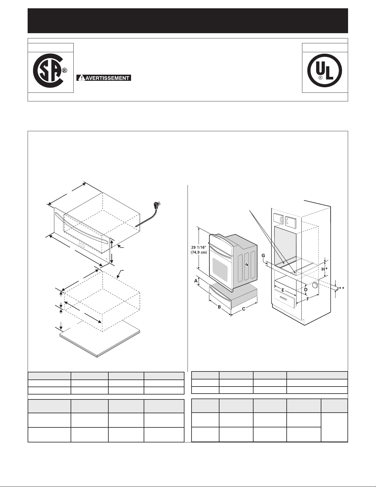
H*=11-7/8"(30.2cm)Min.estl'espace
requisentrelebasdel'ouverturedutiroirréchaudetlebas
del'ouverturedufour.Cettedimensionestcritiqueetdoit
êtrerespectée.
J**=3"(7.6cm)Max.Laboîtedejonctionélectriquepourle
fourencastrédoitêtresituéeenbasdudécoupagepourle
tiroirchauant.
UN INSTALLATEUR QUALIFIÉ DOIT EFFECTUER
L’INSTALLATION ET LE SERVICE.
IMPORTANT: CONSERVEZ CES INSTRUCTIONS POUR LES INSPECTEURS LOCAUX.
LISEZ CES INSTRUCTIONS ET CONSERVEZ-LES POUR RÉFÉRENCES ULTÉRIEURES.
POUR VOTRE SÉCURITÉ: N’entreposez et n’utilisez pas
d’essenceoud’autresproduitsinammablesàproximitédecetappareilou
de tout autre appareil.
Canada États-Unis
RENSEIGNEMENTS GÉNÉRAUX - Ce tiroir-
réchaud peut être utilisé de façon autonome
ou combiné à un four encastré superposé
IMPORTANT: Le tiroir-réchaud doit être installé sur une surface
de niveau, de gauche à droite et de l'arrière à l'avant. La
surface doit pouvoir supporter 100 lbs (45,4 Kg).
Dimensions du tiroir-réchaud
Installation pour appareil autonome
NOTE: Un câble de 60" (152 cm) est fourni avec le tiroir-
réchaud.
Modèles A. Hauteur B.Largeur C. Profondeur
27" 11¼" (28.6 cm) 27" (68.6 cm) 23 3/8" (59.4 cm)
30" 11¼" (28.6 cm) 30" (76.2 cm) 23 3/8" (59.4 cm)
Modèles
D. Hauteur du
découpage
E.Largeurdu
découpage
E. Profondeur
dudécoupage
27"
Min
.
9 7/8" (25.1 cm)
25½" (64.8 cm)
23 5/8" (60cm)
Max. 10¼" (26 cm)
25¾" (65.4 cm)
24" (61 cm)
30" Min. 9 7/8" (25.1 cm)
28½" (72.4 cm)
23 5/8" (60cm)
Max. 10¼" (26 cm)
28¾" (73 cm)
24" (61 cm)
Modèles A. Hauteur B.Largeur C. Profondeur
27" Models
11¼" (28.6 cm) 27" (68.6 cm)
23 3/8" (59.4 cm)
30" Models
11¼" (28.6 cm) 30" (76.2 cm)
23 3/8" (59.4 cm)
Modèles
D. Hauteur du
découpage
E.
Largeurdu
découpage
E.
Profondeur
dudécoupage
G.
Hauteur
27" Min
.
9 7/8" (25.1 cm) 25½" (64.8 cm) 23 5/8" (60cm) 2" (5.1 cm)
Dépend
de la
dimension
critique H
Max.
10¼" (26 cm) 25¾" (65.4 cm) 24" (61 cm)
30" Min.
9 7/8" (25.1 cm) 28½" (72.4 cm) 23 5/8" (60cm)
Max.
10¼" (26 cm) 28¾" (73 cm) 24" (61 cm)
10
INSTRUCTIONS D’INSTALLATION POUR LE TIROIR-RÉCHAUD
Notesimportantesàl’installateur
1. Liseztouteslesinstructionsd’installationavantdeprocéder
àl’installationdecetappareil.
2.Retireztoutlematérield’emballagedel’appareilavant
debrancherl’alimentationélectrique.
3.Observez tous les règlements et codes locaux
applicables.
4.Assurez-vousdelaissercesinstructionsàl’utilisateur.
Noteimportanteàl’utilisateur
Conservezcesinstructionspourréférencesultérieures.
INSTRUCTIONS DE SÉCURITÉ
IMPORTANTES
• Assurez-vous que votre appareil est installé et
raccordéàuneprisemuralede120voltsmiseàla
terre.
• Cetappareildoitêtremisàlaterreconformément
au code d’électricité national ANSI/NFPA No. 70,
dernièreédition,auxÉtats-Unis,ouàl'ACNORC22.1,
partie 1 au Canada, et aux codes et règlements
locaux.
Outils nécessaires
TournevisPhillips
Crayon
Règleourubanàmesureretéquerre
Scieàmainousciesauteuse
Niveauàbulle
Installation d’un tiroir-réchaud
1. Localisezlessupportsanti-basculetelqu'indiquéàlag.
1.
2.Glissezletiroirdansl'ouverturedudécoupagejusqu'àce
quesoncadreavantsoittoutcontrel'armoire.Veillezà
nepascoincerlecordonélectrique.
3.Retirezletiroirtelqu'expliquédanslemanueld'utilisation
etd'entretienetxezlechâssisdutiroiràl'armoireàl'aide
des3visplaquéesaunickelfournies.Neserrezpasles
visoutremesure(voirg.2)
4.Lecordond’alimentationdel’appareilde60"(152cm)
peutàprésentêtrebranché à laprisemuralede120
volts.
5.Procédez maintenant au montage du four encastré
superposé au tiroir-réchaud (s’il y a lieu). Suivez les
instructionsd’installationfourniesaveclefourencastré.
Assurez-vousd’utiliserlescrochetsanti-basculefournis
aveclefour.
c
/
c
25
5
/
16
"
(64.3cm)
24"(64.3cm)Max.
23
5
/
8
"(60cm)Min.
c
/
c
12
21
/
32
"
(32.15cm)
Figure1
Figure2
Utilisez les vis
fournies pour xer
le châssis du tiroir à
l'armoire.
11
INSTRUCTIONS D’INSTALLATION POUR LE TIROIR-RÉCHAUD
Emplacement des numéros de modèle et de
série
Laplaquesignalétiqueestsituéetelquemontréplus
bas.
Lorsd’unecommandedepiècesoupourtoutedemande
derenseignementsausujetdevotretiroirréchaud,
assurez-vousdetoujoursinclurelesnumérosdemodèle
etdesérieinscritssurlaplaquesignalétiquedevotre
appareil.
Emplacement de la
plaquesignalétique
Installation combinée
tiroir-réchaud / table de cuisson
Vouspouvezinstallerletiroir-réchaudencombinaison
avecunetabledecuissonélectriqueougaz,enrespectant
lescontraintesimposéesparlefeuilletd'installationde
cettetableafind'évitercertainesinterférencesavec
l'installationélectriqueougaz.
A
Découpage
delatable
decuisson
Découpage
dutiroirréchaud
Connexionélectrique
Circuit de dérivation de 120 volt, 60 Hertz, avec mise
à la terre appropriée, protégé par un disjoncteur de
15 ampères ou un fusible temporisé. N'utilisez pas de
rallongeélectriquepourbrancherlaplaquedecuisson.
IMPORTANTVeuillezlireattentivement.
Pourvotrepropresécurité,cetappareildoitêtre
correctementmisàlaterre.
Anderéduireauminimumlesrisquesdechocs
électriques,lecordond'alimentationdecetappareilest
munid'unechedecontacttripolaire(miseàlaterre)
enchabledansuneprisedecourantmuraletripolaire
standardavecmiseàlaterre.
Ilestconseillédefairevérierlaprisedecourant
muraleetlecircuitparunélectricienqualié,ande
s'assurerquelaprisedecourantestcorrectementmise
àlaterre.
Danslecasoùiln'yaqu'uneprisedecourantmurale
bipolairestandard,ilincombeauclientdelaremplacer
paruneprisedecourantmuraletripolairecorrectement
miseàlaterre.
Il est strictement interdit de couper ou d'enlever
latroisièmetige(miseàlaterre)ducordon
d'alimentation.
Débranchezlecordond'alimentation
électriquedelaprisedecourantmuraleavantde
répareroudenettoyerlaplaquedecuisson.
Méthode préférée
Assurez-vousque
l'appareilestbienmis
àlaterreavantde
l'utiliser
NE PAS, sous
aucune circonstance,
couper, enlever ou
outrepasser la tige
de mise à la terre.

12
NOTES