Loading ...
Loading ...
3
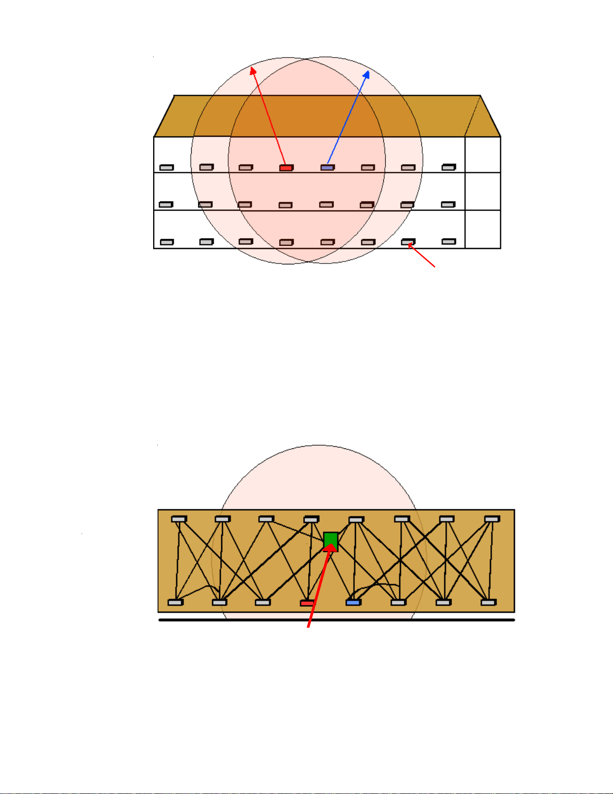
The diagram above shows the nominal transmission radius of the Router Transceivers of the DT01A devices installed in the
PTAC/PTHP units in a 3- story Hotel. They form a communication mesh much like a web. When a communication signal
needs to get from the most remote Guestroom PTAC unit to the Amana
®
Brand AX or vice versa, the signal is routed from
unit to unit to make the communication path. The signals can normally penetrate two floors up or down and depending upon
the interior construction materials used in your facility, through up to 6 drywall walls and up to 3 CMU or brick walls
horizontally. The red PTAC has neighboring units that it communicates to directly, as does the blue PTAC. Some of those
neighboring units are the same for both and some are not.
The diagram below shows the building viewed from above. The transmission radius of the red PTAC also captures a horizontal
group of neighbors as well. The overall transmission pattern is spherical except for behind the PTAC, or in this example,
everything below the red line. The reason is that the metal housing of the PTAC itself blocks the signal of the DT01A RF router
/ transceiver.
The mesh structure may actually look like this if you could see the pathways of the radio communications on a particular
floor. So when you power the Amana
®
Brand AX, it joins the Mesh as the Mesh Coordinator and will have many paths to route
communications to the PTAC’s located in the farthest corners of your building.
Front View
Top View
Amana® AX Location
Floor 3
Floor 2
Floor 1
PTAC
Amana
®
Brand AX Location
Loading ...
Loading ...
Loading ...