Loading ...
Loading ...
Loading ...
10 English
4. Use saber or keyhole saw to cut the circular vent opening. Repeat
steps 1-3 for the underside of the top of the cabinet.
Cabinet cutouts
*From wall, not cabinet frame
*5”
(12.8 cm)
Centerline
Drill Electrical Opening
1. Using a 1¼" (3 cm) drill bit, drill the hole in the dot marked previously
at the electrical strain relief.
OPTIONAL: Using a ⅛" (3 mm) drill bit, drill pilot holes for the dots
marked previously at each mounting tab at an approximate 45° angle in
an upward direction.
Prepare Range Hood Vents
A
B
C
D
E
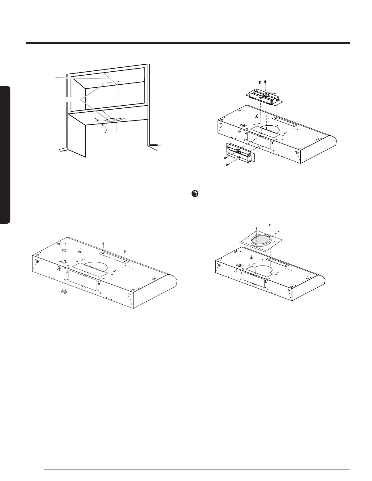
Install Strain Relief
1. Install a UL listed/CSA approved ½" (13 mm) strain relief (A).
For non-vented (Recirculating) Installations
• Remove the (2) T10 Torx® screws and remove the top, front rect-
angular vent cover (E). Go to "Electrical Connection" step.
For 3¼" x 10" (8.3 x 25.4 cm) Rectangular Vent Installations
• For top vent installations, remove the top rectangular vent knock-
out (C).
OR
• For wall vent installations, remove the rear rectangular vent knock-
out (B).
For 7" (17.8 cm) Round Vent Installations
• Remove both top knockouts (C and D).
Attach Vent Damper or Transition
3¼" x 10" (8.3 x 25.4 cm) Rectangular Vent Damper
1. Using (2) short Phillips head screws, install the 3¼" x 10" (8.3 x 25.4
cm) rectangular damper over the top or rear vent knockout removed
in previous step.
NOTE
If the wall cap used has a damper and it interferes with the rectangular
damper, remove the rectangular damper ap.
7" (17.8 cm) Round Vent Mounting Plate
A
B
1. Using (2) short Phillips head screws, install the 7" (17.8 cm) round
vent mounting plate (A) over the vent knockouts removed in previ-
ous step. Position the wide ange (B) to the front.
■ If installing the optional round damper, position it over the round vent
mounting plate.
Installation Instructions
Installation Instructions
Loading ...
Loading ...
Loading ...