Loading ...
Loading ...
Loading ...
INSTALLATION INSTRUCTIONS
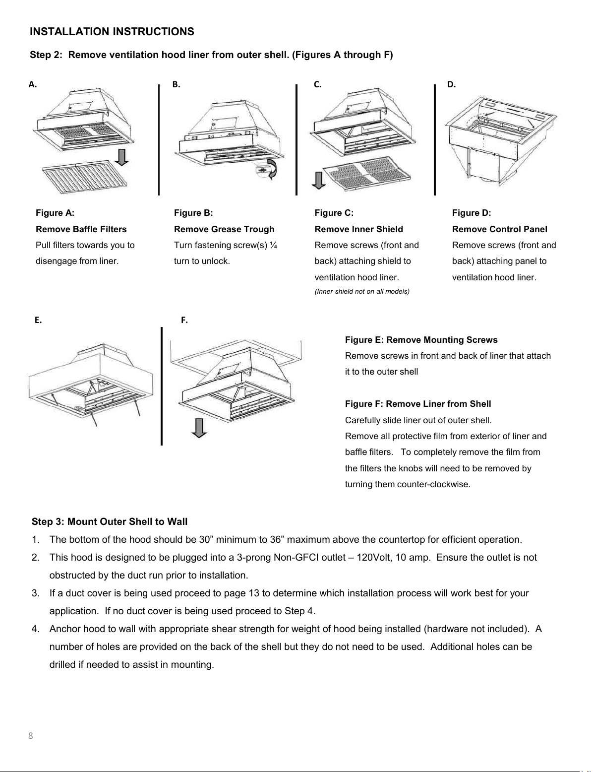
Figure E: Remove Mounting Screws
Remove screws in front and back of liner that attach
it to the outer shell
Figure F: Remove Liner from Shell
Carefully slide liner out of outer shell.
Remove all protective film from exterior of liner and
baffle filters. To completely remove the film from
the filters the knobs will need to be removed by
turning them counter-clockwise.
E. F.
Step 3: Mount Outer Shell to Wall
1. The bottom of the hood should be 30” minimum to 36” maximum above the countertop for efficient operation.
2. This hood is designed to be plugged into a 3-prong Non-GFCI outlet – 120Volt, 10 amp. Ensure the outlet is not
obstructed by the duct run prior to installation.
3. If a duct cover is being used proceed to page 13 to determine which installation process will work best for your
application. If no duct cover is being used proceed to Step 4.
4. Anchor hood to wall with appropriate shear strength for weight of hood being installed (hardware not included). A
number of holes are provided on the back of the shell but they do not need to be used. Additional holes can be
drilled if needed to assist in mounting.
Step 2: Remove ventilation hood liner from outer shell. (Figures A through F)
Figure A:
Remove Baffle Filters
Pull filters towards you to
disengage from liner.
Figure B:
Remove Grease Trough
Turn fastening screw(s) ¼
turn to unlock.
Figure C:
Remove Inner Shield
Remove screws (front and
back) attaching shield to
ventilation hood liner.
(Inner shield not on all models)
Figure D:
Remove Control Panel
Remove screws (front and
back) attaching panel to
ventilation hood liner.
A. B. C. D.
8
Loading ...
Loading ...
Loading ...