Questions, problems, missing parts? Before returning to your retailer, call our customer
service department at 1-800-643-0067, 8 a.m. - 6 p.m., EST, Monday - Thursday, 8 a.m. - 5 p.m.,
EST, Friday.
1
Harbor Breeze® is a registered trademark
of LF, LLC. All Rights Reserved.
ATTACH YOUR RECEIPT HERE
Purchase Date _________________________
Español p. 19
EB16263
ITEM #0609448
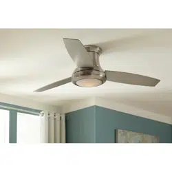
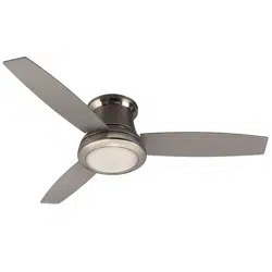
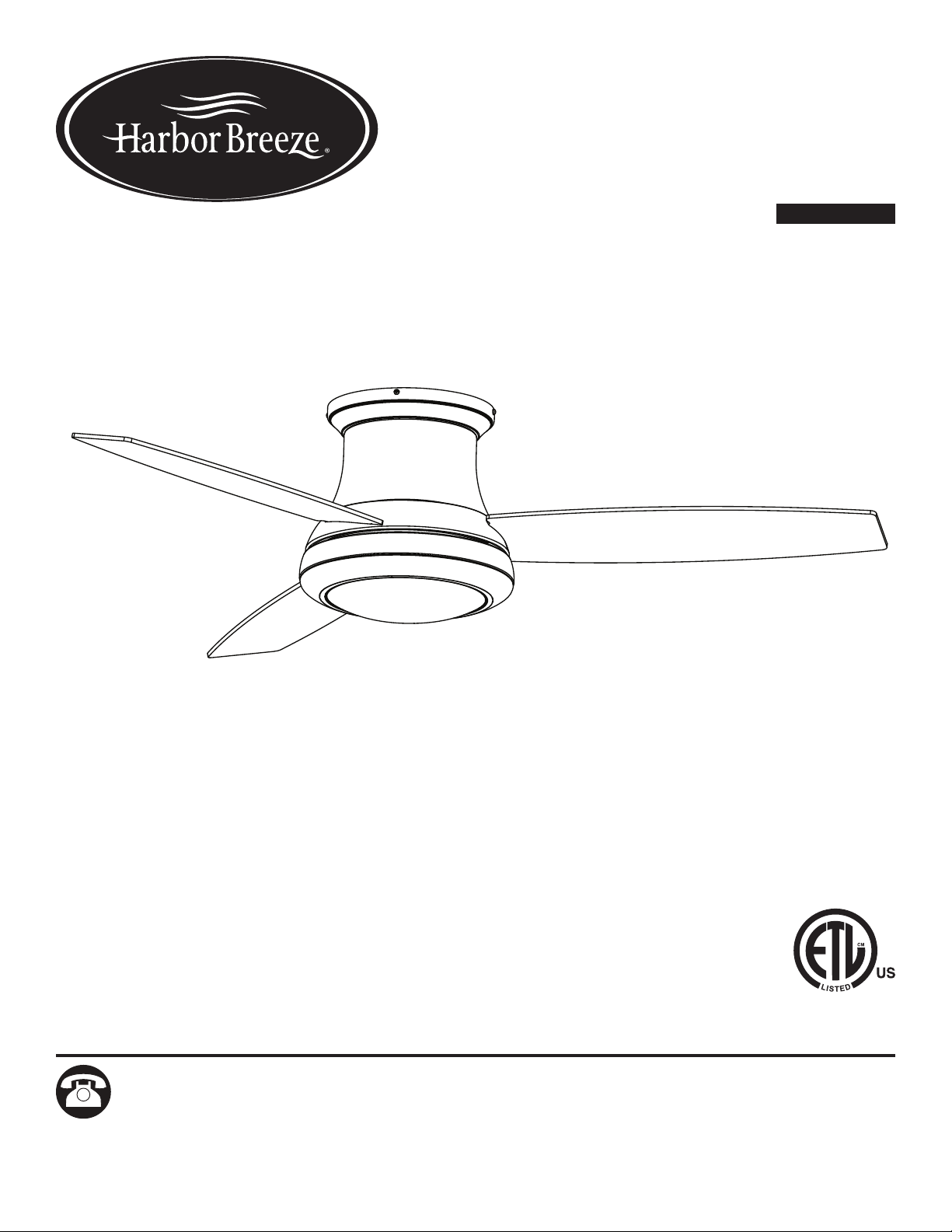
SAIL STREAM
CEILING FAN
MODEL #40048

2
TABLE OF CONTENTS
Package Contents .................................................................3
Hardware Contents ................................................................4
Safety Information .................................................................5
Preparation ......................................................................6
Initial Installation ..................................................................7
Wiring ..........................................................................9
Final Installation. . . . . . . . . . . . . . . . . . . . . . . . . . . . . . . . . . . . . . . . . . . . . . . . . . . . . . . . . . . . . . . . . . 10
Operating Instructions .............................................................14
Care and Maintenance ............................................................15
Troubleshooting ..................................................................15
Warranty .......................................................................17
Replacement Parts List ............................................................18
3
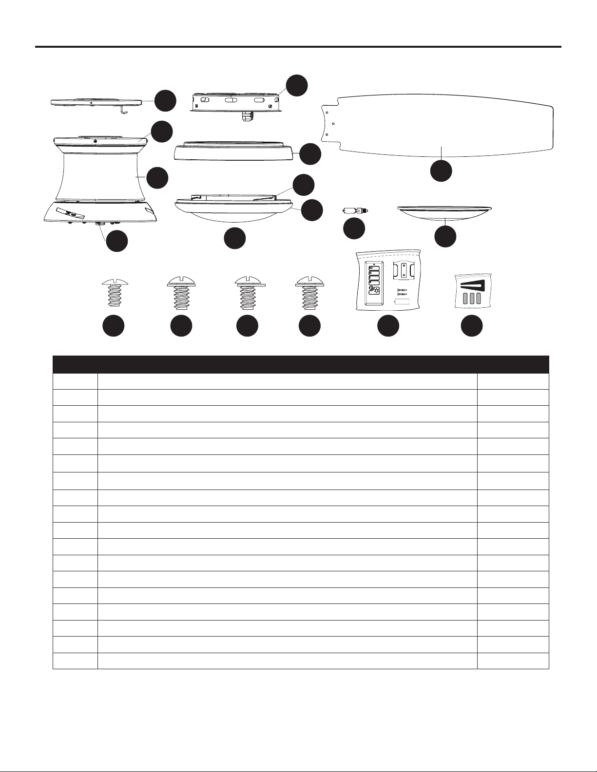
PACKAGE CONTENTS
PART DESCRIPTION QUANTITY
A Mounting Bracket 1
B Canopy (preassembled to Motor Assembly [C]) 1
C Motor Assembly 1
D Fitter Plate (preassembled to Motor Assembly [C]) 1
E Switch Housing 1
F Light Pan 1
G Locking Ring (preassembled to Bowl Housing [H]) 1
H Bowl Housing 1
I Glass Bowl (preassembled to Bowl Housing [H]) 1
J Blade 3
K Bulb 1
L Metal Bowl 1
M Mounting Bracket Scew (preassembled to Mounting Bracket [A]) 4
N Switch Housing Screw (preassembled to Light Pan [F]) 3
O Light Pan Screw (preassembled to Fitter Plate [D]) 4
P Locking Ring Screw (preassembled to Bowl Housing [H] 3
Q Remote Pack 1
R Blade Balancing Kit 1
A
B
D
C
E
G
F
H
I
J
L
K
M N O P Q R
4
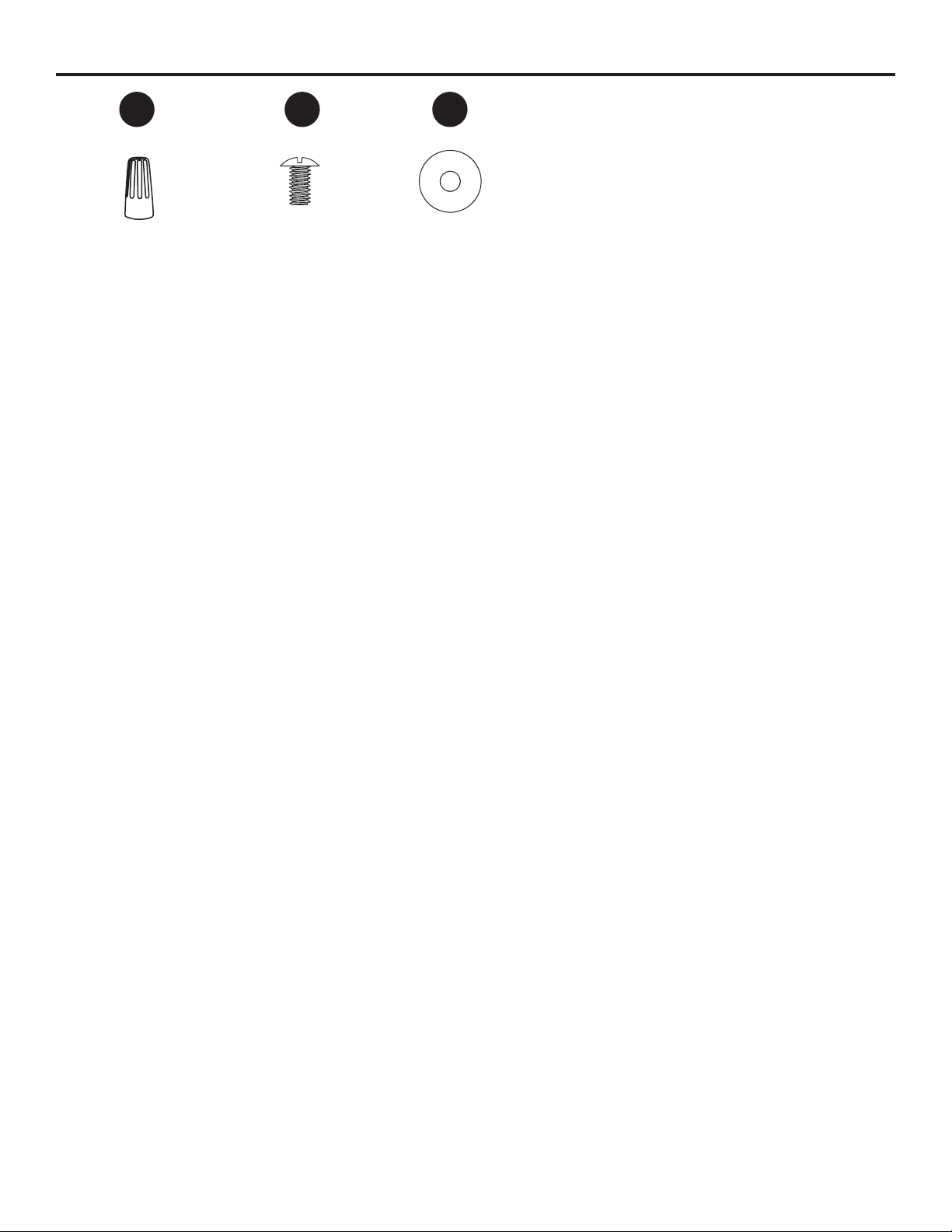
HARDWARE CONTENTS (shown actual size)
Wire Connector
Qty. 3
+ 1 extra
Blade Screw
Qty. 9
+ 1 extra
Blade Washer
Qty. 9
+ 1 extra
AA BB CC
5
SAFETY INFORMATION
Please read and understand this entire manual before attempting to assemble, operate or install the
product.
• Before you begin installing the fan, disconnect the power by removing fuses or turning off the circuit
breakers.
• Make sure all electrical connections comply with local codes, ordinances, the National Electrical
CodeandANSI/NFPA70-199.Hireaqualiedelectricianorconsultado-it-yourselfwiring
handbook if you are unfamiliar with installing electrical wiring.
• Make sure the installation site you choose allows a minimum clearance of 7 ft. from the blades to
theoorandatleast30in.fromtheendofthebladestoanyobstruction.
• The net weight of this fan is: 17.64 lbs.
DANGER: When using an existing outlet box, make sure the outlet box is securely attached to
the building structure and can support the full weight of the fan. Failure to do this can result in serious
injury or death. The stability of the outlet box is essential in minimizing wobble and noise in the fan
after installation is complete.
WARNING: To avoid personal injury, the use of gloves may be necessary while handling fan
parts with sharp edges.
WARNING: Using a full-range dimmer switch to control fan speed will cause a loud humming
noisefromthefan.Toreducetheriskofreorelectricshock,doNOTuseafull-rangedimmerswitch
to control the fan speed.
WARNING: Toreducetheriskofre,electricshockorpersonalinjury,mountthefantoan
outlet box marked “ACCEPTABLE FOR FAN SUPPORT” and use the mounting screws provided with
theoutletbox.Mostoutletboxescommonlyusedforthesupportoflightingxturesarenotacceptable
forfansupportandmayneedtobereplaced.Consultaqualiedelectricianifindoubt.Securethe
outlet box directly to the building structure. The outlet box and its support must be able to support the
moving weight of the fan (at least 35 lbs.).
WARNING: Toreducetheriskofre,electricalshockorpersonalinjury,wireconnectors
provided with this fan are designed to accept only one 12-gauge house wire and two lead wires from
the fan. If your house wire is larger than 12-gauge and there is more than one house wire to connect
to the two fan lead wires, consult an electrician for the proper size wire connectors to use.
WARNING: Toreducetheriskofre,electricshockorpersonalinjury,donotbendtheblade
arms when installing them, balancing the blades or cleaning the fan. Do not insert objects between
the rotating fan blades.
WARNING: To reduce the risk of personal injury, use only parts provided with this fan. The use
of parts OTHER than those provided with this fan will void the warranty.

6
SAFETY INFORMATION
CAUTION: Be sure the outlet box is properly grounded or that a ground (green or bare) wire is present.
CAUTION: Carefully check all screws, bolts and nuts on the fan motor assembly to ensure they are
secured.
CAUTION: This device complies with Part 15 of the FCC Rules. Operation is subject to the following
two conditions: (1) this device may not cause interference, and (2) this device must accept any
interference received, including intererence that may cause undesired operation of the device.
PREPARATION
Before beginning the assembly of this product, ensure that all parts are present. Compare all parts
with the package contents list and hardware contents list. If any part is missing or damaged, do not
attempt to assemble the product.
Estimated Assembly Time: 120 minutes
Tools Required for Assembly (not included): Electrical Tape, Phillips Screwdriver, Pliers, Safety
Glasses, Step Ladder, Wire Cutters and Wire Strippers
Helpful Tools (not included): AC Tester Light, Tape Measure and Wiring Handbook
7
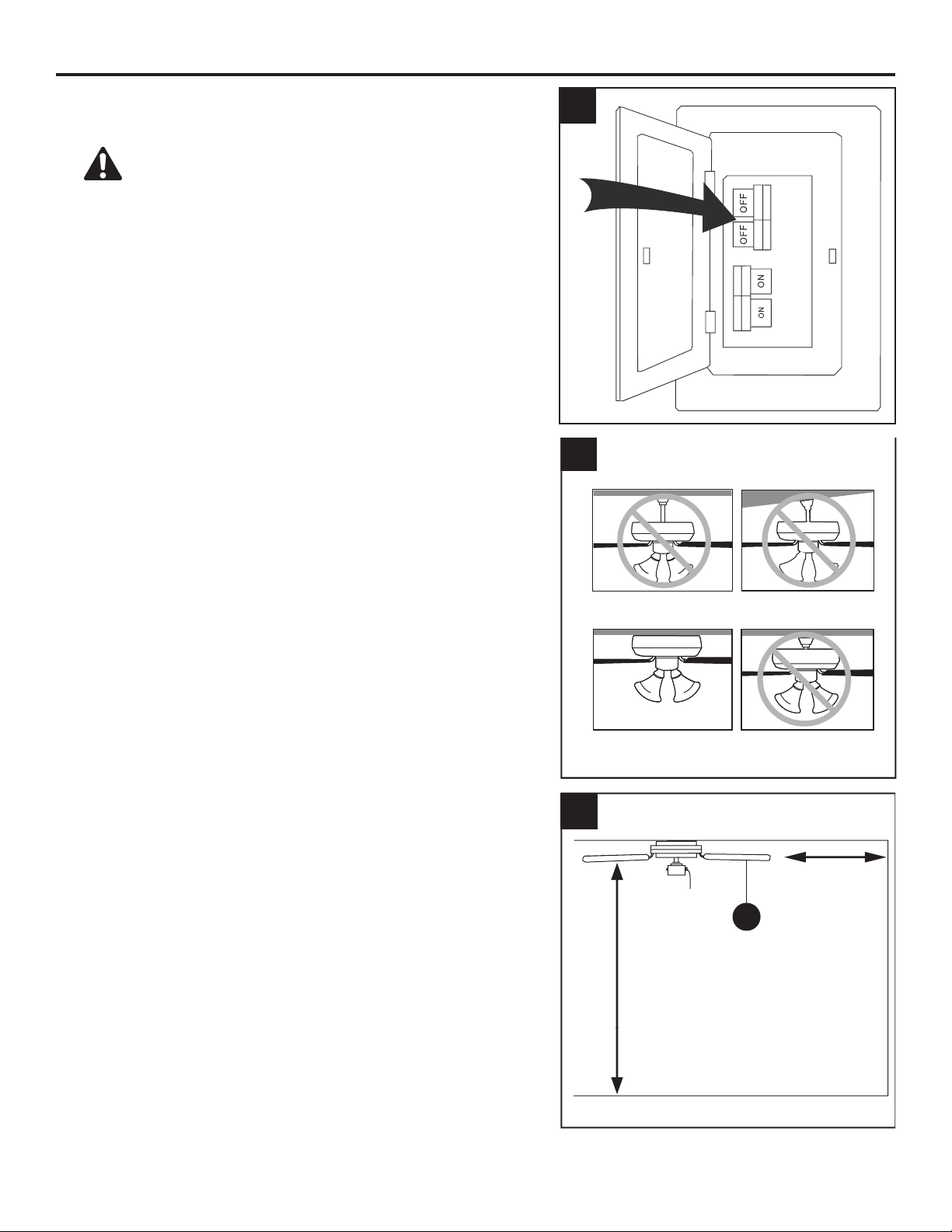
INITIAL INSTALLATION
1. Turn off the circuit breakers and the wall switch to the
fan supply line leads.
DANGER: Failure to disconnect the power
supply prior to installation may result in serious injury
or death.
2. This fan is intended for Flushmount Installation.
Standard Mounting, Angle Mounting, and Closemount
installations are not available.
3. Ensure the blades (J) will be at least 30 in. from any
obstructionsandwillbeatleast7ft.abovetheoor.
3
2
Standard Mounting
Flushmount Closemount
Angle Mounting
1
7 ft. Min
30 in. Min
J
8
INITIAL INSTALLATION
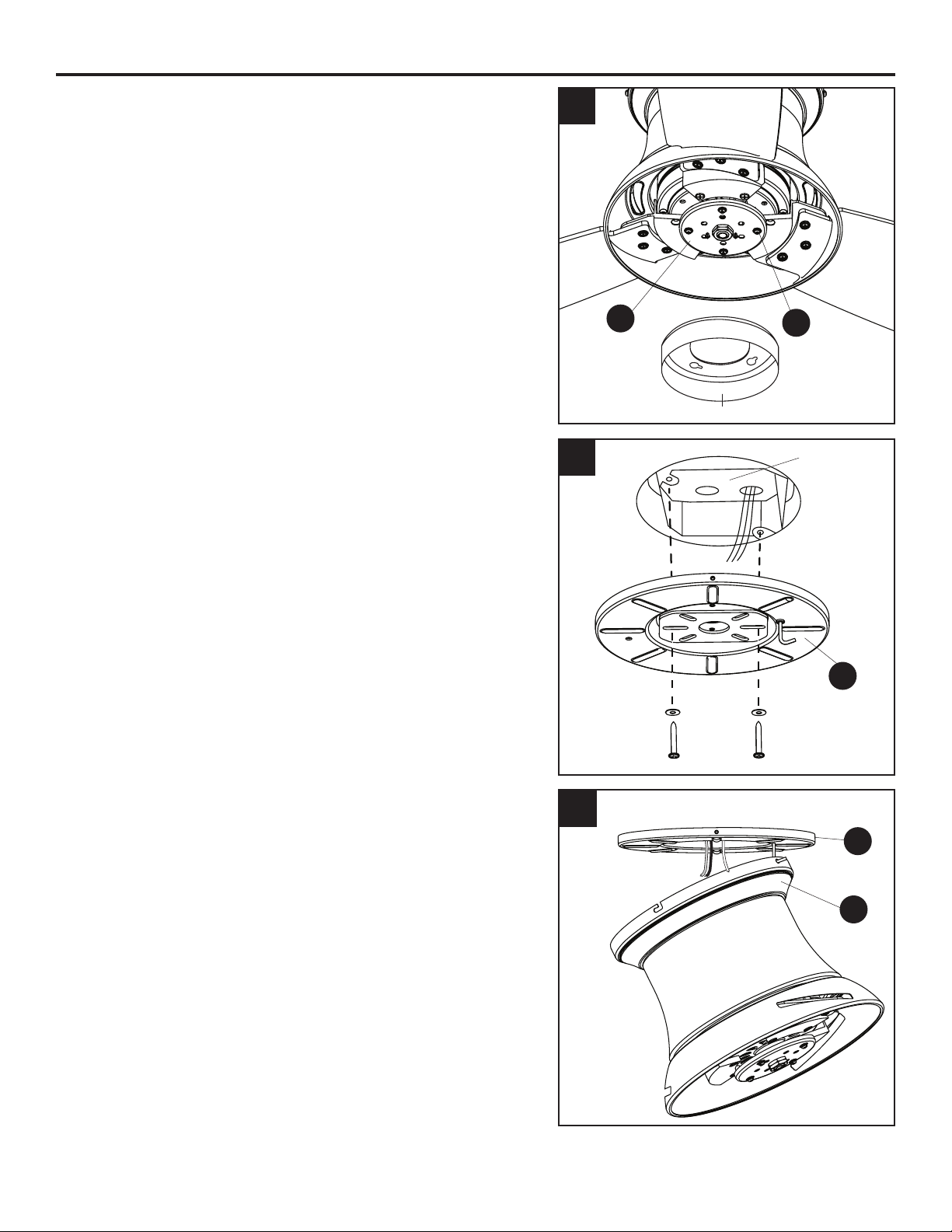
4. Loosen the four light pan screws (O) preassembled
tothetterplate(D).Then,turntheorangeshipping
block counterclockwise and remove. Discard the
shipping block.
5. Feed the supply wires from the outlet box through
the center hole in the mounting bracket (A). Then,
secure the mounting bracket (A) to the outlet box (not
included) using screws and washers provided with the
outlet box.
CAUTION: It is very important you use the proper
hardware when installing the mounting bracket (A) as it
will support the fan.
6. Raise the fan and place the canopy (B) on the hook
on the mounting bracket (A), temporarily leaving
hands free for the wiring process.
5
5
4
O
D
6
Outlet Box
B
A
A
Shipping Block
9
WIRING
WARNING:Toreducetheriskofre,electricalshockorpersonalinjury,wireconnectors
provided with this fan are designed to accept only one 12-gauge house wire and two lead wires
from the fan. If your house wire is larger than 12-gauge and/or there is more than one house wire to
connect to the two fan lead wires, consult an electrician for the proper size wire connectors to use.
CAUTION: Be sure the outlet box is properly grounded or that a ground (green or bare) wire is present.
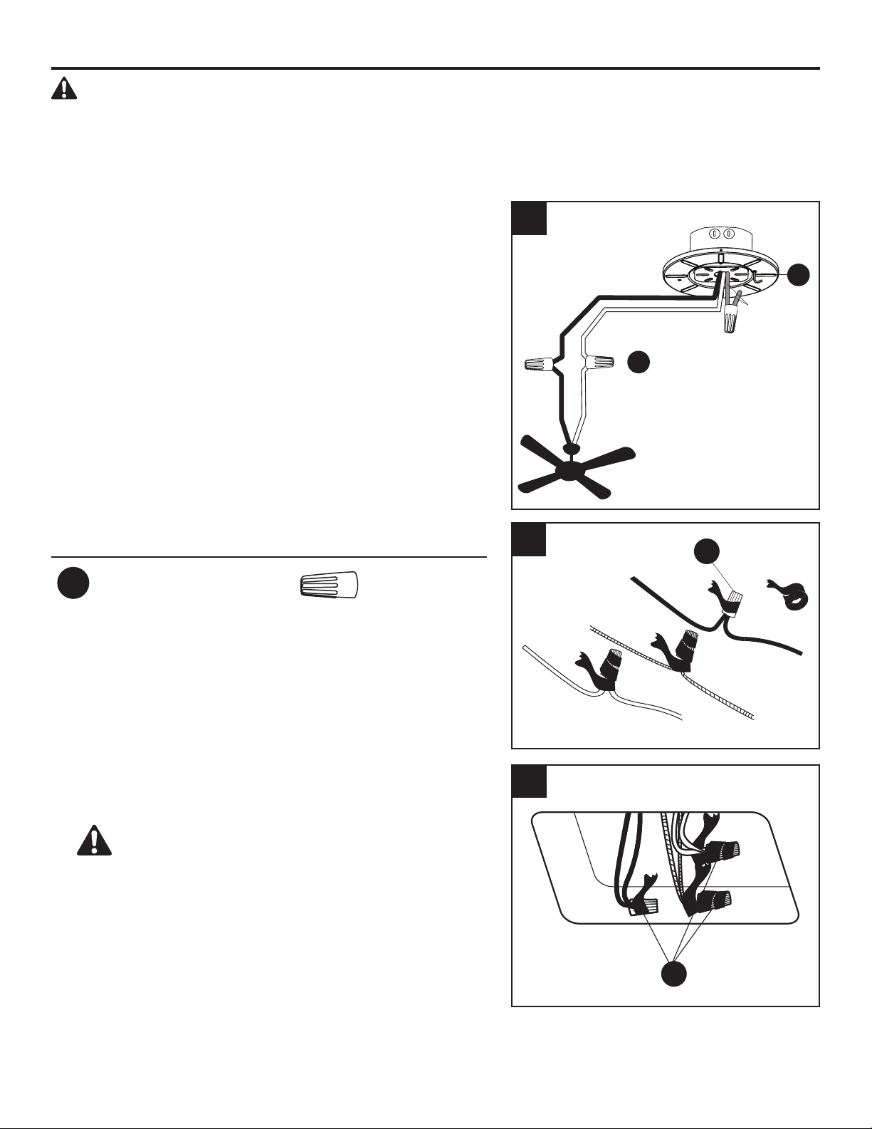
1. Connect supply and fan wires according to the
diagram and these steps:
•ConnecttheGreenwirefromthemountingbracket
(A) to the Bare/Green (ground) supply wire.
•ConnecttheWhitewirefromthefantotheWhite
(neutral) supply wire.
•ConnecttheBlackwirefromthefantotheBlack
(hot) supply wire.
Secure all wiring connections together with wire
connectors (AA).
Note: The Black wire is hot power for the fan. The
White wire is neautral for the fan and light kit. The
Green wire is the ground wire. If supply wires are
different colors than referred to above, a professional
electrician should determine the proper wiring.
Hardware Used
AA
Wire Connector x 3
White (neutral)
Black
Black (hot)
White
2. Wrap electrical tape (not included) around each
individual wire connector (AA) down to the wire.
3. Turn the spliced/taped wires upward and gently push
the wires and wire connectors (AA) into the outlet box.
WARNING: Ensure no wire strands are visible
after making connections. Place the Green and White
wire connections on the opposite side of the outlet
box from the Black.
1
3
AA
AA
2
A
AA
Bare/Green
(Ground)
10
FINAL INSTALLATION
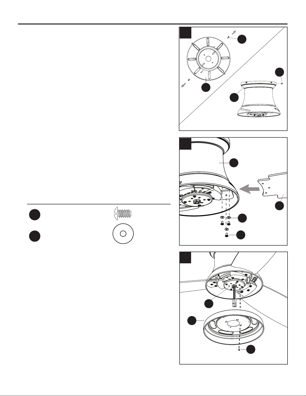
1. Loosen all four mounting bracket screws (M), then
completely remove two mounting bracket screws (M)
from opposite sides of the mounting bracket (A).
Slide the canopy (B) over the mounting bracket (A),
aligning the slotted holes in the canopy (B) with the
pre-loosened mounting bracket screws (M) in the
mounting bracket (A). Twist the canopy (B) clockwise
to lock. Then re-insert the mounting bracket screws (M)
and securely tighten all screws.
2. Insert blade (J) through slot in the side of the motor
assembly (C), ensuring the “THIS SIDE UP” label faces
the ceiling. Align the holes of one blade (J) with three
blade screw holes in underside of the motor assembly
(C). Secure blade (J) with three blade screws (BB) and
blade washers (CC).
Repeat for the remaining blades (J).
Hardware Used
BB
Blade Screw x 9
CC
Blade Washer x 9
3. Removeoneofthelightpanscrews(O)fromthetter
plate (D). Then, insert the wires from the center of the
tterplate(D)throughtheholeinthelightpan(F).Align
the light pan (F) over the previously loosened light pan
screws (O), then place the keyholes of the light pan (F)
clockwise. Secure the light pan (F) with the previously
removed light pan screw (O). Tighten all four light pan
screws (O).
1
2
J
M
A
B
BB
CC
M
3
D
F
O
C
11
FINAL INSTALLATION
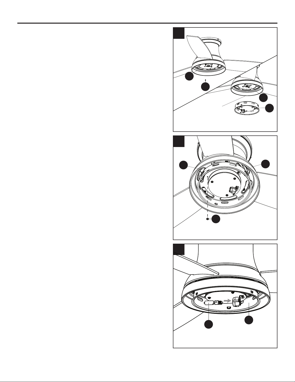
4. Note: If you wish to install the fan without the light
kit, proceed to Step 8.
To install the fan with the light kit, remove one of the
switch housing screws (N) from the light pan (F), and
loosen (do not remove) the other two screws.
Connectthe2-pinconnectorfromthecenterofthetter
plate (D) to the 2-pin connector from the switch housing
(E).
5. Align the switch housing (E) over the loosened switch
housing screws (N) preassembled on the switch
housing (E), then place the keyholes of the switch
housing (E) onto the switch housing screws (N) and
rotate the switch housing (E) clockwise. Secure the
switch housing (E) with the previously removed switch
housing screw (N). Tighten all three switch housing
screws (N).
6. Important: Oils from your hands will shorten the life of
a halogen bulb. It is important to use gloves or a piece
of cloth to handle the bulb during installation.
Install the bulb (K) into the socket on the switch housing
(E).
WARNING: Make sure you allow the bulb (K) and
switch housing (E) to cool before you replace the bulb.
6
4
E
F
N
5
D
F
E
N
2-pin connector
K
E
12
FINAL INSTALLATION
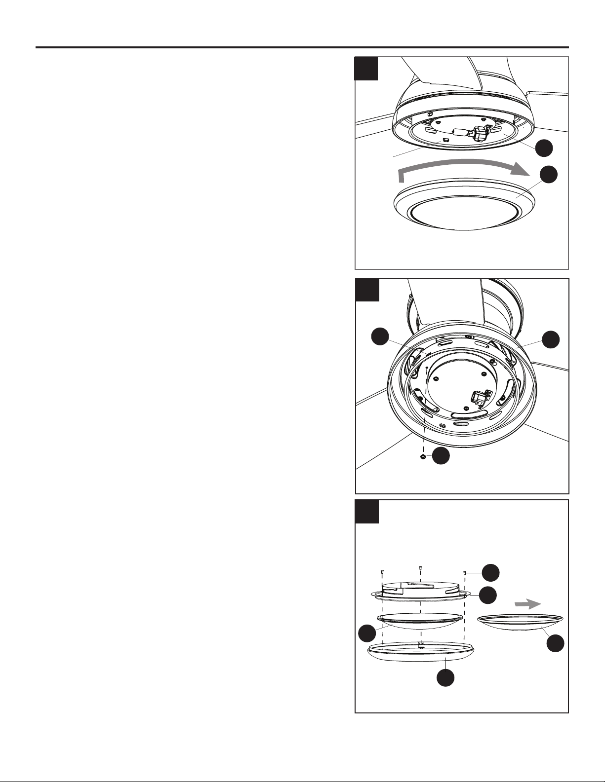
7. Align the notches in the switch housing (E) with the
grooves in the locking ring (G) preassembled to bowl
housing (H). Then, twist the locking ring (G) tightly in a
clockwise direction until it is secure.
Turn on the circuit breakers and the wall switch to the
fan supply lead lines.
Skip to step 11.
8. To install the fan without the light kit, remove one
of the switch housing screws (N) from the light pan (F),
and loosen (do not remove) the other two. Align the
switch housing (E) over the loosened switch housing
screws (N) preassembled on the switch housing (E),
then place the keyholes of the switch housing (E) onto
the switch housing screws (N) and rotate the switch
housing (E) clockwise. Secure the switch housing (E)
with the previously removed switch housing screw (N).
Tighten all three switch housing screws (N).
WARNING: Do not cut, remove or connect the 2-pin
connectors if installing without the light kit.
9. Remove the locking ring (G) from the bowl housing
(H) by removing the three locking ring screws (P) from
the locking ring (G). Then remove the preassembled
glass bowl (I) and replace with the metal bowl (L).
Reinstall the locking ring screws (P) to secure the bowl
assembly.
CAUTION: Metal bowl (L) is only suitable for
installations without the light kit.
E
G
F
E
7
8
9
Notch
N
G
I
P
L
H
13
FINAL INSTALLATION
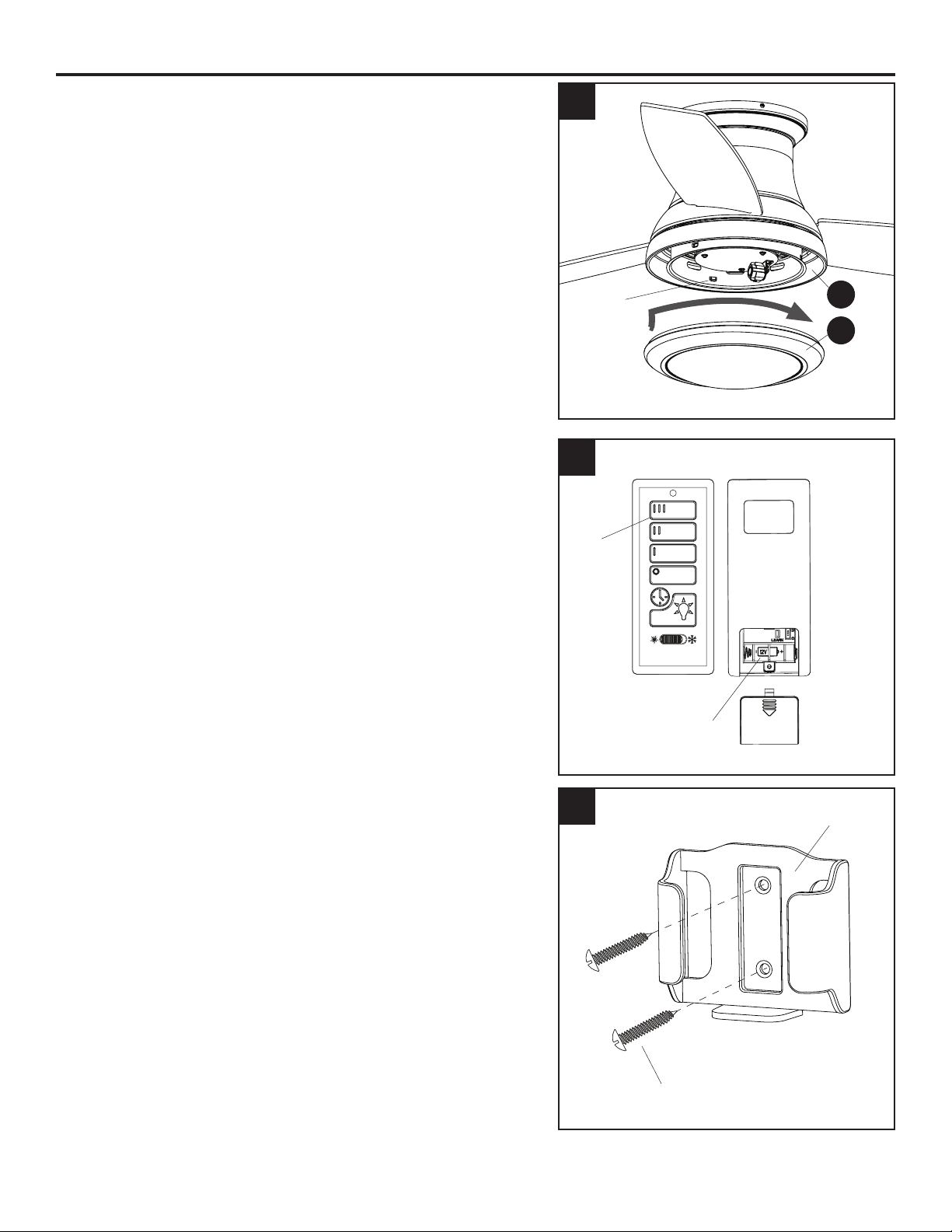
10. Align the notches in the switch hosing (E) with the
grooves in the locking ring (G) preassembled to bowl
housing (H). Then, twist the locking ring (G) tightly in
a clockwise direction until it is secure.
Turn on the citcuit breakers and the wall switch to the
fan supply lead lines.
11. Remove the battery cover from the back of the
remote found in remote pack (Q). Insert the battery
from remote pack (Q) into the remote; ensure polarity
of battery matches the polarity indicated in the
battery compartment -- positive (+) to positive (+) and
negative (-) to negative (-). Replace the battery cover
and press the high fan speed button on the remote to
ensure the remote turns on the fan.
Note: If remote does not turn on fan, see
TROUBLESHOOTING (page 16).
12. If desired, the wall bracket in remote pack (Q) can
be installed to a wall using the provided mounting
screws. Store the remote on the wall bracket when
not in use.
10
12
E
G
11
Notch
Front Back
Battery
Compartment
Battery Cover
High
Fan
Speed
Wall Bracket
Mounting Screw
14
OPERATING INSTRUCTIONS
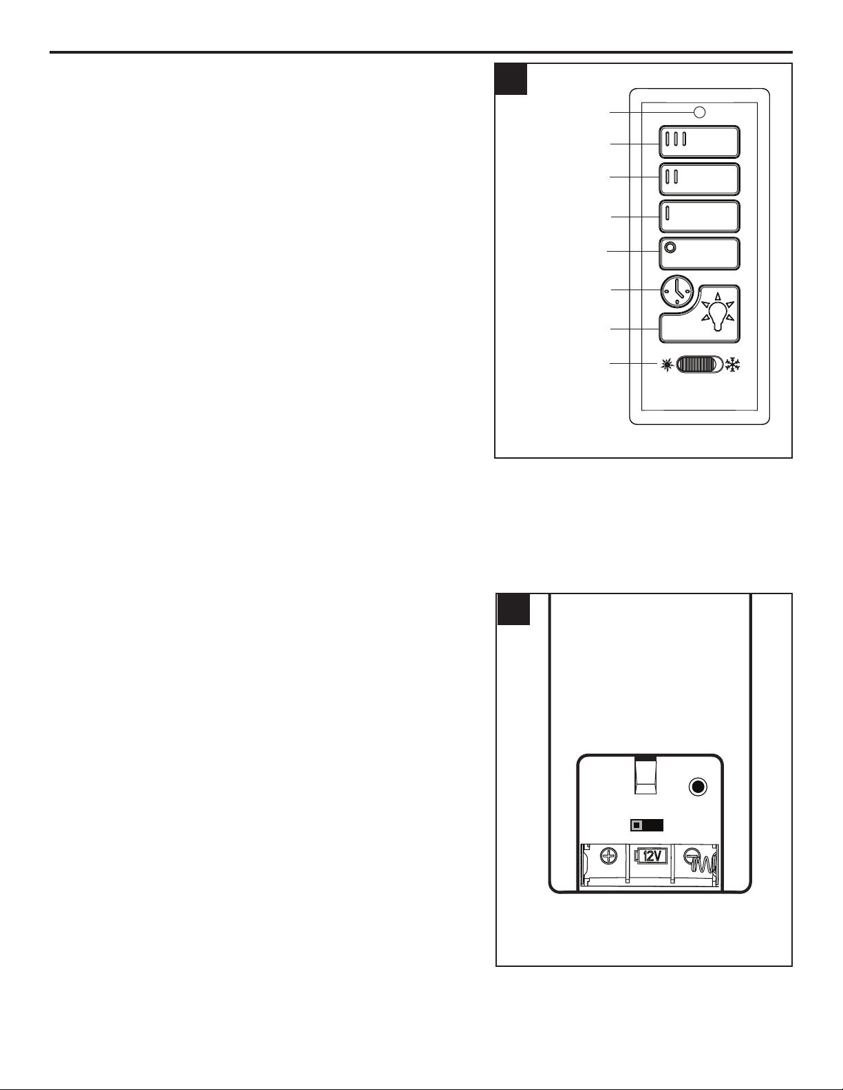
1. To operate the fan using the remote from remote pack
(Q), press and release the following buttons:
III - High speed
II - Medium speed
I - Low speed
Fan Off - Turns power to fan off.
Light Delay - Tap the light delay button, which will
turn off the light after one minute. Tap the light control
button to exit light delay mode.
Light Control - Tap the light control button to turn the
light off and on. Press and hold light control button to
dim or brighten the lights.
Seasonal Slide Switch - In warmer weather, push the
seasonal slide switch left toward sun icon, which will
resultindownwardairowcreatingawindchilleffect.
In cooler weather, push the seasonal slide switch right
towardthesnowakeicon,whichwillresultinupward
airowthatcanhelpmovehotairofftheceiling.
Important: Wait for the fan to stop before moving
the seasonal slide switch. The seasonal slide switch
must be set either completely left or right in order
for the fan to function correctly. If the switch is set in
the middle position, the fan will not operate.
Low Battery Indicator-LEDIndicatorwillashfor
one minute as a reminder to replace the 12-volt battery.
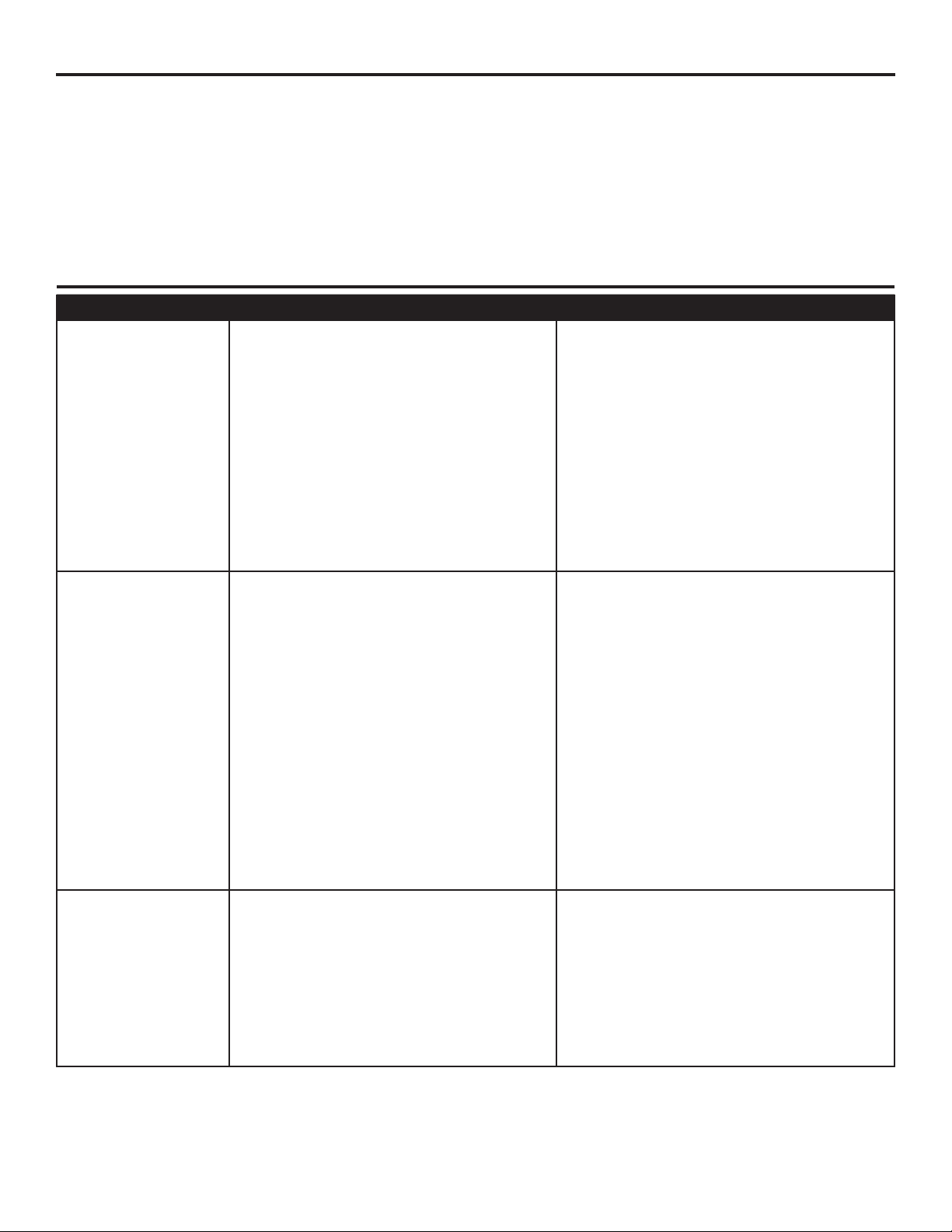
2. Remove battery door from back off the remote from
remote pack (Q) to access the following:
D/CFL Switch - set to “D” at the factory. The switch
should remain in the “D” position to ensure the halogen
bulb is dimmable.
LEARN - Syncs remote to receiver (see
troubleshooting for instructions).
1
2
High Speed
Led Indicator
Medium Speed
Low Speed
Fan Off
Light Delay
Light Control
Reverse Switch
Battery Compartment
(battery door removed)
D CFL
LEARN
15
CARE AND MAINTENANCE
At least twice each year, tighten all screws on the fan. Clean the motor housing with only a soft brush
orlint-freeclothtoavoidscratchingthenish.Cleanthebladeswithalint-freecloth.
Bulb Replacement: Use 75-watt max. halogen bulb or LED equivalent. CFL and incandescent bulbs
are not recommended for this item.
Battery Replacement for Remote: Use A23 12-volt battery.
Important: Shut off the main power supply before you begin any maintenance tasks. Do not use
water or a damp cloth to clean the ceiling fan.
TROUBLESHOOTING
PROBLEM POSSIBLE CAUSE CORRECTIVE ACTION
The fan does not
move.
1. The power is off or the fuse is
blown.
2. There is a faulty wire connection.
3. The plugs are not connected
properly.
4. The reverse switch is not
completely engaged.
1. Turn the power on or check the
fuse.
2. Turn the power off. Loosen the
canopy and check all connections.
3. Check that the connectors from
the light kit and fan are connected
properly.
4. Push the seasonal slide switch
completely to the left or right.
There is excessive
wobbling.
1. The blades and/or blade arms are
loose.
2. The blades are unbalanced.
3. The fan mounting is not secure.
1. Check and tighten all screws that
hold the fan blades to the blade
arms and the blade arms to the
motor.
2. Switch one blade with a blade from
the opposite side. Or balance the
fan using the blade balancing kit
(P).
3. Turn off the power. Loosen the
motor housing and verify the upper
mounting bracket is secure to the
electrical outlet box. The bracket
mustbeushwithoutmovement
against the outlet box.
The fan operates
correctly, but the
lights are not
working.
1. The bulbs are not installed
correctly.
2. The light kit wire plugs are not
connected properly.
3. There is a faulty wire connection.
1. Re-install the bulb(s).
2. Ensure the single-pin connectors in
the light kit are connected properly.
3. Turn the power off and check all
connections at the ceiling outlet
box.
16
TROUBLESHOOTING
PROBLEM POSSIBLE CAUSE CORRECTIVE ACTION
The fan is noisy.
1. The blades are loose.
2. There is a cracked blade.
3. The outlet box is not secure.
4. The mounting bracket is not
secure.
1. Check and tighten all screws that hold
the fan blades to the blade arms and the
motor.
2. Replace the cracked blade.
3. Ensure the ceiling outlet box is secured
to the building structure.
4. Ensure the mounting bracket is secured
to the outlet box and that the screws are
tight.
Remote control
does not work.
1. Power surge may have
cleared memory and remote
needs to be re-synced to the
reciever.
2. Battery in remote control
needs to be replaced.
3. Interface from another
remote.
1. After installation is complete, switch the
power off and back on again. Within
30 seconds, remove the battery from
remove pack (Q). Press and hold the
“LEARN” button, located in the battery
compartment, for 5 seconds. Fan
will turn on at low speed and light (if
installed)off.Thisconrmsthatthe
SMART SYNC is active.
2. Insert new 12V battery in battery
compartment of the remote control (see
page 13).
3. If there are several fans in close
proximity, turn power off to other fans
and re-sync the remote (see Corrective
Action 1 above).

17
LIFETIME LIMITED WARRANTY
The manufacturer warrants this fan to be free from defects in workmanship and materials present at
time of shipment from the factory for a lifetime from the date of purchase by the original purchaser.
The retailer also warrants that all other fan parts, excluding any glass or plastic blades, to be free
from defects in workmanship and material at the time of shipment from the factory for a period of one
year after the date of purchase by the original purchaser. The manufacturer agrees to correct such
defects without charge or at its option replace the ceiling fan with a comparable or superior model.
To obtain warranty service, present a copy of the receipt as proof of purchase. All costs of removing
and reinstalling the product are your responsibility. Any damage to any part such as by accident or
misuseorimproperinstallationorbyafxinganyaccessories,isnotcoveredbythiswarranty.The
manufacturer assumes no responsibility whatsoever for fan installation during the limited lifetime
warranty. Any service performed by an unauthorized person will render the warranty invalid.
Duetovaryingclimateconditions,thiswarrantydoesnotcoveranychangesinbrassnish,including
rusting,pitting,corroding,tarnishingorpeeling.Brassnishesofthistypegivetheirlongestusefullife
when protected from varying weather conditions. Any glass provided with this fan is not covered by
the warranty.
Anyreplacementofdefectivepartsfromtheceilingfanmustbereportedwithintherstyearfromthe
date of purchase. For the balance of the warranty, call our customer service department for return
authorization and shipping instructions so that we may repair or replace the ceiling fan. Any fan or
parts returned improperly is the sole responsibility of the purchaser. There is no other expressed
warranty. The manufacturer disclaims any and all warranties. The duration of any implied warranty
whichcannotbedisclaimedislimitedtothetimeperiodasspeciedintheexpressedwarranty.The
manufacturer shall not be liable for incidental, consequential, or special damages arising out of or
in connection with product use or performance except as may otherwise be accorded by law. This
warrantygivesspeciclegalrights,andyoumayalsohaveotherrightswhichvaryfromstatetostate.
This warranty supersedes all prior warranties.
Note: A small amount of “wobble” is normal and should not be considered a defect.
18
Printed in China
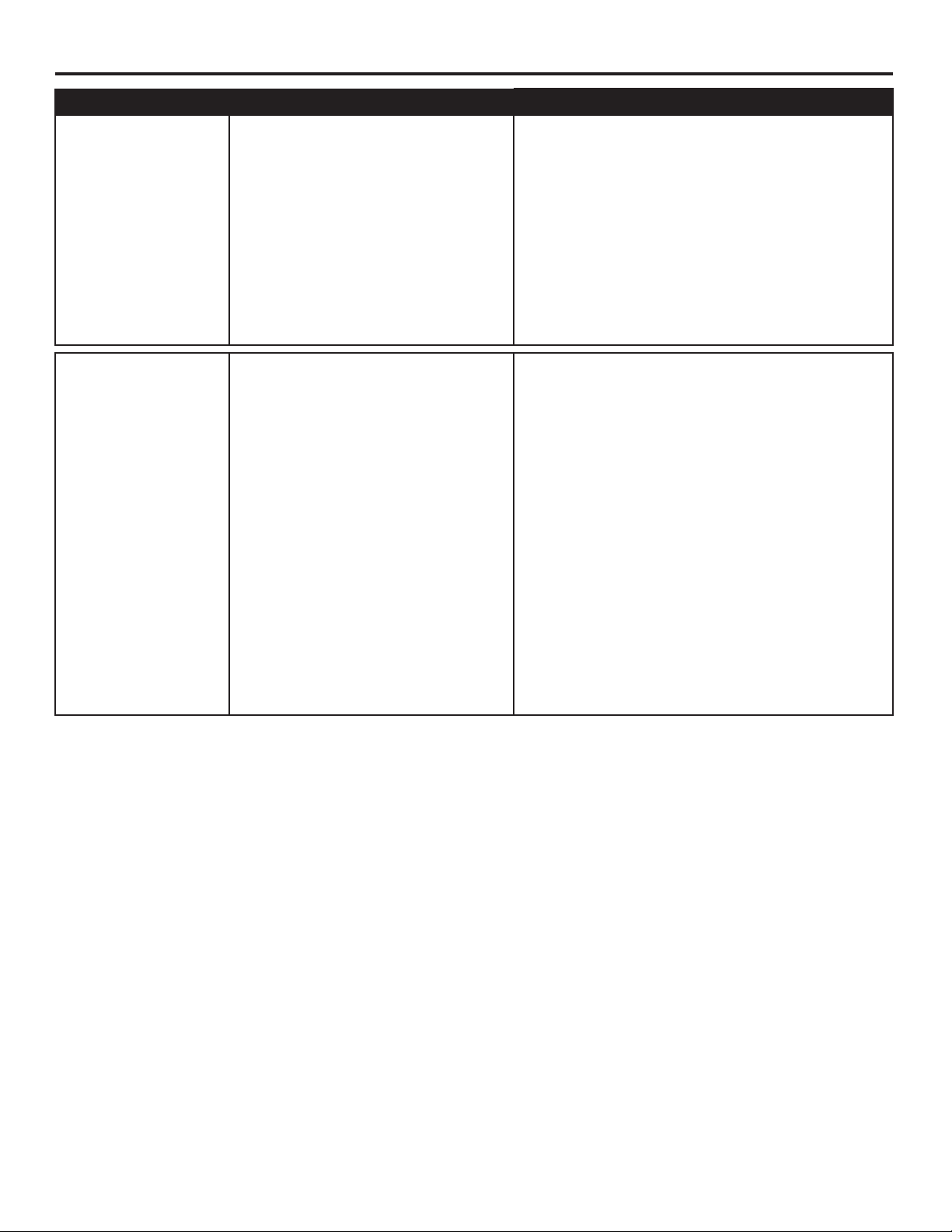
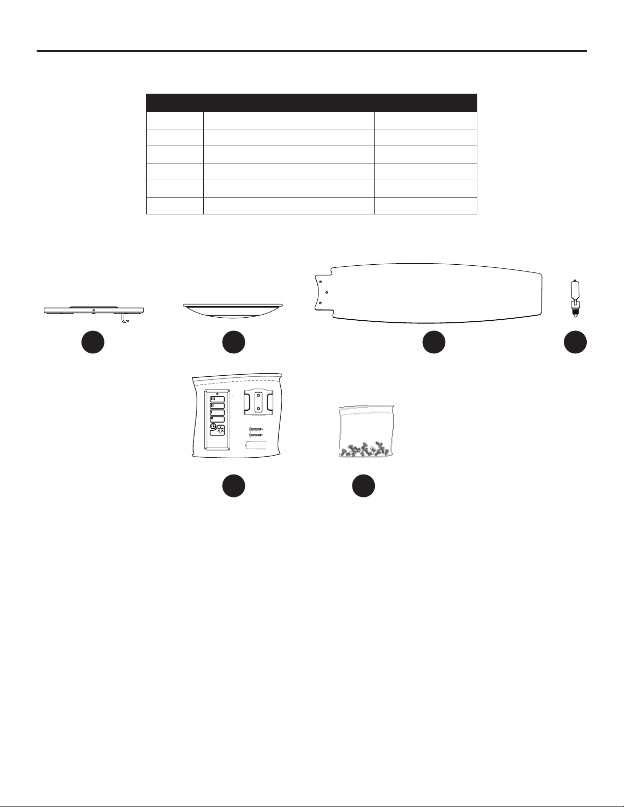
REPLACEMENT PARTS LIST
For replacement parts, call the customer service department at 1-800-643-0067, 8 a.m. - 6 p.m., EST,
Monday - Thursday, 8 a.m. - 5 p.m., EST, Friday.
PART DESCRIPTION PART#
A Mounting Bracket 0609448-A
I Glass Bowl 0609448-I
J Blade 0609448-J
K Bulb 0609448-K
Q Remote Pack 0609448-Q
HW Hardware Kit 0609448-HW
9113 ·103116
A
Q
KI
J
HW