Loading ...
Loading ...
Loading ...
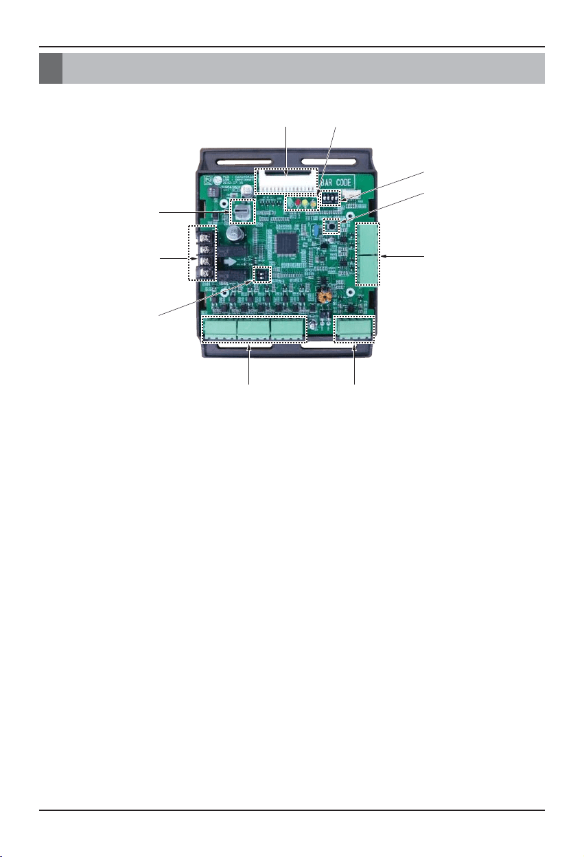
Name of each Part
6 Variable Water Flow Controller Kit
ڹ
ں
ڻ
ڼڽ
ڿ
ھ
ۀ
ڸہ
Name of each Part
① Main connector : Power input and communication connector with Outside Unit
② SW104 : Rotary Switch for setting capacity control step
③ Digital Output : Operating & Error status Relay output (DDC output AC 1A at 250V source)
④ SW102 : Switch for setting internal function
⑤ Digital Input : Dry contact input
⑥ Analog Input : DC 0~10V Analog signal input
⑦ Analog Output : DC 0~10V Analog signal output
⑧ SW103 : Reset Switch
⑨ SW101 : DIP Switch for setting operating function
⑩ LED : Indicate VWFC*(board) status
- LED1C(Green) : communication status (receive)
- LED2C(Red) : communication status (transfer)
- LED3C(Yellow) : Communication error status
- LED4C(Orange) : Power status
* Variable Water Flow Control Kit
Loading ...
Loading ...
Loading ...