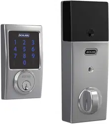
User manual Smart Deadbolt
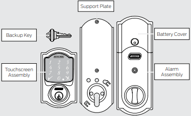
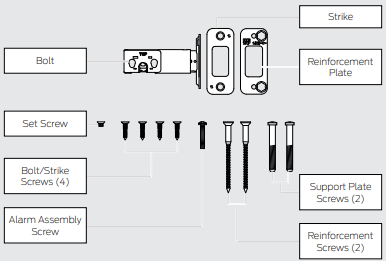
Package Contents
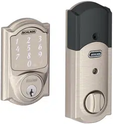
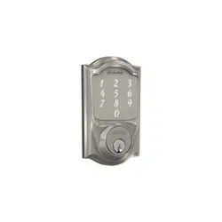
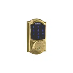
Camelot Style shown throughout guide.
Steps at a Glance
1 Download the app.
Download the Schlage Sense app from the App Store. Just search for “Schlage Sense” to find the app.

Apple HomeKit™ technology provides an easy, secure way to control your home’s lights, doors, thermostats, and more from your iPhone, iPad, or iPod touch.
HomeKit requires an iPhone, iPad, or iPod touch with iOS 8.4 or later.
2 Watch the installation video.
You can access installation videos in the app! The videos will give you a good overview of the installation process.
Alternatively, please visit answers.schlage.com and then click on Schlage Sense.
3 Check current door/frame alignment.
Because the bolt on this lock is extended automatically, it is important that the door and frame are aligned. Use this checklist to determine if your current alignment will work without any adjustment.
- I can lock the door without pushing, pulling or lifting the door.
- My door alignment—the ability to lock the door easily and smoothly—stays the same with changing seasons.
- When the door is closed, there is space for the deadbolt to extend 1” into the frame when locked.
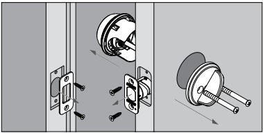
4 Remove the current deadbolt from the door.
Remove the entire deadbolt, including the bolt. You may also want to remove the strike.
- In order to maintain BHMA Grade 1, you must install the included reinforcement plate and strike (see step 7d on page 7).
- A standard Schlage deadbolt is shown. Check with your specific deadbolt manufacturer if you need help.
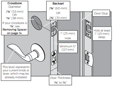
5 Check door/frame dimensions.
Measure the dimensions shown. If your door dimensions do not match, you will need to change your door preparation.
- If your door is thicker than 1C\v”, you will need a thick door kit. Please call Customer Service:
- Mark your crossbore and backset measurements on this page. You will need these measurements for installation. Either measurement is normal.
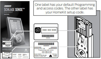
6 Locate programming and access codes.
Codes are located on the stickers on the front of the User Guide. You will need these codes to operate the lock. They are also located on the back of the Alarm Assembly.
- Do NOT remove these stickers from the back of your lock! If you lose your codes, you can reset your lock back to these default codes.
- The HomeKit setup code is used to connect your lock to your iPhone, iPad, or iPod touch.
7 Install bolt and strike.
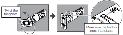
7a Adjust bolt length, if necessary.
- If the backset (see step 5 on page 5) of your door was 23/8” (60 mm), you do not need to do anything. Proceed to step step 7b.
- If the backset (see step 5 on page 5) of your door was 23/4” (70 mm), you need to adjust your bolt. Twist the faceplate until the button pops into the 23/4” space.
7b Change the faceplate, if necessary.
- In step 7c, your installation will depend on which kind of door edge you had in this step.
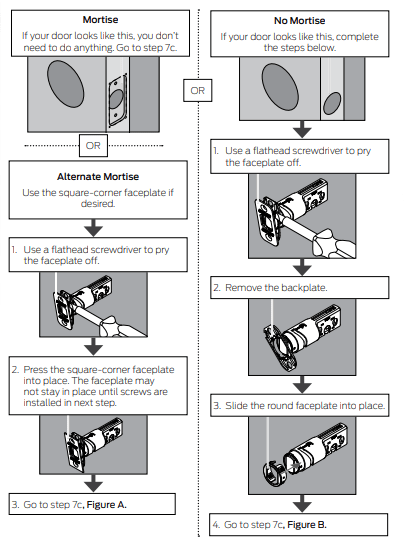
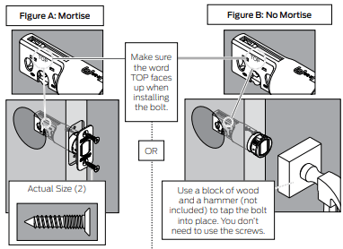
7c Install the bolt into the door.
Choose the picture below that matches your door.
7d Install the strike into the frame.
Install all the parts shown for maximum security.
- In order to maintain BHMA Grade 1, you must install the included reinforcement plate and strike.
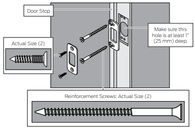
- The reinforcement screws may not fit on doors with sidelights.
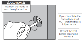
7e Test bolt alignment.
- Close the door.
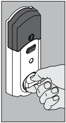
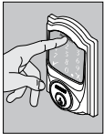
- Insert a flathead screwdriver into the slot in the bolt, as shown.
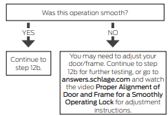
- Rotate the screwdriver toward the door edge to extend the bolt into the hole in the frame. This operation should be smooth. You should be able to rotate the screwdriver 90˚, fully extending the bolt.
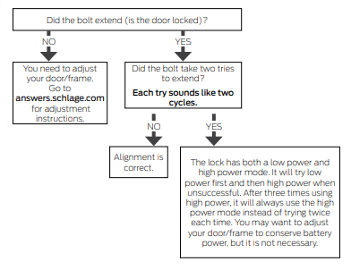
- If the operation was not smooth, or if the bolt did not fully extend, adjust your frame and/or door preparation. Go to answers.schlage.com and watch the video Proper Alignment of Door and Frame for a Smoothly Operating Lock for further instructions.
- Retract (unlock) the bolt before continuing to step 8.
If the deadbolt continues to rub against the strike, contact Customer Support for an alternate strike with an additional .060” (2 mm) clearance.
8 Install the Touchscreen Assembly.
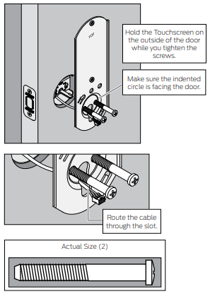
8a Install the Touchscreen on the outside of the door.
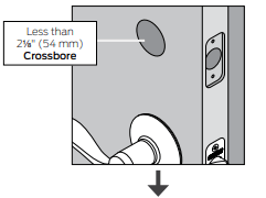
Always remove the spacer for a 11/2” (38 mm) crossbore. See Spacer Removal on page 14 before continuing.
- The clips snap into the crossbore (see step 5 on page 5) to assist in holding the keypad on the door.
- The Touchscreen Assembly should install smoothly. If it does not, check that the bolt is set to the correct backset (see step 7a on page 6).
- NOTE: If you have a crossbore (see step 5 on page 5) that is slightly less than 21/8” (54 mm), the lock may not install smoothly. You can remove the spacer.
8b Install the Support Plate on the inside of the door.
- Make sure the Touchscreen and Support Plate are straight on the door before tightening the screws. Tighten screws fully to prevent the lock from moving over time.
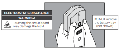
9 Install the Alarm Assembly.
9a Remove the battery cover from the Alarm Assembly.
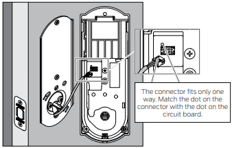
9b Connect the cable to the Alarm Assembly.
Locate the screws in step 9d before beginning this step so they will be handy when you need them.
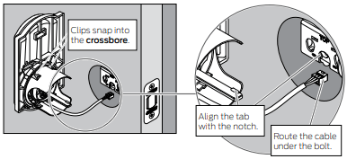
9c Install the Alarm Assembly.
1. Align the tab with the notch as shown.
2. Route the cable into the channel.
3. Then slide the Alarm Assembly toward the door.
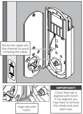
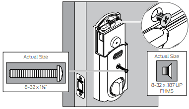
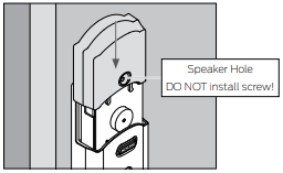
9d Secure the Alarm Assembly to the Support Plate.
Install the lower screw first.
NOTE Please do not rotate the thumbturn at this time. It may not rotate easily. Setup will be performed after installation is complete.
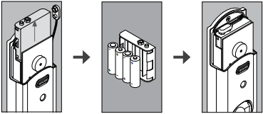
10 Install the Batteries.
10a Install the batteries into the battery tray.
1. Unsnap the connector.
2. Remove the battery tray.
3. Install four high-quality alkaline AA batteries.
- Lithium batteries may cause undesirable operation.
4. Carefully replace the battery tray, with the batteries facing the door.
5. Snap the connector back into place.
10b Install the battery cover.
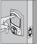
11 Set up the Lock.
1. Open the door if it is not already open.
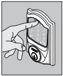
2. Press the Outside Schlage Button.
3. Enter one of the default access codes into the lock (see label shown in step 6 on page 5).
4. The lock will perform a setup routine. Wait until the bolt stops moving before continuing.
If the Touchscreen did not light up during this step, you may have a power problem. Install fresh batteries and make sure the battery wires are connected (see step 10a on page 11). If that does not help, make sure the cable is connected and is not crimped (see step 9b on page 10).
12 Test the Lock.
CAUTION Keep the key with you during testing to avoid being locked out!
For complete information about programming and light/beep patterns, see the Manual Programming Guide and Troubleshooting sections in the User Guide.
12a Extend the bolt (lock) using the inside thumbturn.
1. Close the door.
2. Rotate the thumbturn toward the door jamb to extend the bolt.
12b Extend the bolt (lock) using the Touchscreen.
1. Unlock the door using the thumbturn if you have not already.
2. Take the key and the default access codes with you! Go outside and close the door.
3. Press the Outside Schlage Button.
4. The bolt should extend.
12c Retract the bolt (unlock) using the Touchscreen.
1. Press the Schlage button.
2. Enter one of the default access codes into the lock.
3. The bolt should retract.
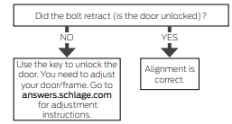
12d If the lock failed to lock or unlock:
1. If the Touchscreen did not light up, you may have a power problem. Install fresh batteries and make sure the battery connector is connected (see step 10a on page 11). If that does not help, make sure the cable is connected to the Alarm Assembly and is not crimped (see step 9b on page 10).
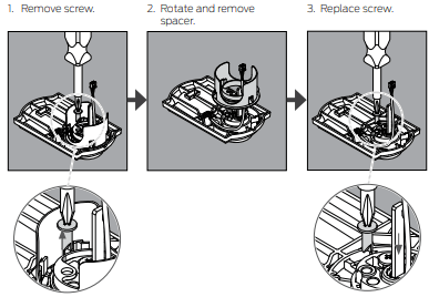
Spacer Removal
(Option for small crossbores only)
ONLY if your door has less than a 2Z\,” (54 mm) crossbore, remove the spacer as shown.
13 Continue to the User Guide.
Your lock is installed and functional. Continue to the User Guide for complete information about how to configure and operate the lock and alarm.