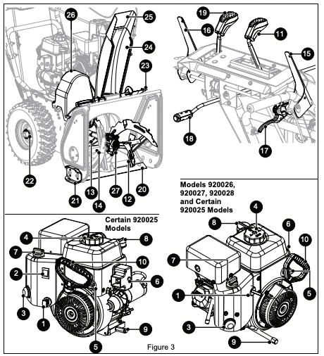
CONTROLS & FEATURES
1. Engine Key
2. Engine Run / Stop Switch
3. Primer Bulb
4. Fuel Tank and Cap
5. Fuel Valve
6. Electric Start Button
7. Choke Control Knob
8. Oil Fill / Dipstick
9. Oil Drain
10. Recoil Starter Handle
11. Speed Selector Lever
12. Auger
13. Impeller
14. Shear Bolt (2)
15. Attachment Clutch Lever
16. Traction Drive Clutch Lever
17. Height Adjustment Lever (Model 920028)
18. Discharge Chute Rotation Lever
19. Discharge Chute Deflector Lever
20. Scraper Blade
21. Skid Shoe (2)
22. Axle Lock Pin (2) (Models 920025, 920026, 920027)
23. Snow Clean-out Tool
24. Discharge Chute
25. Discharge Chute Deflector
26. Belt Cover
27. Gearcase
 WARNING: Read and understand the Safety section before proceeding.
See Figure 3 for all controls and features locations.
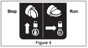
ENGINE KEY
Models 920026, 920027, 920028 and Certain 920025 Models
See Figure 4. Controls power to the engine. The key cannot be removed when in run position.
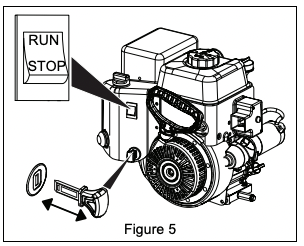
ENGINE KEY AND RUN / STOP SWITCH
Certain 920025 Models
See Figure 5. The removable engine key and the run / stop switch are used together to start the engine. The engine key must be inserted and in the run position for engine to start.
PRIMER BULB
Adds fuel to engine for easier start on cold engines.
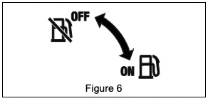
FUEL VALVE
See Figure 6. Controls fuel flow to the engine.
ELECTRIC START BUTTON
Starts a correctly choked engine.
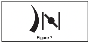
CHOKE CONTROL KNOB
See Figure 7. Controls airflow to the engine.
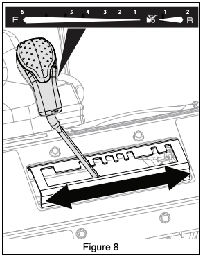
SPEED SELECTOR LEVER
See Figure 8. Controls the speed of forward and reverse travel.
AUGER
Rotates to bring snow into impeller.
IMPELLER
Throws snow out discharge chute.
SHEAR BOLT
Secures auger to shaft and helps prevent gearcase and gearcase component damage.
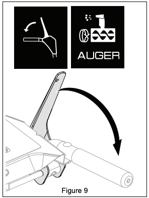
ATTACHMENT CLUTCH LEVER (RIGHT SIDE)
See Figure 9. Controls auger / impeller movement.
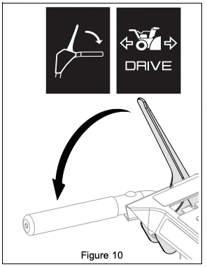
TRACTION DRIVE CLUTCH LEVER (LEFT SIDE)
See Figure 10. Allows unit to travel forward and in reverse.
DUAL HANDLE INTERLOCK
Allows auger / impeller to rotate without holding attachment clutch lever continuously. Auger continues to turn until both clutch levers are released.
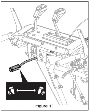
DISCHARGE CHUTE ROTATION LEVER
See Figure 11. Rotates discharge chute left or right to control snow discharge.
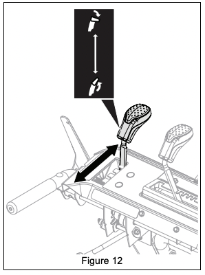
DISCHARGE CHUTE DEFLECTOR LEVER
See Figure 12. Moves discharge deflector up or down to control height of snow discharge.
SCRAPER BLADE
Contacts the surface being cleared and protects the housing from damage during normal use.
SKID SHOE
Controls the distance between the scraper blade and the surface.
AXLE LOCK PIN
Models 920025, 920026, 920027
Engages or disengages wheels with axle rotation, allowing for wheel drive or freewheeling. See Set Axle Lock Pin on page 13.
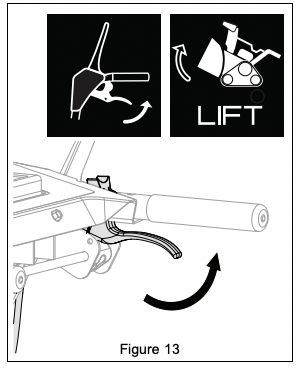
HEIGHT ADJUSTMENT LEVER (RIGHT SIDE)
Model 920028
See Figure 13. Raises or lowers auger housing for various snow-clearing situations.
OPERATION
WARNING: AVOID INJURY. Read and understand the Safety section before proceeding.
IMPORTANT: All references to left, right, front or rear are given from the perspective of operator in operator’s position, facing the direction of forward travel.
EMERGENCY STOPPING
1. Release both clutch levers.
2. Models 920026, 920027, 920028 and Certain 920025 Models: Turn engine key to stop position and remove key. Certain 920025 Models: Set engine switch to stop position and remove engine key from unit.
3. Wait for all moving parts to stop before leaving operator’s position.
BEFORE OPERATING UNIT
1. Check for a frozen impeller.
- a. Models 920026, 920027, 920028 and Certain 920025 Models: Turn engine key to stop position and remove key. Certain 920025 Models: Remove key and set engine switch to stop position.
- b. Engage attachment clutch lever and pull recoil starter handle.
- c. If handle does not pull, move unit to a warm area to thaw.
2. Check fuel level and add fuel if needed.
IMPORTANT: Use fresh unleaded fuel with an octane rating of at least 87. DO NOT use E85 blended fuels; the engine is not E20 / E30 / E85 compatible. The maximum recommended ethanol content is 10%. Ariens recommends using a quality fuel stabilizer in all fuel. See Short Term on page 27.
3. Check engine oil level and add oil if needed. Refer to engine manual.
4. Check function of controls.
• Attachment Clutch Lever
• Traction Drive Clutch Lever
• Dual Handle Interlock
5. Know how to stop in an emergency. See Emergency Stopping on page 11.
START THE ENGINE
1. Electric Start: Connect power cord to starter and then into 120V 3-wire grounded outlet. IMPORTANT: Use a power cord that is UL listed or CSA certified, rated for a minimum of 13 amps, grounded and labeled as suitable for outdoor use.
All Models
2. Turn fuel valve to on position.
3. Models 920026, 920027, 920028 and Certain 920025 Models: Turn engine key to run position.
Certain 920025 Models: Insert engine key and set engine switch to run position.
4. Cold Engines Only: Press primer bulb 3 times.
5. Turn choke control knob to on position.
6. Electric Start: Press electric start button.
NOTICE: DO NOT run starter more than 10 times at intervals of 5 seconds on / 5 seconds off or overheating and damage may occur.
7. Recoil Start: Pull recoil starter handle.
- a. Grasp handle and pull rope out slowly until it pulls harder.
- b. Pull handle firmly and quickly with a rapid, continuous full-arm stroke. Repeat until engine starts. If engine does not start, see Troubleshooting on page 25.
- c. Let handle rewind slowly after engine starts. DO NOT let handle snap against engine.
8. Gradually turn choke off as engine warms.
9. Electric Start: Disconnect power cord from outlet and then from starter.
OPERATE UNIT
1. Rotate discharge chute and move deflector to desired positions.
2. Select desired speed.
3. Engage attachment clutch.
NOTICE: Stop auger when traveling between work areas.
4. Engage traction drive clutch.
NOTICE: Release lever before changing speed.
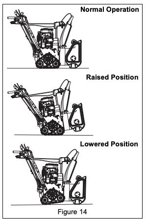
Adjust Track Angle
Model 920028
See Figure 14. To clear snow on gravel or uneven surfaces or to travel between work areas, squeeze height adjustment lever and push down on handlebars to raise auger housing. To clear packed snow, squeeze lever and lift up on handlebars to lower housing.
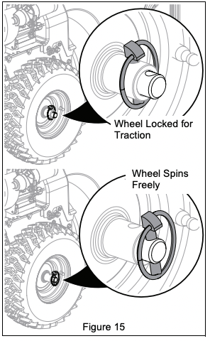
Set Axle Lock Pin
Models 920025, 920026, 920027
NOTICE: Wheels must be locked in the outer axle holes when using tire chains. See Figure 15. Axle lock pins may be positioned so both wheels lock with axle rotation for greater traction, or so one wheel is unlocked from axle and rotates freely for easier turning.
For greater traction:
1. Align both wheel hub holes with inner axle holes and insert lock pins.
For easier right turns:
1. Remove lock pin from right wheel hub.
2. Insert lock pin through outer axle hole.
For easier left turns:
1. Remove lock pin from left wheel hub.
2. Insert lock pin through outer axle hole.
CAUTION: One wheel MUST be locked with axle at all times.
Clear a Clogged Discharge Chute
WARNING: NEVER use your hand to clean out discharge chute.
1. Stop engine, remove key and wait for all moving parts to stop and for hot parts to cool.
2. Use the snow clean-out tool to clear the clog.
3. Return the tool to its storage position on the auger housing.
STOP THE ENGINE
1. Release traction drive clutch lever.
2. Run auger / impeller for a few minutes to remove loose or melting snow to prevent impeller from freezing.
3. Release attachment clutch lever.
4. Models 920026, 920027, 920028 and Certain 920025 Models: Turn engine key to stop position and remove key.
Certain 920025 Models: Stop engine and remove key from unit.
5. Turn fuel valve to off position.
TRANSPORT UNIT
1. Stop engine, remove key and close fuel valve.
2. Secure unit chassis to transport vehicle.
NOTICE: NEVER secure from rods or linkages that could be damaged.
MAINTENANCE
WARNING: Read and understand the Safety section before proceeding.
Your Ariens dealer can provide service and adjustments to keep your unit operating at peak efficiency. Contact an authorized engine manufacturer’s service center for engine service.
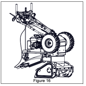
SERVICE POSITION
See Figure 16.
WARNING: AVOID INJURY. Before tipping unit, close fuel valve and drain fuel from tank and fuel system. (Refer to engine manual for instructions.) Make sure unit is secure and will not tip.
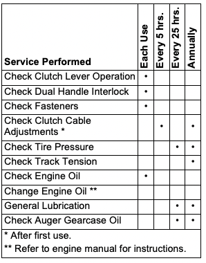
MAINTENANCE SCHEDULE
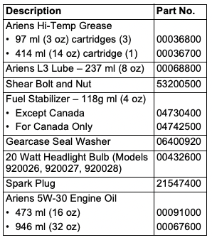
SERVICE PARTS
See your Ariens dealer to purchase service parts for your unit.
CHECK DUAL HANDLE INTERLOCK
1. Stop engine.
2. Engage attachment clutch and then the traction drive clutch.
3. Release the attachment clutch lever. The attachment clutch should stay engaged until the traction drive clutch lever is released.
IMPORTANT: If dual handle interlock does not operate correctly, adjust or repair as directed in the service guide for your unit.
CHECK FASTENERS
Check for loose hardware.
CHECK CLUTCH CABLE ADJUSTMENTS
Auger / impeller must stop within 5 seconds when attachment clutch lever is released.
Wheels must stop quickly when traction drive clutch lever is released.
If clutches do not engage or disengage correctly, see Adjust Attachment Clutch & Brake on page 20 or Adjust Traction Drive Clutch on page 23. Refer to the service guide for your unit for more information about clutch repairs
CHECK TIRE PRESSURE
Models 920025, 920026, 920027
Keep tires inflated to pressure listed on tire sidewall.
WARNING: AVOID INJURY. Explosive separation of tire and rim parts is possible.
• DO NOT inflate tires above the recommended pressure.
• DO NOT inflate tires with a compressor; use a hand pump.
• DO NOT stand in front of tire assembly when inflating. Use a clip-on chuck and extension hose long enough to allow you to stand to one side.
• DO NOT mount a tire without proper equipment and experience.
CHECK ENGINE OIL
NOTICE: Engine oil level must be maintained at correct level or engine damage may occur. Refer to engine manual.
CHANGE ENGINE OIL
Refer to engine manual.
CHECK AUGER GEARCASE OIL
1. Place unit on flat, level surface.
2. Remove oil fill plug and seal washer. See Figure 17.
IMPORTANT: DO NOT remove gearcase cover.
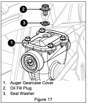
3. Check oil level with a suitable measuring device, such as a clean screwdriver and add oil if needed. Oil level must be 4.1 cm – 4.8 cm (1.6" – 1.9") from the flat surface of the gearcase cover.
IMPORTANT: Ariens recommends using only Ariens L3 synthetic severe duty gear lube (see Service Parts on page 14). Using other lubricants will not automatically void unit warranty, but the warranty will not cover damage caused by using unauthorized lubricants.
4. Inspect seal washer for wear or rubber deterioration and replace if needed.
5. Reinstall seal washer (rubber side down) and oil fill plug. Torque to 9 N•m (80 lb-in).
IMPORTANT: DO NOT over torque. Measurements are given in pound force inches (lb-in) and not pound force foot (lb-ft).
IMPORTANT: Incorrect torquing and failure to install or correctly torque seal washer may void gearcase warranty.
LUBRICATE UNIT
Ariens recommends using Ariens Hi-Temp Grease or equivalent (see Service Parts) to lubricate fittings. Lubricate each season or every 25 hours of operation.
IMPORTANT: Wipe each fitting clean before and after lubrication.
Remove Bottom Cover
Models 920025, 920026, 920027
1. Place unit in service position. See Figure 16.
2. Remove six hex bolts retaining cover and remove cover. Save for reinstallation.
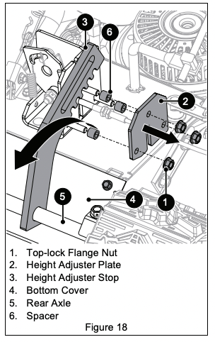
Model 920028
See Figure 18.
1. Place unit in service position. See Figure 16.
2. Remove three top-lock flange nuts retaining height-adjuster plate to heightadjuster bracket.
3. Remove height-adjuster plate and three spacers on the round head square neck bolts. The height-adjuster stop will be attached to the rear axle.
4. Slide height-adjuster stop to the right and rotate it away from frame.
NOTICE: The track carriage will rotate freely without the height-adjuster bracket. Keep fingers and hands away from pinch points.
5. Remove six bolts retaining bottom cover and remove cover. Rotate track carriage as needed to remove cover.
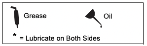
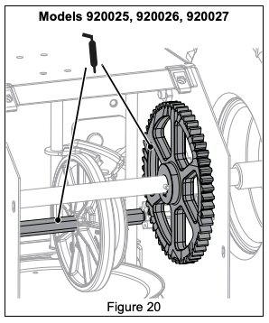
Lubricate Unit
Use the following key for all lubrication procedures.
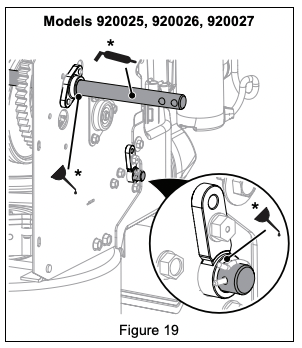
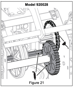
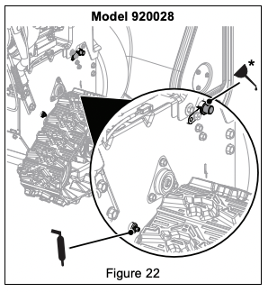
Traction Drive
1. Lubricate as shown in Figures 19, 20, 21 and 22.
IMPORTANT: DO NOT allow grease or oil to contact friction disc, friction plate or belts.
2. Reinstall bottom cover and return unit to operating position.
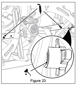
Auger Shaft
See Figure 23.
1. Remove shear bolt nuts and bolts.
2. Apply grease at the grease zerks.
3. Hand rotate auger on auger shaft.
4. Align shear bolt holes in auger with shear bolt holes in shaft.
5. Insert bolts through holes.
6. Secure bolts with nuts.
7. Tighten bolts to 7.9 N•m – 16.5 N•m (5.8 lb-ft – 12.2 lb-ft). If a torque wrench is unavailable, tighten bolts until they no longer spin freely. DO NOT overtighten.
ADJUSTMENTS
WARNING: AVOID INJURY. Read and understand the Safety section before proceeding.
ADJUST SCRAPER BLADE
The auger housing may be damaged if blade wears down too much.
1. Tip unit back onto handlebar, support auger housing and loosen nuts retaining blade.
2. Lower blade and tighten nuts.
3. Adjust skid shoes. See Adjust Skid Shoes on page 18.
NOTICE: ALWAYS adjust skid shoes after adjusting blade to prevent premature wear of blade and auger housing damage.
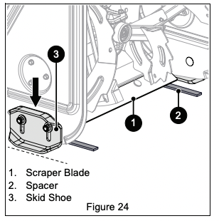
ADJUST SKID SHOES
See Figure 24.
1. Place unit on a hard, flat surface.
2. Place a spacer under each scraper blade end.
• Use two 3 mm (1/8") thick spacers for hard, smooth surfaces.
• Use two 13 mm (1/2") thick spacers for uneven or gravel surfaces.
3. Loosen skid shoe hardware and lower skid shoes to contact surface. Adjust both shoes equally.
4. Tighten skid shoe hardware.
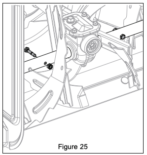
REPLACE SHEAR BOLTS
IMPORTANT: Ariens recommends using only Ariens OEM shear bolts when replacing shear bolts. See Figure 25.
1. Align shear bolt holes in auger with shear bolt holes in the shaft.
2. Insert bolts through holes.
3. Secure bolts with nuts.
4. Tighten bolts to 7.9 N•m – 16.5 N•m (5.8 lb-ft – 12.2 lb-ft). If a torque wrench is unavailable, tighten bolts until they no longer spin freely. DO NOT overtighten
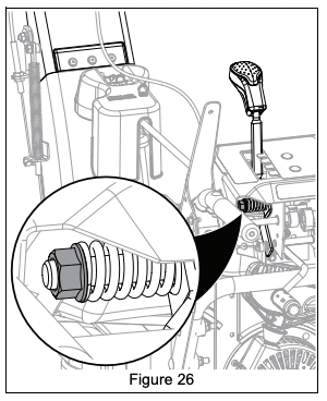
ADJUST DISCHARGE CHUTE DEFLECTOR LEVER
See Figure 26. If deflector does not stay in selected position, tighten the nut under the control panel.
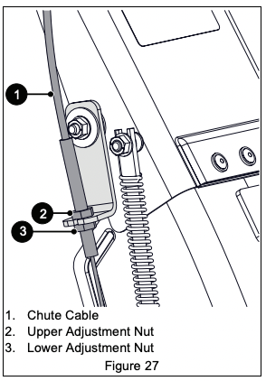
If deflector does not follow full range of travel:
1. Position deflector control in the rear-most position.
2. Adjust nuts on chute cable. See Figure 27.
• To adjust deflector lower, loosen lower nut and tighten upper nut.
• To adjust deflector higher, loosen upper nut and tighten lower nut.
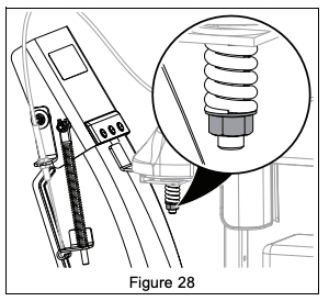
ADJUST DISCHARGE CHUTE
See Figure 28.
If discharge chute does not stay in selected position, tighten nut on carriage bolt.
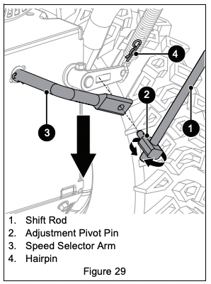
ADJUST SPEED SELECTOR LEVER
See Figure 29.
1. Disconnect adjustment pivot pin from speed selector arm. Save hardware for reinstallation.
2. Position speed selector lever in fastest forward position.
3. Turn speed selector arm down as far as it will go.
4. Models 920025, 920026, 920027: Thread adjustment pivot pin along shift rod until it aligns with the mating hole on the speed selector arm, and then turn it up the shift rod 7 turns. Insert pivot pin into the hole.
5. Model 920028: Thread adjustment pivot pin along shift rod until it aligns with the mating hole on the speed selector arm, and then turn it up the shift rod 3 turns. Insert pivot pin into the hole.
6. Connect pivot pin to speed selector arm with hardware removed in step 1 and check forward and reverse speeds.
- a. Start unit, position speed selector lever in the first forward position and engage traction drive clutch. Unit should move forward.
- b. Stop unit, position speed selector lever in the first reverse position and engage traction drive clutch. Unit should move in reverse.
- c. Stop unit. If unit does not travel correctly, repeat adjustments.
ADJUST ATTACHMENT CLUTCH & BRAKE
WARNING: AVOID INJURY. Improper adjustment could result in unexpected movement of auger and impeller causing death or serious injury. AUGER / IMPELLER MUST STOP within 5 seconds when attachment clutch lever is released.
Remove Slack from Attachment Cable
1. Stop engine, remove key and wait for all moving parts to stop and for hot parts to cool.
2. Disconnect spark plug wire.
3. Loosen hardware securing belt cover to unit and remove belt cover.
IMPORTANT: DO NOT completely remove hardware from unit.
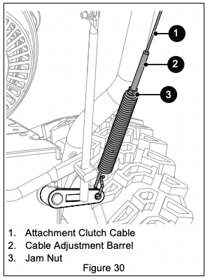
4. Loosen jam nut on cable adjustment barrel, and then turn the adjustment barrel down to shorten cable and remove cable slack. See Figure 30.
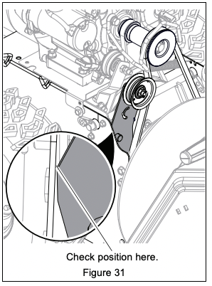
5. With the attachment clutch disengaged, make sure auger idler arm lightly touches the frame. See Figure 31.
6. Tighten jam nut on cable adjustment barrel. See Figure 30.
7. Reinstall belt cover and tighten hardware.
8. Reconnect spark plug wire.
Check Attachment Idler Arm Roller Clearance
1. Place unit in service position and remove bottom cover. See Remove Bottom Cover on page 16.
2. Engage attachment clutch and check the clearance between the frame and plastic roller on the lower end of the attachment idler arm. Roller should be 12.7 mm – 22.2 mm (1/2" – 7/8") from the frame. See Figure 32.
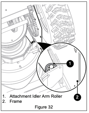
• If roller is 12.7 mm – 22.2 mm (1/2" – 7/8") from frame, no further adjustment is required.
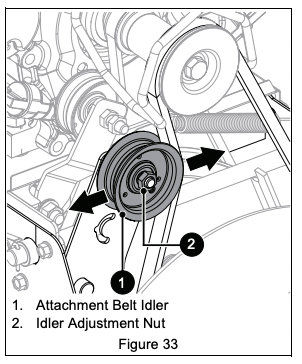
• If roller is less than 12.7 mm (1/2") from frame, loosen idler adjustment nut and move idler closer to belt. Tighten adjustment nut and recheck roller clearance. See Figure 33.
• If roller is more than 22.2 mm (7/8") from frame, loosen idler adjustment nut and move idler away from belt. Tighten adjustment nut and recheck roller clearance. See Figure 33.
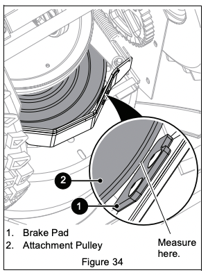
Check Attachment Brake
With the attachment clutch disengaged, brake pad must contact attachment belt or pulley, whichever is closest. With attachment clutch engaged, brake pad must be a minimum of 1.6 mm (1/16") from belt or pulley.
• If there is less than 1.6 mm (1/16") gap, loosen idler adjustment nut and move idler away from belt or pulley. Position idler to achieve a 1.6 mm (1/16") minimum brake pad gap and a 12.7 mm – 22.2 mm (1/2" – 7/8") gap between the plastic roller and the frame. See Figure 34.
IMPORTANT: If adjustments cannot be brought into specified ranges, see your dealer for repair.
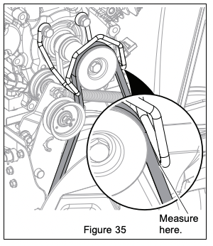
Check Belt Finger Clearance
See Figure 35. With attachment clutch engaged, the belt finger located opposite the belt idler must be less than 3.2 mm (1/8") from belts, but must not touch the belts.
To adjust belt finger:
1. Remove belt cover.
2. Loosen bolts and move belt finger to correct position.
3. Tighten bolts and recheck belt finger clearance.
4. Reinstall belt cover and tighten hardware.
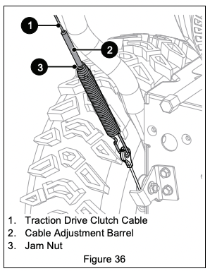
ADJUST TRACTION DRIVE CLUTCH
See Figure 36. If unit does not drive correctly, adjust traction clutch to compensate for friction disc wear.
1. Stop engine, remove key and wait for all moving parts to stop and for hot parts to cool.
2. Disconnect spark plug wire.
3. Loosen jam nut on traction cable adjustment barrel, and then turn adjustment barrel down to shorten cable and remove cable slack.
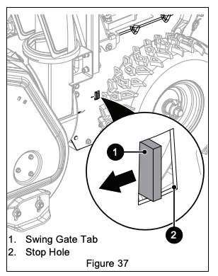
4. With traction clutch disengaged, check that swing gate tab touches the front edge of stop hole. See Figure 37.
IMPORTANT: Swing gate tab MUST touch stop hole edge. Readjust cable as necessary until tab touches stop hole edge.
5. Reconnect spark plug wire.
TROUBLESHOOTING
Engine will not start.
Engine key in stop position. (Models 920026, 920027, and Certain 920025 Models)
- Turn engine key to run position. See Engine Key on page 9.
Engine switch is in off position.(Certain 920025 Models)
- Push switch to on position. See Engine Key and Run / Stop Switch on page 9.
Choke is off.
- Turn choke control knob to on position.See Choke Control Knob on page 9.
Fuel valve is closed.
- Open valve. See Fuel Valve on page 9.
Fuel tank is empty.
- Fill tank with fuel. See Before Operating Unit on page 11.
Engine is not primed.
- If engine is cold, press primer bulb three times and start engine. Do not prime a warm engine. See Primer Bulb on page 9.
Ignition switch starter circuit is not functioning. (Electric start)
- See your dealer for repair.
Build up of dirt and residue around governor / carburetor.
- Clean area around governor / carburetor. See the service guide for your unit.
Spark plug wire is disconnected.
- Connect spark plug. Refer to engine manual.
Spark plug is faulty.
- Replace spark plug. Refer to engine manual.
Excessive fuel in engine cylinder (flooded).
- Turn choke control knob to off position and reattempt starting. See Start The Engine on page 12.
Engine is faulty.
- See your Ariens dealer or authorized engine manufacturer’s service center.
Engine starts hard or runs poorly.
Fuel mixture is too rich.
- Turn choke control knob to off position. See Choke Control Knob on page 9.
Spark plug is faulty, fouled or incorrectly gapped.
- Clean and correctly set spark plug gap refer to engine manual) or see your Ariens dealer.
Fuel cap vent is blocked.
Engine stops.
Fuel tank is empty.
- Fill tank with fuel. See Before Operating Unit on page 11.
Fuel valve is closed.
- Open valve. See Fuel Valve on page 9.
Obstruction in auger or impeller.
- Stop engine, remove key and wait for all moving parts to stop. Check for and remove obstruction before restarting.
Contaminated fuel supply.
Spark plug is faulty.
- Replace or clean spark plug. Refer to engine manual.
Fuel cap vent is blocked.
Unit runs briefly then stops.
A build up of fumes in the fuel tank is creating too much pressure in the fuel tank.
- Slowly loosen the fuel tank cap.
Unit does not drive forward or in reverse.
Friction disc is worn.
- Replace friction disc. Refer to the service guide for your unit.
Traction drive cable is not adjusted correctly.
- Remove slack from cable. See Adjust Traction Drive Clutch on page 23.
Traction belt is not functioning.
- Repair or replace traction drive belt. Refer to the service guide for your unit.
Speed selector is not adjusted correctly.
- Adjust speed selector. See Adjust Speed Selector Lever on page 20.
Unit does not throw snow or throws it poorly.
Shear bolts are broken.
- See Replace Shear bolts on page 18.
Attachment clutch / brake is not adjusted correctly.
- See Adjust Attachment Clutch & Brake on page 20.
Impeller is frozen in place.
- Move unit to a warm place to thaw.
Ice or debris is obstructing auger.
- Stop engine, remove key and wait for moving parts to stop. Check for and remove obstruction before restarting.
Discharge chute is clogged with snow.
- Stop engine, remove key and wait for all moving parts to stop and for hot parts to cool. Clean discharge chute and auger housing with clean-out tool. DO NOT use your hands.
Auger drive belt is slipping, worn or damaged.
- Adjust or replace auger drive belt. Refer to the service guide for your unit.
Auger drive belt is loose or damaged.
- Replace belt or adjust auger control cable. Refer to the service guide for your unit.
Excessive snow is left behind.
Scraper blade is worn or damaged.
- Adjust when worn and replace when damaged or when blade has been adjusted down as far as possible and does not touch ground or clear correctly. See Adjust Scraper Blade on page 18.
Small rubber beads collect in frame.
Friction disc wear.
- This is normal friction disc wear and no correction is needed unless there are chunks or large pieces of rubber collecting in frame. If repair is needed, refer to the service guide for your unit.
STORAGE
WARNING: AVOID INJURY. Read and understand the Safety section before proceeding.
SHORT TERM
1. Run auger / impeller for a few minutes to remove loose or melting snow and prevent impeller from freezing.
2. Tighten all hardware to correct specifications.
3. Inspect unit for visible signs of wear or damage. Repair as needed.
4. Apply a light layer of oil or anti-rust compound on bare metal areas.
5. Prepare fuel system for storage.
NOTICE: Ariens recommends using a quality fuel stabilizer in all fuel. Gasoline left in the fuel system without a stabilizer, even for short periods of time, deteriorates and leaves gummy deposits in the system that may damage the carburetor and fuel hoses, filter and tank. For the best effectiveness, add stabilizer to all fuel containers whenever purchasing fuel. Add the stabilizer to the container before adding fuel.
- a. Add Ariens fuel stabilizer (see Service Parts on page 14) or equivalent according to manufacturer's instructions to the fuel tank and any fuel containers with remaining fuel.
- b. Run engine outdoors for at least 5 minutes to allow stabilizer to reach the carburetor.
6. Close fuel valve and allow engine to stop on its own.
7. Turn engine key to stop position and remove key.
8. Store unit in a cool, dry, protected area. Do not store unit outdoors.
LONG TERM
1. Perform all short-term storage items.
2. Wash salt and other corrosive ice-melting agent residue from unit with mild soap and low-pressure water.
IMPORTANT: Never spray unit with highpressure water.
3. Lubricate as directed in Maintenance on page 14.
4. Touch up all scratched painted surfaces.
5. Remove weight from wheels by putting blocks under frame or axle.
6. Store unit in a cool, dry, protected area. Do not store unit outdoors.
START-OF-SEASON FUEL PREPARATION
Before opening the fuel valve for the first time after long-term storage, add fresh, stabilizertreated fuel to the fuel tank and any fuel containers with remaining fuel.