User Manual Snow Blowers
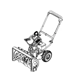
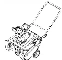
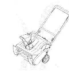
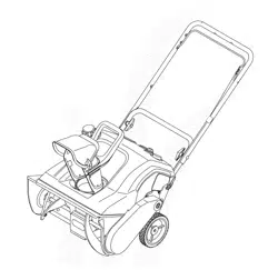
CONTROLS & FEATURES
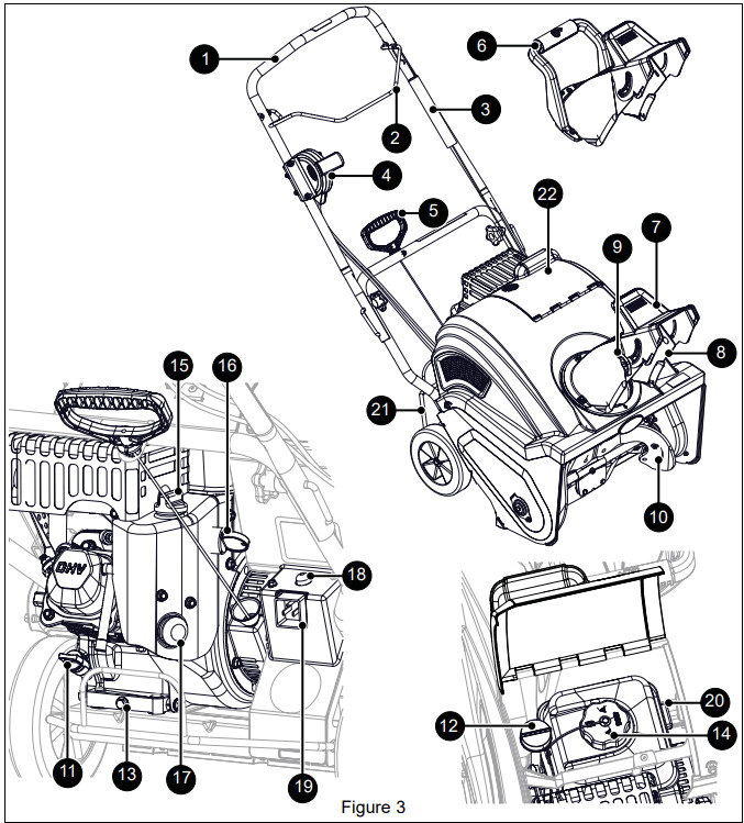
- Handlebar
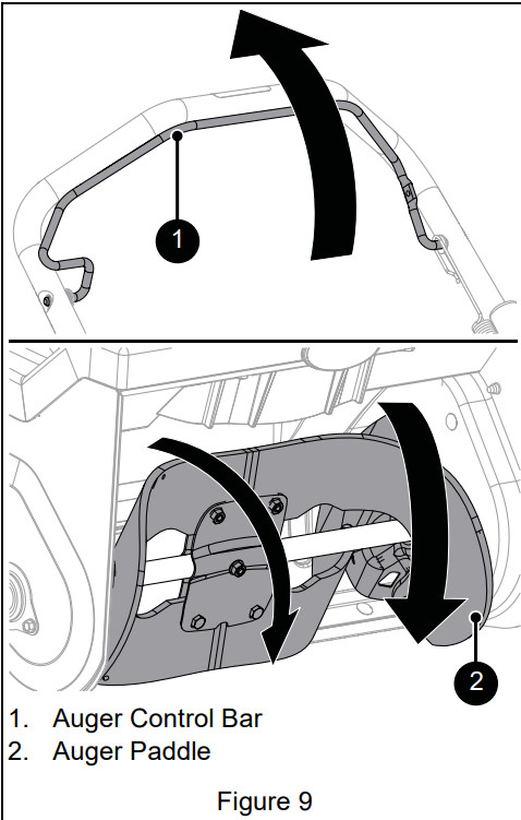
- Auger Control Bar
- Auger Control Cable Assembly
- Remote Discharge Chute Handle Assembly (Model 938033)
- Recoil Starter Handle
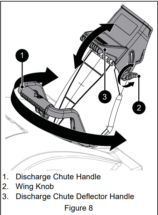
- Discharge Chute Handle (Models 938030, 938031, 938032, 938034)
- Discharge Chute Deflector Handle
- Discharge Chute
- Wing Knob
- Auger Paddle
- Oil Fill (Models 938030, 938034)
- Oil Fill (Models 938031, 938032, 938033)
- Oil Drain Plug
- Fuel Cap & Tank
- Choke Control Knob
- Engine Switch
- Primer Bulb
- Electric Start Button (Models 938032, 938033, 938034)
- Power Cord Receptacle (Models 938032, 938033, 938034)
- Fuel Valve
- Engine Guard
- Fuel & Oil Door
WARNING: AVOID INJURY. Read and understand the Safety section before proceeding.
See Figure 3 for all controls and features locations.
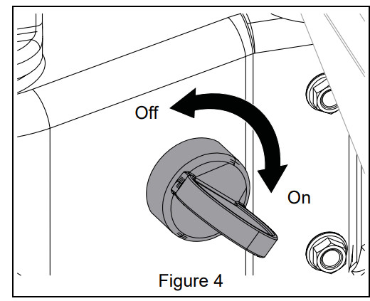
ENGINE SWITCH
The engine switch has two positions:
- Off – Engine will not start or run.
- On – Engine will start and run.
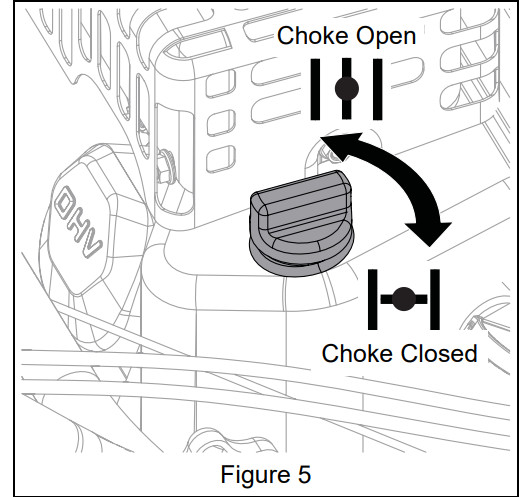
CHOKE CONTROL KNOB
- Start – (Choke Closed): Chokes off air to engine for easier starting.
- Run – (Choke Open): Allows for normal operation.
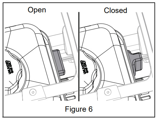
FUEL VALVE
Controls fuel flow to the engine. The fuel valve has two positions:
- Closed – Use this position to service, transport or store the unit.
- Open – Use this position to run the unit.
NOTICE: The valve is closed when it is narrow and vertical when viewed from above.
PRIMER BULB
Adds fuel to engine for easier start on cold engines. See Start Engine on page 10.
RECOIL STARTER HANDLE
When pulled, handle will start engine. See Start Engine on page 10.
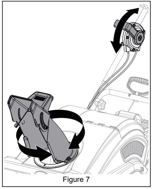
REMOTE DISCHARGE CHUTE HANDLE ASSEMBLY
Move remote discharge chute handle forward or backward to control direction of snow discharge.
BEFORE OPERATING
WARNING: AVOID INJURY. Read and understand the Safety section before proceeding
IMPORTANT: All references to left, right, front or rear are given from the perspective of operator in operator’s position, facing the direction of forward travel.
- Know how to stop in an emergency. See Emergency Stopping on page 10.
- Check for frozen components.
- Check fuel level and add fuel if needed.
- IMPORTANT: Use fresh unleaded fuel with an octane rating of at least 87. DO NOT use E85 blended fuels; the engine is not E20 / E30 / E85 compatible. The maximum recommended ethanol content is 10%. Ariens recommends using a quality fuel stabilizer in all fuel. See Short Term on page 17.
- Check engine oil level and add oil if needed. Refer to engine manual.
- Check function of all controls.
CHECK ENGINE OIL
Models 938031, 938032, 938033
- Stop engine, remove key and close fuel valve.
- Open fuel and oil door and remove cap from oil fill.
- Check engine oil level and add oil if needed. Refer to engine manual.
- Replace cap and close door.
- Clean up any spilled oil.
Models 938030, 938034
- Stop engine, remove key and close fuel valve.
- Remove cap from oil fill.
- Check engine oil level and add oil if needed. Refer to engine manual.
- Replace cap.
- Clean up any spilled oil.
OPERATION
WARNING: AVOID INJURY. Read and understand the Safety section before proceeding.
EMERGENCY STOPPING
- Release auger control bar.
- Turn engine switch to OFF position.
- Wait for all moving parts to stop before leaving operator’s position.
START ENGINE
- Position discharge chute in a safe direction. See Position Discharge Chute on page 11.
- Move engine switch to ON position.
- Electric Start Models Only: Connect a power cord to power cord receptacle and then plug cord into a wall outlet.
- CAUTION: Use cord that is minimum of 13 amp, 16 Gauge, 3 wire grounded plug, UL listed, CSA Certified. Cord must be labeled suitable for outdoor use.
- Open fuel valve.
- If engine is cold, turn choke to CLOSED position.
- IMPORTANT: Do not apply choke to a warm engine.
- Push primer bulb twice.
- IMPORTANT: Do not push primer bulb to start a warm engine.
- Electric Start Models Only: Press electric start button. If engine does not start after three attempts, see Troubleshooting on page 18.
- Electric Start Models Only: When engine starts, disconnect power cord from wall outlet, then disconnect cord from power cord receptacle.
- Recoil Start: Pull recoil starter handle.
- a. Grasp handle and pull rope out slowly until it pulls harder.
- b. Pull handle firmly and quickly with a rapid, continuous full-arm stroke. Repeat until engine starts. If engine does not start, see Troubleshooting on page 18.
- c. Let handle rewind slowly after engine starts. DO NOT let handle snap back against handlebar.
- Gradually open choke after engine starts.
POSITION DISCHARGE CHUTE
IMPORTANT: Always throw snow in a safe direction, away from people and windows.
IMPORTANT: If chute becomes frozen and does not turn correctly, take unit into warm area until controls are unfrozen.
OPERATE UNIT
- Rotate discharge chute and move deflector to desired positions.
- NOTICE: On some surfaces, auger paddle rotation may leave residual paddle material. This usually washes off after rain showers. Scraper bar may be adjusted to minimize this condition. See Adjust Scraper Blade on page 15.
- Pull auger control bar back to handlebar to start auger; release bar to stop auger. See Figure 9.
STOP ENGINE
- Release auger control bar.
- Turn engine switch to OFF position.
- Close fuel valve.
TRANSPORTING UNIT
- Stop engine, remove key and close fuel valve.
- NOTICE: Use extra care when loading or unloading onto truck or trailer. DO NOT lift using discharge chute handle.
- Secure unit chassis to transport vehicle. Never secure from rods or linkages that could be damaged.
FOR BEST PERFORMANCE
- For complete snow removal, walk slowly and slightly overlap each path previously taken.
- Position discharge chute downwind when possible.
- Do not pick up gravel and rocks. Push down slightly on handlebar to avoid picking up debris.
- Inspect auger before each use and remove any accumulation / debris.
- Check oil level before each use.
- Clean unit after each use.
MAINTENANCE
WARNING: AVOID INJURY. Read and understand the Safety section before proceeding
Proper maintenance can prolong the life of unit. The Maintenance Schedule on Page 12 shows the recommended service schedule. Your Ariens dealer can provide service and adjustments to keep your unit operating at peak efficiency. Contact an authorized engine manufacturer’s service center for engine service. More frequent service may be required due to working conditions (heavy loads, high ambient temperatures, dusty conditions, or airborne debris).
See the maintenance instructions in the Engine Manual for additional information.
MAINTENANCE SCHEDULE
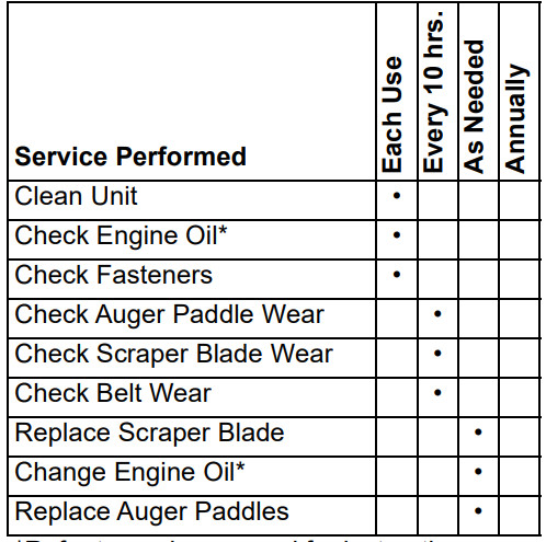
*Refer to engine manual for instructions.
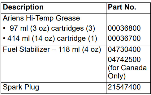
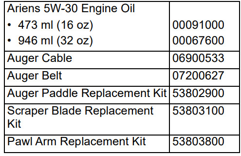
SERVICE PARTS
See your Ariens dealer to purchase service parts for your unit.
CLEAN UNIT
- Remove snow and debris with a softbristled brush. DO NOT use harsh abrasives or cleaners.
- Protect painted surfaces with automotivetype wax.
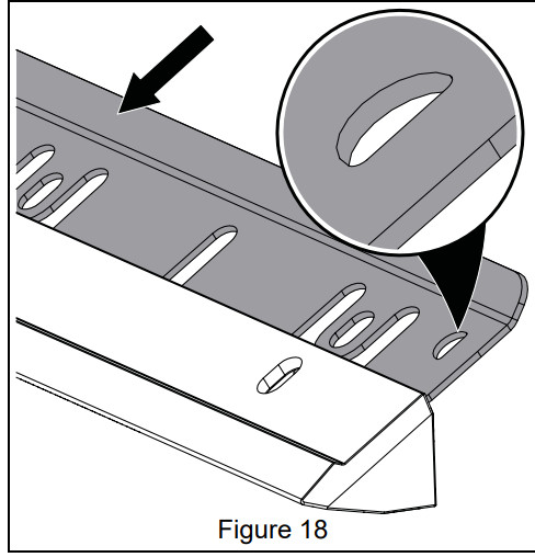
CHECK SCRAPER BLADE WEAR
Replace when damaged or when scraper blade has been adjusted down as far as possible and does not touch surface or clear properly. Scraper blade MUST be replaced when worn through to wear indicator pockets. See Figure 10.
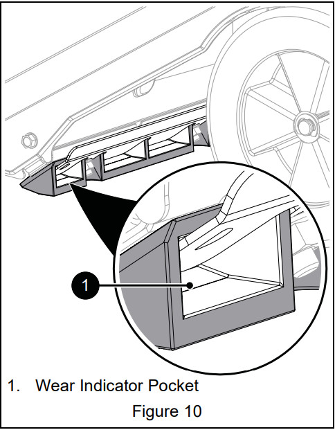
NOTICE: DO NOT allow scraper blade to wear down too far or auger housing will become damaged. See Replace Scraper Blade on page 15.
CHECK BELT WEAR
Adjust auger cable as needed. Replace when damaged or when auger stops or stutters during operation. See Adjust Auger Cable on page 14 and Replace Belt on Page 15.
SERVICE & ADJUSTMENTS
WARNING: AVOID INJURY. Read and understand the Safety section before proceeding.
REPLACE AUGER PADDLES
Replace auger paddles when paddles have worn completely through wear indicator holes. See Figure 11.
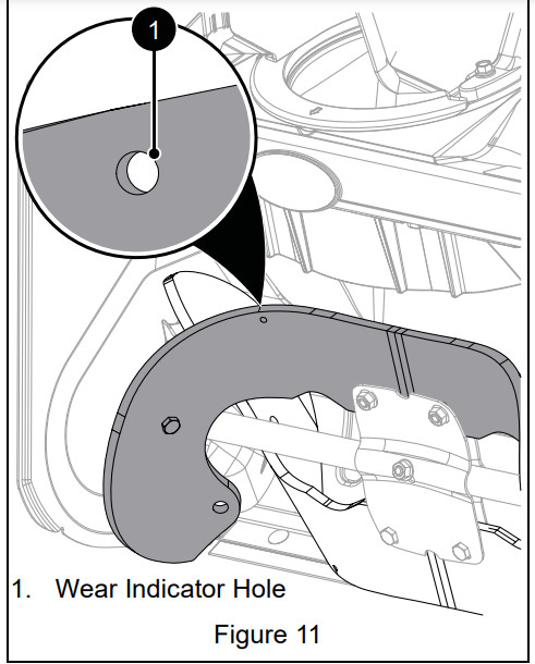
IMPORTANT: Always replace auger paddles in pairs. Do not replace one paddle only.
- Stop engine, remove key and close fuel valve. Allow unit to cool. See Figure 12.
- Tip unit back onto engine guard. DO NOT tip further than engine guard allows or oil may leak out of engine.
- Remove six hex bolts, washers and top locking flange nuts securing each paddle to center plate and side plates. Discard all parts.
- IMPORTANT: Do not remove center plate.
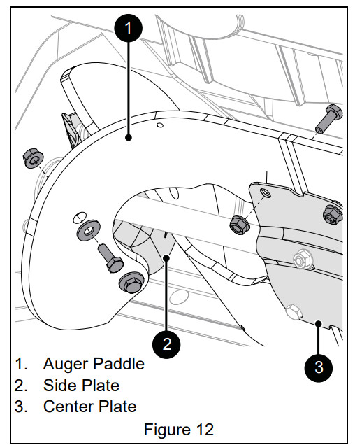
- Position new paddles with wear indicator holes on the left side as you face the unit.
- Install spacers into paddle holes and secure paddle with new hex bolts and nuts.
- Tighten nuts to 5.6 – 10.2 N•m (50 – 90 lb-in). DO NOT overtighten.
- When both paddles are installed, rotate auger paddles by hand. Ensure that paddles do not rub on housing and are tightly attached.
- Return unit to operating position.
- Remove slack from auger cable. See Adjust Auger Cable on page 14.
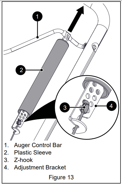
ADJUST AUGER CABLE
- Stop engine, remove key and close fuel valve.
- Slide plastic sleeve up to auger control bar.
- Insert Z-hook into appropriate hole in adjustment bracket. When auger control bar is disengaged, there should minor slack in cable and no tension.
- Engage auger control bar to ensure proper operation. There should be no excessive tension on cable.
- Lower plastic sleeve.
REPLACE BELT
- Stop engine, remove key and close fuel valve. Allow unit to cool.
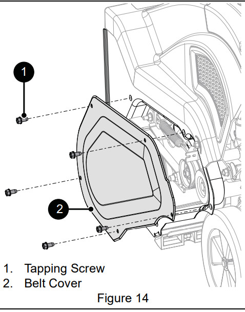
- Remove five tapping screws from belt cover and remove belt cover. Retain all parts. See Figure 14.
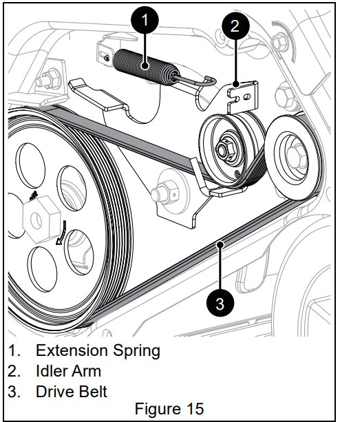
- Disconnect extension spring from idler arm.
- Remove belt from drive pulley, idler and engine sheave.
- Install new belt on engine sheave, idler and drive pulley. Route belt between idler and belt finger on idler arm.
- Reinstall extension spring.
- Reinstall belt cover.
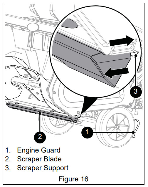
ADJUST SCRAPER BLADE
IMPORTANT: The auger housing may be damaged if blade wears down too much.
- Tip unit back onto engine guard and loosen hardware securing scraper blade to scraper support.
- Reposition scraper blade.
- Move scraper blade down to compensate for scraper blade wear and increase auger clearance.
- Move scraper blade up to decrease auger clearance.
- Tighten hardware and return unit to operating position.
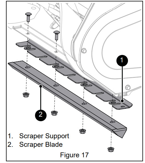
REPLACE SCRAPER BLADE
- Stop engine, remove key and close fuel valve. Allow unit to cool.
- Tip unit back onto engine guard.
- Remove nuts, bolts, scraper support and scraper blade. Retain hardware. Discard scraper blade.
- Check condition of scraper support. Replace if worn or damaged.
- Insert scraper support into new scraper blade. The D-shaped cutout must be on the left (drive belt side).
- Position scraper assembly under housing.
- D-shaped cutout must be on the left.
- Edge must point down and forward.
- Scraper assembly bolt holes must align with square bolt holes in auger housing.
- Move scraper assembly backward and up until small lip on top of scraper blade contacts bottom lip of housing.
- Install bolts and nuts. Tighten nuts to 4.5 – 5.7 N•m (40 – 50 lb-in). Threads must protrude beyond the nut.
- Return unit to operating position.
IMPORTANT: If auger paddles are pulling too strongly or scraper blade is not clearing completely, loosen nuts (do not remove) and slide scraper assembly down slightly. Tighten nuts.
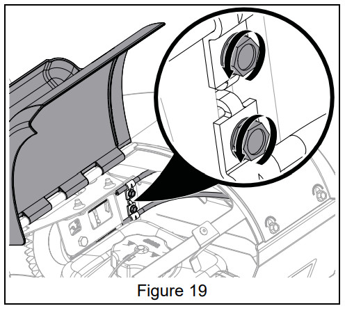
ADJUST REMOTE CHUTE ROTATION CABLES
- Stop engine, remove key and close fuel valve. Allow unit to cool. See Figure 19.
- Open fuel and oil door to access chute rotation cable adjustment screws.
- Loosen cable clamp screws.
- Pull cable covers to the right to remove slack.
- Tighten screws and close fuel and oil door.
NOTICE: Remote chute rotation cables may also be accessed from under unit by tipping unit forward.
TROUBLESHOOTING
- Engine will not start.
- Engine switch in OFF position.
- Move switch to ON position. See Engine Switch on page 9.
- Fuel valve is closed.
- Open fuel valve. See Fuel Valve on page 9.
- Fuel tank empty.
- Fill fuel tank with fuel. See Before Operating on page 10.
- Cord not plugged in (electric start models only).
- Plug power cord in or replace worn cord. Reset circuit breaker.
- Engine not primed.
- Press the primer bulb twice and start engine.
- Spark plug disconnected.
- Choke open / cold engine.
- Turn choke to CLOSED position, then press primer button and start engine. See Choke Control Knob on page 9.
- Excessive fuel in engine cylinder (flooded).
- Turn choke control knob to off position and reattempt starting. See Start Engine on page 10.
- Faulty spark plug.
- Faulty engine.
- Engine starts hard or runs poorly
- Fuel mixture too rich.
- Turn choke to OPEN position. See Choke Control Knob on page 9.
- Faulty, fouled or incorrectly gapped spark plug.
- Clean and properly set spark plug gap or see your Ariens Dealer.
- Fuel cap vent is blocked.
- Excessive vibration.
- Loose parts or damaged auger paddles.
- Stop engine immediately. Replace auger paddles. See Maintenance Schedule on page 12 or see your Ariens Dealer.
- Excessive snow left behind.
- Scraper blade is worn.
- Replace when damaged or when scraper blade has been adjusted down as far as possible and does not touch ground or clear properly. See Replace Scraper Blade on page 15 or see your Ariens Dealer.
- Snow does not discharge.
- Auger drive belt is loose or damaged.
- Replace belt or adjust auger control cable. See Replace Belt on page 15 and Adjust Auger Cable on Page 14. See your Ariens Dealer.
- Discharge chute is clogged with snow.
- Stop engine immediately. Clean discharge chute and auger housing. DO NOT use your hands.
- Auger paddles are worn or damaged.
- Replace auger paddles. See Maintenance Schedule on page 12 or see your Ariens Dealer.
- Remote discharge chute handle has excessive play.
- Remote chute rotation cables are loose.
- Adjust remote chute rotation cables. See Adjust Remote Chute Rotation Cables on page 16 or see your Ariens Dealer.
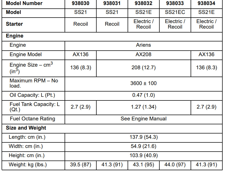
SPECIFICATIONS