PLUG-IN RECEIVER
Functional Range ����������������������������������������������������������������������������������������������������������������������up to 150ft
Maximum Tungsten Load ����������������������������������������������������������������������������������������������������������������300W
Maximum Resistive Load �����������������������������������������������������������������������������������������������������������������300W
Rating ������������������������������������������������������������������������������������������������������������������������������� 2�5A / 120V / 60Hz
Maximum CFL/LED Load �������������������������������������������������������������������������������������������������������������������100W
Works with dimmable LED, CFL and incandescent bulbs.
REMOTE TRANSMITTER
Functional Range ����������������������������������������������������������������������������������������������������������������������up to 150ft
Battery Type �����������������������������������������������������������������������������������������������������������������������������������������CR2032
* Functional range may be adversely affected by one or more of the
following factors: weather, radio frequency interference, low transmitter
battery and obstructions between the transmitter and receiver.
FCC STATEMENT
This device complies with Part 15 of the FCC and Industry Canada license-exempt
RSS standard(s)� Operation is subject to the following two conditions: (1 this device
may not cause harmful interference, and (2) this device must accept any interference
received, including interference that may cause undesired operation�
FCC NOTE: The manufacturer is not responsible for any radio or TV interference caused by
unauthorized modifications to this equipment� Such modifications could void the user’s
authority to operate the equipment� NOTE: This equipment has been tested and found to
comply with the limits for a Class B digital device, pursuant to Part 15 of the FCC Rules�
These limits are designed to provide reasonable protection against harmful interference in
a residential installation� This equipment generates, uses and can radiate radio frequency
energy and, if not installed and used in accordance with the instructions may cause harmful
interference to radio communications� However, there is no guarantee that interference will not
occur in a particular installation� If this equipment does cause harmful interference to radio or
television reception, which can be determined by turning the equipment off and on, the user
is encouraged to try to correct the interference by one or more of the following measures:
• Reorient or relocate the receiving antenna�
• Increase the separation between the equipment and receiver�
• Connect the equipment into an outlet on a circuit different
from that to which the receiver is connected�
• Consult the dealer or an experienced radio/TV technician for help�
CAN ICES-3(B)/NMB-3(B) | FCC: Q2I1618278 | IC 6924A-JP830171L8
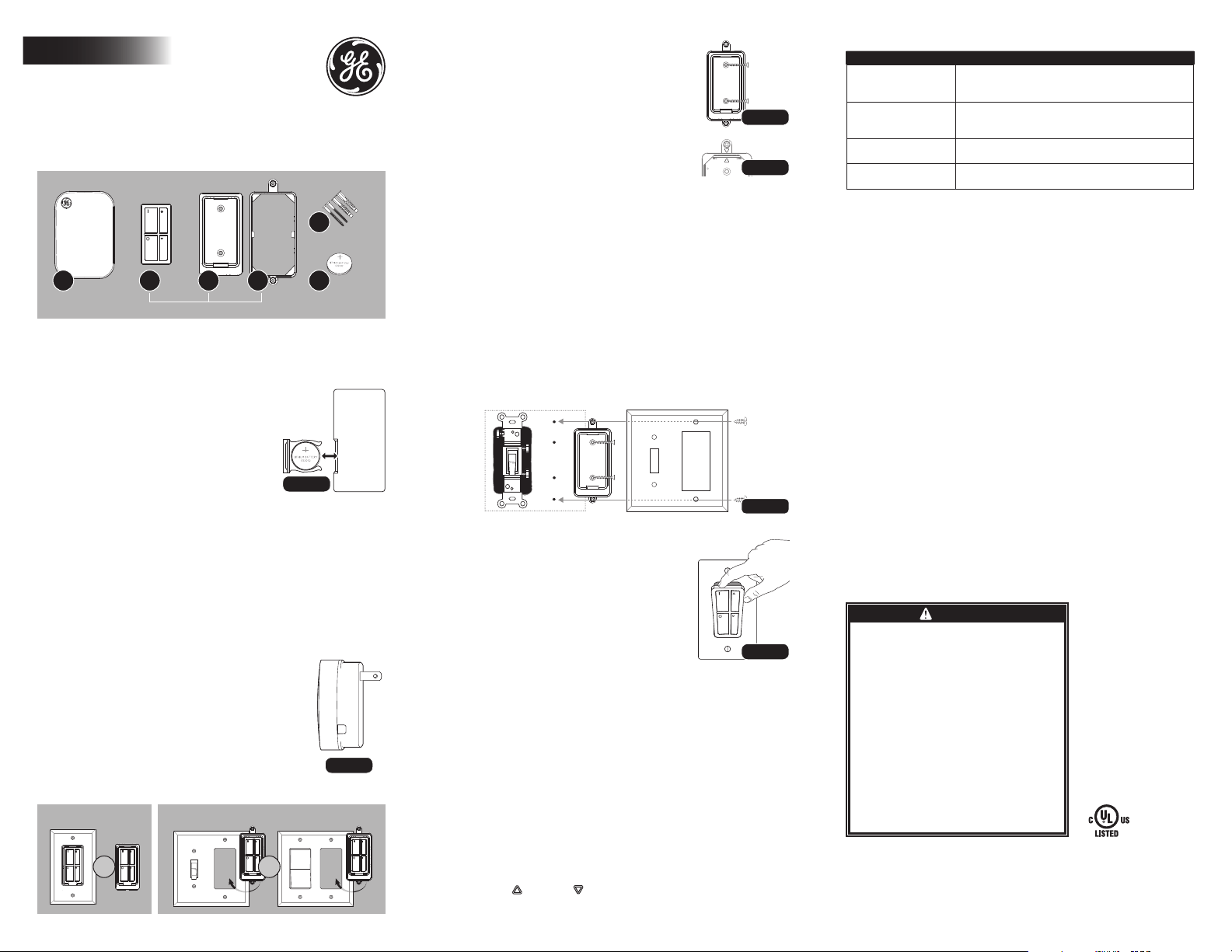
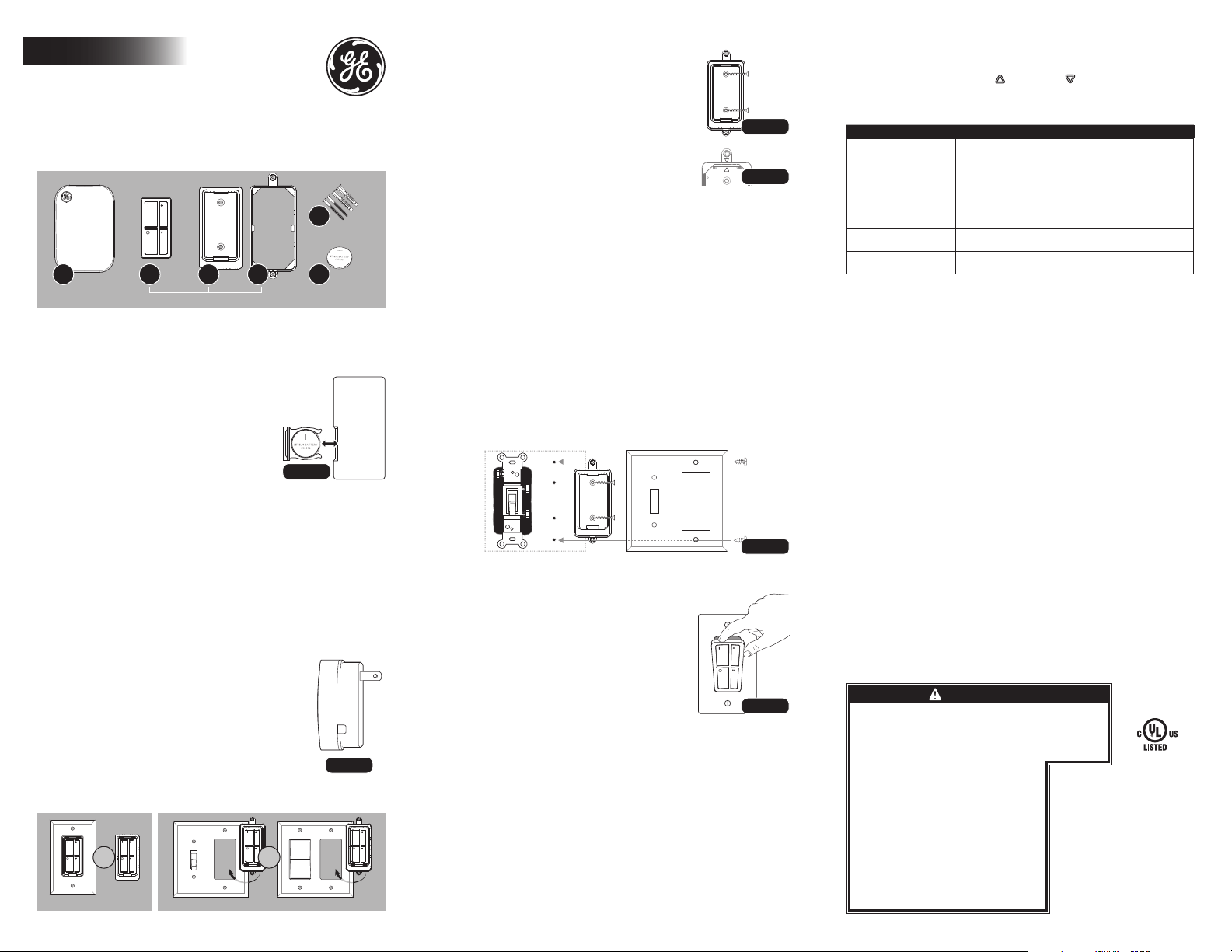
INSTALLING BATTERY (REMOTE) [FIG.1]
1� Find the remote and CR2032 battery
(included in package)�
2� Remove transmitter from the remote wall
mount — push down and out from the top of
the remote (“I” button is on top) [FIG.6]�
3� Turn remote over and pull out
battery drawer [FIG.1]�
4� Place battery in the drawer with (+)
side of the battery facing up�
5� Push the battery drawer back into remote�
(Red indicator light on the front of remote should light up when a button is pushed.)
INSTALLATION INSTRUCTIONS (DIMMING RECEIVER)
1� Plug lamp or the device to be controlled into the outlet on the side of
the receiver� Make sure lamp or device is turned to the ON position�
2� Plug the receiver into a standard indoor outlet�
3� Wait 5 seconds for the receiver to activate�
IMPORTANT: It will take 5 seconds from the time the receiver is
plugged into the outlet before the remote will be functional.
DIMMING RANGE
SETTING
1� Press the down arrow on the dimmer remote
until the light is at the lowest desired level�
2� Once the light reaches the desired level, press and
hold the button on the side of the receiver [FIG.2]� for 3
seconds to set the bottom of the dimming range�
3� Light will now dim and brighten within the desired range�
RESETTING
1� To reset the desired dim level, simply press and hold the
button on the side of the receiver for 5 seconds [FIG.2]�
MOUNTING REMOTE OPTIONS
OPTION 1: WALL MOUNT WITH OR WITHOUT WALLPLATE
1� Place remote mount with wallplate bracket
where mounting, and mark the remote mount
holes on the wall [FIG.3]� Arrows on the back
of remote mount indicate the top [FIG.4]�
2� If mounting directly to a stud, drill holes using
a 3/32” drill bit (anchors will not be used)�
3� If mounting to drywall, drill holes using a
1/4” drill bit� Gently tap in anchors�
4� Remove wallplate bracket if mounting
without a wallplate�* Leave the wallplate
bracket on if using a wallplate�
*To separate the remote mount from the wallplate bracket, hold the wallplate
bracket by the wallplate holes. Turn the wallplate bracket so you are looking at
the arrows [FIG.4]. Gently push the remote out of the wallplate bracket.
5� Screw in remote mount using mounting screws� Do not overtighten�
6� Screw on wallplate (not included)�
7� Proceed to INSERTING AND REMOVING REMOTE�
NOTE: If reassembling the wallplate bracket with the remote mount, verify the that
the arrows line up on the back of the remote mount and wallplate bracket [FIG 4].
OPTION 2: WALL MOUNT WITH EXISTING WIRED SWITCH
1� Screw the remote mount with wallplate bracket onto the
wallplate that will be used (not included)� This will now be
the wallplate bracket assembly (B2, B3 & wallplate)�
2� Place the wallplate bracket assembly on the existing
switch box and mark the remote mount holes�
3� If mounting directly to a stud, drill holes using a
3/32” drill bit (anchors will not be used)�
4� If mounting to drywall, drill holes using a 1/4” drill bit� Gently tap in anchors�
5� Place wallplate bracket assembly (B2, B3 & wallplate) into place, and screw
in the wallplate to the existing switch, as well as screwing the wall mount�
INSERTING AND REMOVING REMOTE
FROM WALL MOUNT
INSERTING
1� Place bottom of remote over the spring tab
in the remote bracket, gently press down and
push into the remote bracket� [FIG. 6]
2� Remote should snap in and be held firmly in place�
REMOVING
1� Gently push the top of the remote down and
out from the remote mount� [FIG. 6]
NOTE: May not work with screwless wallplates.
PAIRING AND UNPAIRING RECEIVER
(LIGHTING CONTROL COMES PAIRED IN THE PACKAGE� THIS SHOULD
ONLY BE NEEDED IF ADDING REMOTES AND/OR RECEIVERS OR
IF YOUR LIGHTING CONTROL HAS BECOME UNPAIRED)
PAIRING — LINKING REMOTE TO RECEIVER
1� Make sure the receiver is not plugged into the outlet
and the remote is close with battery installed�
2� Plug receiver into the outlet�
3� Within the first 5 seconds after plugging in, press and
hold any button on the remote for 2 seconds�
4� After 5 seconds from plugging the receiver into the
outlet, the remote and receiver will be paired�
UNPAIRING — REMOVING ALL PAIRED DEVICES FROM RECEIVER
1� Hold down the ON and the OFF buttons at the same time for 5 seconds�
2� Receiver will delete ALL transmitters programmed in it�
REMOTE FUNCTIONALITY
1� Use “I” and “O” buttons to turn the light ON/OFF�
2� Use the up (
) and down ( ) buttons to find desired dimming level�
Wireless Remote with Dimming
Lighting Control Manual
Indoor
A B1 B2 B3
C
D
FIG.6
FIG. 1
37781 V1
04/05/17 RT
FIG.5
TROUBLESHOOTING
Problem Corrective Action
Indicator light on remote
does not light up red
when button is pushed
• Battery may be installed incorrectly� Reinstall battery�
• Battery may need to be replaced�
Install new CR2032 battery�
Indicator light on
remote lights up and
light does not turn on
• Make sure light is turned on and light bulb is working
• Receiver may have become un-paired� Pair remote
to receiver — see pairing section of manual�
Wallplate does not fit on
wall mount correctly
• Verify that the arrows on the back of the wallplate
bracket and the remote mount line up�
Wallplate screws are too
long and hit the wall
• Use ¼” drill bit and drill indentations into
drywall where the screws touch the wall�
ENCLOSED YOU WILL FIND:
A� Plug-in receiver
B1� Remote transmitter
B2� Remote wall mount
B3� Wallplate bracket
C� Mounting screws and anchors
D� CR2032 battery
assembled in package
FIG. 3
FIG. 4
OPTION 1 OPTION 2
OR OR
MADE IN CHINA
GE is a trademark of General Electric Company and is under license by
Jasco Products Company LLC, 10 E� Memorial Rd�, Oklahoma City, OK 73114�
This Jasco product comes with a 1-year limited warranty�
Visit www�byjasco�com for warranty details�
Questions? Contact us at 1-800-654-8483 between 7:00AM—8:00PM CST�
FIG. 2
CAUTION: TO REDUCE THE RISK OF OVERHEATING AND
POSSIBLE DAMAGE TO OTHER EQUIPMENT, DO NOT
INSTALL TO CONTROL A MOTOR-OPERATED APPLIANCE, A
FLUORESCENT LIGHTING FIXTURE, OR A TRANSFORMER
SUPPLIED APPLIANCE�
BATTERY MAY LEAK HARMFUL LIQUIDS OR IGNITABLE
MATERIALS OR EXPLODE CAUSING INJURY OR PRODUCT
DAMAGE�
• REPLACE FULLY DISCHARGED BATTERY IMMEDIATELY
• REMOVE BATTERY IF PRODUCT IS TO BE UNUSED FOR
EXTENDED PERIOD OF TIME
RISK OF ELECTRIC SHOCK
• FULLY INSERT PLUG
• KEEP CHILDREN AWAY
• USE INDOORS ONLY
• DO NOT USE IN WET LOCATIONS
• UNPLUG BEFORE CLEANING
RISK OF FIRE
• DO NOT EXCEED ELECTRICAL RATINGS
• DO NOT USE TO CONTROL MOTOR-OPERATED APPLIANCES,
TRANSFORMER-SUPPLIED APPLIANCES OR APPLIANCES
THAT CONTAIN HEATING ELEMENTS (COOKERS, IRONS,
HEATERS, ETC�)
WARNING
INSTALAR LA PILA (CONTROL REMOTO) [FIG. 1]
1� Ubique el control remoto y la pila CR2032
(que se incluyen en el paquete)�
2� Extraiga el transmisor del montaje de pared
del control remoto, empuje hacia abajo y hacia
afuera por la parte superior del control (el botón
“I” se encuentra en la parte superior)
[FIG.6]�
3� Gire el control remoto y extraiga el
compartimento para la pila [FIG.1]�
4� Coloque la pila en el
compartimento con el lado (+) hacia arriba�
5� Vuelva a colocar el compartimento en el control remoto�
(El indicador rojo, que se encuentra en la parte delantera del
control remoto, se ilumina al presionar un botón).
INSTRUCCIONES PARA LA INSTALACIÓN (RECEPTOR DE ATENUACIÓN)
1� Enchufe la lámpara o el dispositivo que desea controlar en el tomacorriente
que se encuentra en la parte lateral del receptor� Asegúrese de que
la lámpara o el dispositivo esté encendido (posición ON)�
2� Enchufe el receptor en un tomacorriente común para interiores�
3� Espere 5 segundos hasta que se active�
IMPORTANTE: Demora unos 5 segundos desde que se enchufa el
receptor hasta que comienza a funcionar el control remoto
RANGO DE ATENUACIÓN
CONFIGURACIÓN
1� Presione la flecha hacia abajo en el atenuador remoto hasta
que la luz llegue al nivel deseado�
2� Una vez que la luz alcance el nivel deseado, presione el
botón del lado del receptor [FIG.2] y manténgalo presionado
durante 3 segundos para ajustar el punto inferior del rango
de atenuación�
3� La luz se atenuará e iluminará dentro del rango deseado�
REINICIO
4� Para restablecer el nivel de atenuación deseado, solo
debe presionar el botón del lado del receptor y mantenerlo
presionado durante 5 segundos [FIG.2]�
OPCIONES DE MONTAJE DEL CONTROL REMOTO
OPCIÓN 1: MONTAJE SOBRE PARED CON O SIN PLACA
1� Coloque el montaje del control remoto con el soporte
de la placa donde realizará la instalación y marque los
orificios en la pared [FIG. 2]� Las flechas en la parte trasera
del montaje indican cuál es la parte superior [FIG.3]�
2� Si la instalación se realiza directamente con un
perno, haga las perforaciones con una broca
tamaño 3/32” (no se utilizarán fijaciones)�
3� Si la instalación se realiza sobre un panel,
haga las perforaciones con una broca tamaño
1/4”� Golpee suavemente las fijaciones�
4� Quite el soporte de la placa, en caso de que no lo
utilice para la instalación�* Mantenga el soporte
de la placa, en caso de que lo vaya a utilizar�
*Para separar el montaje del control remoto del soporte de la placa de pared, sujete el soporte
por las perforaciones. Gire el soporte de la placa de pared, de manera que las flechas queden
frente a usted [FIG. 3]. Empuje suavemente el control remoto para extraerlo del soporte.
5� Ajuste el montaje del control remoto con los tornillos
provistos� No apriete demasiado�
6� Atornille el montaje en la placa de pared (no se incluye)�
7� Vaya a la sección INSERTAR Y EXTRAER EL CONTROL REMOTO�
NOTA:Si está reensamblando el soporte de la placa de pared con el montaje del control remoto,
compruebe que las flechas queden alineadas en la parte trasera del montaje y del soporte [FIG 3].
OPCIÓN 2: MONTAJE DE PARED CON INTERRUPTOR CABLEADO EXISTENTE
1� Atornille el montaje del control remoto con el soporte de la placa de
pared que utilizará (no se incluye)� Este se convertirá en el montaje
del soporte de la placa de pared
(B2, B3 y la placa de pared)�
2� Coloque este montaje en la caja del interruptor existente y
marque los orificios de montaje del control remoto�
3� Si la instalación se realiza directamente con un perno, haga las
perforaciones con una broca tamaño 3/32” (no se utilizarán fijaciones)�
4� Si la instalación se realiza sobre un panel, haga las perforaciones
con una broca tamaño 1/4”� Golpee suavemente las fijaciones�
5� Coloque el montaje de soporte (B2, B3 y la placa de pared))
en su lugar y atornille la placa en el interruptor existente�
Asimismo, atornille el montaje de pared en las fijaciones�
INSERTAR Y EXTRAER EL CONTROL REMOTO DEL MONTAJE DE PARED
INSERTAR
1� Coloque la parte inferior del control remoto
sobre la lengüeta con resorte en el soporte,
empuje suavemente hacia abajo y cálcelo en
el soporte del control remoto� [FIG. 5]
2� El control remoto debe quedar
insertado y firme en su lugar
EXTRAER
1� Empuje suavemente la parte superior del control remoto
hacia abajo y hacia afuera para extraerlo [FIG. 5]
NOTA: Es probable que no funcione con placas de pared sin tornillos.
ACOPLAR Y DESACOPLAR EL RECEPTOR
(EL CONTROL REMOTO DE LUCES YA VIENE ACOPLADO
EN EL PAQUETE� ESTE PROCEDIMIENTO SOLO SERÁ NECESARIO SI AGREGA
CONTROLES O RECEPTORES, O BIEN SI EL CONTROL DE LUCES SE DESACOPLA)�
ACOPLAR: ENLAZAR EL CONTROL REMOTO CON EL RECEPTOR
1� Asegúrese de que el receptor no esté enchufado en el tomacorriente y
de que el control remoto esté a su alcance, con la pila instalada�
2� Enchufe el receptor en el tomacorriente�
3� A los 5 segundos de haberlo enchufado, presione
cualquier botón en el control remoto�
4� Al cabo de 5 segundos, el control remoto y el receptor quedarán acoplados�
DESACOPLAR: EXTRAER TODOS LOS DISPOSITIVOS ACOPLADOS DEL RECEPTOR
1� Mantenga presionados los botones ON y OFF al mismo tiempo durante 5 segundos�
FIG. 1
A B1 B2 B3
C
D
ensamblado en el paquete
FIG.6
FIG.5
FIG. 3
FIG. 4
O O
B3� Soporte de la placa de pared
C� Tornillos de montaje y fijaciones
D� Pila CR2032
EN EL PAQUETE ENCONTRARÁ LO SIGUIENTE:
A� Receptor para enchufar
B1� Transmisor remoto
B2� Montaje de pared del control remoto
HECHO EN CHINA
GE es una marca comercial de General
Electric Company con licencia otorgada
a Jasco Products Company LLC,
10 E� Memorial Rd�,
Oklahoma City, OK 73114�
Este producto de Jasco tiene una
garantía limitada de 1 año�
Visite www�byjasco�com para
conocer los detalles de la garantía�
¿Preguntas? Comuníquese al 1-800-
654-8483 entre las 7:00 a� m� y las 8:00
p� m� CST (hora central estándar)�
RECEPTOR PARA ENCHUFAR
Alcance operativo: ������������������������������������������������������������������������������������������hasta 150 pies (45,7 m)
Carga de tungsteno máxima: �������������������������������������������������������������������������������������������������������360 W
Carga resistiva máxima: ���������������������������������������������������������������������������������������������������������������1875 W
Capacidad nominal: ���������������������������������������������������������������������������������������������������15 A/120 V/60 Hz
Carga máxima de CFL/LED: ������������������������������������������������������������������������������������������������������������100W
TRANSMISOR REMOTO
Alcance operativo: ������������������������������������������������������������������������������������������hasta 150 pies (45,7 m)
Tipo de pila: ������������������������������������������������������������������������������������������������������������������������������������������� CR2032
* El rango de funcionamiento podría verse afectado por uno o más de los siguientes factores: clima,
interferencia de frecuencia radial, pila baja del transmisor y bloqueos entre el transmisor y el receptor.
DECLARACIÓN DE LA COMISIÓN FEDERAL DE COMUNICACIONES (FCC)
Este dispositivo cumple con las especificaciones del apartado 15 de las normas de la FCC y con las
especificaciones de las normas radioeléctricas (RSS) del Ministerio de Industria de Canadá aplicables
a aparatos exentos de licencia� El funcionamiento está sujeto a las siguientes dos condiciones:
(1) este dispositivo no debe provocar interferencia perjudicial, y (2) este dispositivo debe aceptar
toda interferencia que reciba, incluso la que pudiera causar un funcionamiento no deseado�
NOTA DE LA FCC: El fabricante no se hace responsable de ninguna interferencia radial o
televisiva ocasionada por modificaciones no autorizadas, efectuadas en este equipo� Estas
modificaciones podrían anular la autoridad del usuario para utilizar este equipo� NOTA: Este
equipo ha sido probado y cumple con los límites establecidos para dispositivos digitales de
Clase B, de conformidad con el apartado 15 de la normativa de la FCC� Estos límites están
diseñados para proveer protección razonable contra interferencias perjudiciales en instalaciones
residenciales� Este equipo genera, utiliza y puede irradiar energía de radiofrecuencia� De no
instalarse y utilizarse según las instrucciones, puede provocar interferencia perjudicial a las
radiocomunicaciones� No obstante, no es posible garantizar que no se producirán interferencias
en una determinada instalación� Si este equipo provoca interferencia perjudicial a la recepción de
radio o televisión, lo que puede determinarse encendiendo y apagando el equipo, se recomienda
al usuario intentar corregir la interferencia a través de una o más de las siguientes medidas:
• Reorientar o reubicar la antena receptora�
• Incrementar la separación entre el equipo y el receptor�
• Conectar el equipo a un tomacorriente de un circuito diferente
del circuito al que está conectado el receptor�
• Consultar al distribuidor o a un técnico con experiencia en radio/televisión para solicitar asistencia�
CAN ICES-3(B)/NMB-3(B) | FCC: Q2I1618278 | IC 6924A-JP830171L8
RESOLUCIÓN DE PROBLEMAS
Problema Acción correctiva
La luz del indicador del
control remoto no se vuelve
roja al presionar el botón�
• Es posible que la pila no esté correctamente
instalada� Vuelva a instalarla�
• Es posible que sea necesario reemplazar la
pila� Coloque una pila CR2032 nueva�
La luz del indicador del
control remoto se enciende,
pero la luz no se prende�
• Compruebe que la luz esté encendida y que la bombilla funcione�
• Es posible que el receptor se haya desacoplado�
Acople el control remoto con el receptor� Consulte
la sección de acoplamiento del manual�
La placa de pared no calza
correctamente en el montaje�
• Compruebe que las flechas en la parte posterior del soporte de
pared y que el montaje del control remoto estén alineados�
Los tornillos de la placa son
muy largos y tocan la pared�
• Con una broca de ¼”, realice perforaciones en el
panel donde los tornillos tocan la pared�
2� El receptor borrará TODOS los transmisores que tenga programados�
FUNCIONALIDAD REMOTA
1� Utilice los botones “I” y “O” para encender o apagar la luz�
2� Utilice los botones hacia arriba ( ) y hacia abajo ( ) hasta alcanzar el nivel de
atenuación deseado�
FIG. 2
Manual del
control remoto de luces
inalámbrico con cuenta regresiva
Para interiores
OPCIÓN 1 OPCIÓN 2
ADVERTENCIA
PRECAUCIÓN: A FIN DE DISMINUIR EL RIESGO DE RECALENTAMIENTO Y DE
POSIBLES DAÑOS EN LOS DEMÁS EQUIPOS, NO INSTALAR PARA CONTROLAR
LOS APARATOS QUE FUNCIONAN A MOTOR, ARTEFACTOS DE ILUMINACIÓN DE
LUZ FLUORESCENTE O APARATOS ALIMENTADOS CON TRANSFORMADORES�
LA PILA PUEDE PERDER LÍQUIDOS NOCIVOS O MATERIALES INFLAMABLES, O
BIEN EXPLOTAR Y CAUSAR LESIONES O DAÑAR LOS PRODUCTOS�
• REEMPLACE LA PILA COMPLETAMENTE DESCARGADA
DE INMEDIATO�
• QUITE LA PILA SI NO USARÁ EL PRODUCTO DURANTE UN
PERÍODO PROLONGADO
RIESGO DE DESCARGA ELÉCTRICA
• ENCHUFE COMPLETAMENTE LA CLAVIJA
• MANTENGA FUERA DEL ALCANCE DE LOS NIÑOS
• SOLO PARA USO EN INTERIORES
• NO UTILICE EN LUGARES HÚMEDOS
• DESCONECTE ANTES DE LIMPIAR
RIESGO DE INCENDIO
• NO SUPERE LOS VALORES NOMINALES ELÉCTRICOS
• NO UTILICE ESTE EQUIPO PARA CONTROLAR
DISPOSITIVOS QUE FUNCIONAN A MOTOR,
ALIMENTADOS CON TRANSFORMADOR O QUE INCLUYAN
RESISTENCIA ELÉCTRICA (COCINAS, PLANCHAS,
CALEFACTORES, ETC�)