Loading ...
Loading ...
Loading ...
Wine Column Refrigeration Installation & Operation Manual
Printed in USA 4
PRIOR TO INSTALLATION
Safety Precautions
W ARNING
Inspect the electrical cord
and plug for damage prior
to plugging the unit in.
CAUTION
If service is necessary,
repair work must be
performed by a Perlick authorized servicer.
Work done by unqualied individuals could
potentially be dangerous and will void the
warranty.
CAUTION
If unit has been laid on its
back or sides, place unit
upright and allow minimum of 24 hours before
connecting power. Failure to follow this
procedure may damage the compressor and
void the warranty.
DANGER
Do not use or store
flammable liquids (ie;
gasoline) or vapors near the appliance.
DANGER
Perlick columns are top
heavy. It is important that it
is secured at all times with the door closed
until installed. Install as directed using anti-tip
brackets provided to prevent tipping.
DANGER
Take special care when
moving to prevent injury.
Electrical
DANGER
Serious electrocution
hazard. Electrical
grounding is required. This appliance is
equipped with a 3-prong (grounding) polarized
plug for your protection against possible
shock hazards. Failure to comply with these
electrical guidelines may result in possible
death or serious injury, re or loss of property.
W ARNING
Never use an extension
cord to connect the unit to
the electrical source. Do not use a two-prong
adapter or remove the power cord ground
prong.
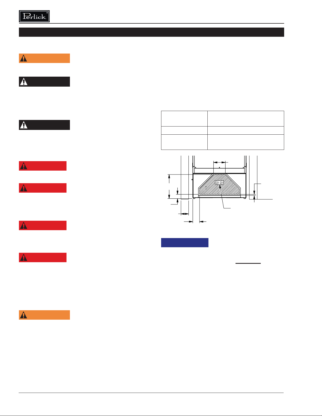
Installation must comply with all applicable
electrical codes. The electrical supply must be
located within the shaded area of the illustration
below. A separate circuit, servicing only this
appliance, is required. A ground fault circuit
interrupter (GFCI) is not recommended and may
cause interruption of operation. The outlet should
be placed in the hatched area dimensioned below.
Electrical Supply 115V, 60Hz., Phase 1, 3.3
amps
Service Dedicated 15 amp circuit
Power/Cord Type/
Length
NEMA 5-15P w/5’ power cord
84"
4"
24"
83 11/16"
14 1/8"
66 1/2"
4"
OVERLAY TEMPLATE
DIMENSIONAL LIMIT
21.5/8"
1 4/5"
13 3/8"
22 3/16"
24 1/16"
23 3/4"
28"
90°
50 1/8"
1/2"
3"
3"
10 3/4"
5 1/4"
ELECTRICAL
OUTLET
LOCATION
CABINET
OPENING
N OTICE
This product contains
blown foam insulation
using blowing agent R-611 (Methyl Formate).
The foam in this product does not contain
HFC’s, CFC’s, or HCFC’s.
Loading ...
Loading ...
Loading ...