Write the model and serial
numbers here:
Model # __________________
Serial # ___________________
You can find them on a label on
the side trim or on the front of the
(lower) oven behind the oven door.
Printed in the United States
PCB980 - 76.2 cm (30") Free-Standing Double Oven
Owner’s Manual
Safety Information .............2
Warranty ........................7
Assistance / Accessories ......8
Using The Range
Surface Units ......................9
Cookware for Radiant
Glass Cooktop ...................12
Double Oven Controls .............13
Special Features ..................14
Sabbath Mode ....................15
Oven Racks .......................16
Aluminum Foil and Oven Liners ....17
Cookware .........................17
Cooking Modes ...................18
Cooking Guide ....................19
Care and Cleaning
Cleaning the Range – Exterior .....21
Cleaning the Range – Interior ......22
Cleaning the Glass Cooktop ........23
Maintenance ......................25
Troubleshooting Tips .........30
Ranges
Electric Free-Standing
49-80773 08-15 GE
2
49-80773
Read all safety instructions before using the product. Failure to follow these instructions may result in fire,
electrical shock, serious injury or death.
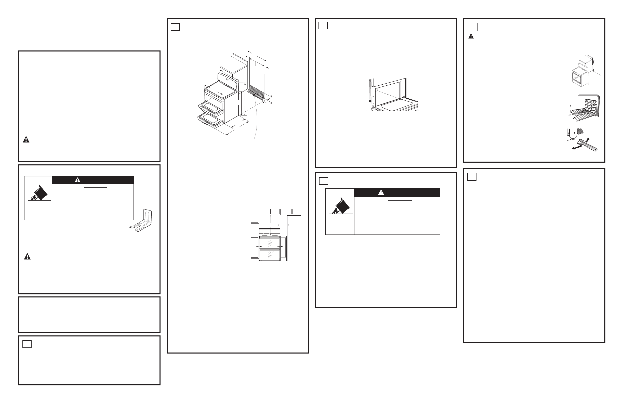
ANTI-TIP DEVICE
WARNING
IMPORTANT SAFETY INFORMATION
READ ALL INSTRUCTIONS BEFORE USING
SAFETY INFORMATION
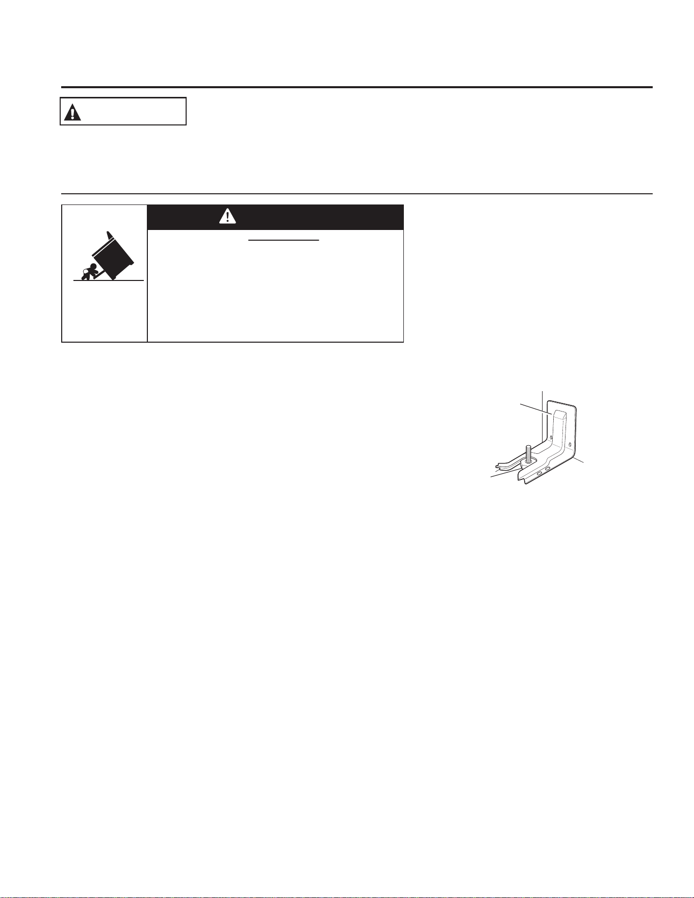
To reduce the risk of tipping the range,
the range must be secured by a properly
installed anti-tip bracket. See installation
instructions shipped with the bracket for
complete details before attempting to install.
For Free-Standing and Slide-In Ranges
To check if the bracket is installed and
engaged properly, look underneath the
range to see that the rear leveling leg
is engaged in the bracket. On some models, the storage
drawer or kick panel can be removed for easy inspection.
If visual inspection is not possible, slide the range forward,
confirm the anti-tip bracket is securely attached to the floor
or wall, and slide the range back so the rear leveling leg is
under the anti-tip bracket.
If the range is pulled from the wall for any reason, always
repeat this procedure to verify the range is properly secured
by the anti-tip bracket.
Never completely remove the leveling legs or the range will
not be secured to the anti-tip device properly.
If you did not receive an anti-tip bracket with your purchase,
call 1.800.561.3344. For installation instructions of the
bracket, visit: www.GEAppliances.ca.
A child or adult can tip the range and be killed.
Verify the anti-tip bracket has been properly installed
and engaged.
Ensure the anti-tip bracket is re-engaged when the range
is moved.
Do not operate the range without the anti-tip bracket in
place and engaged.
Failure to follow these instructions can result in death or
serious burns to children or adults.
Tip-Over Hazard
WARNING
Anti-Tip
Bracket
Leveling Leg
Free-Standing and Slide-In Ranges
READ AND SAVE THESE INSTRUCTIONS
49-80773
3
SAFETY INFORMATION
Ŷ Use this appliance only for its intended purpose
as described in this Owner’s Manual.
Ŷ Be sure your appliance is properly installed and
grounded by a qualified installer in accordance
with the provided installation instructions.
Ŷ Do not attempt to repair or replace any part of
your range unless it is specifically recommended
in this manual. All other servicing should be
transferred to a qualified technician.
Ŷ Before performing any service, unplug the range
or disconnect the power supply at the household
distribution panel by removing the fuse or
switching off the circuit breaker.
Ŷ Do not leave children alone—children should
not be left alone or unattended in an area where
an appliance is in use. They should never be
allowed to climb, sit or stand on any part of the
appliance.
Ŷ CAUTION: Do not store items of
interest to children above a range or on the
backguard of a range—children climbing on the
range to reach items could be seriously injured.
Ŷ Use only dry pot holders—moist or damp pot
holders on hot surfaces may result in burns from
steam. Do not let pot holders touch hot surface
units or heating elements. Do not use a towel or
other bulky cloth in place of pot holders.
Ŷ Never use your appliance for warming or heating
the room.
Ŷ Do not touch the surface units, the heating
elements or the interior surface of the oven.
These surfaces may be hot enough to burn
even though they are dark in color. During and
after use, do not touch, or let clothing or other
flammable materials contact the surface units,
areas nearby the surface units or any interior
area of the oven; allow sufficient time for cooling
first. Other surfaces of the appliance may
become hot enough to cause burns. Potentially
hot surfaces include the cooktop, areas facing
the cooktop, oven vent opening, surfaces near
the opening and crevices around the oven door.
Ŷ Do not heat unopened food containers. Pressure
could build up and the container could burst,
causing an injury.
Ŷ 'RQRWXVHDQ\W\SHRIIRLORUOLQHUWRFRYHUWKHRYHQ
bottom or anywhere in the oven, except as described
in this manual. Oven liners can trap heat or melt,
resulting in damage to the product and risk of shock,
smoke or fire.
Ŷ Avoid scratching or impacting glass doors, cook
tops or control panels. Doing so may lead to
glass breakage. Do not cook on a product with
broken glass. Shock, fire or cuts may occur.
Ŷ Cook meat and poultry thoroughly—meat to at
least an internal temperature of 71.1°C (160°F)
and poultry to at least an internal temperature of
82.2°C (180°F). Cooking to these temperatures
usually protects against foodborne illness.
GENERAL SAFETY INSTRUCTIONS
WARNING
Ŷ Do not store or use flammable materials in
an oven or near the cooktop, including paper,
plastic, pot holders, linens, wall coverings,
curtains, drapes and gasoline or other flammable
vapors and liquids.
Ŷ
Never wear loose-fitting or hanging garments while
using the appliance. These garments may ignite if
they contact hot surfaces causing severe burns.
Ŷ Do not let cooking grease or other flammable
materials accumulate in or near the range.
Grease in the oven or on the cooktop may ignite.
Ŷ Clean ventilating hoods frequently. Grease
should not be allowed to accumulate on the hood
or filter.
KEEP FLAMMABLE MATERIALS AWAY FROM THE RANGE
Failure to do so may result in fire or personal injury.
WARNING
READ AND SAVE THESE INSTRUCTIONS
4
49-80773
IMPORTANT SAFETY INFORMATION
READ ALL INSTRUCTIONS BEFORE USING
SAFETY INFORMATION
Ŷ Do not use water on grease fires. Never pick up
a flaming pan. Turn the controls off. Smother a
flaming pan on a surface unit by covering the
pan completely with a well-fitting lid, cookie sheet
or flat tray. Use a multi-purpose dry chemical or
foam-type fire extinguisher.
Ŷ If there is a fire in the oven during baking,
smother the fire by closing the oven door and
turning the oven off or by using a multi-purpose
dry chemical or foam-type fire extinguisher.
Ŷ If there is a fire in the oven during self-clean, turn
the oven off and wait for the fire to go out. Do
not force the door open. Introduction of fresh air
at self-clean temperatures may lead to a burst
of flame from the oven. Failure to follow this
instruction may result in severe burns.
IN THE EVENT OF A FIRE, TAKE THE FOLLOWING
STEPS TO PREVENT INJURY AND FIRE SPREADING
WARNING
Ŷ
Never leave the surface units unattended at
medium or high heat settings. Boilovers cause
smoking and greasy spillovers that may catch
on fire.
Ŷ Never leave oil unattended while frying. If allowed
to heat beyond its smoking point, oil may ignite
resulting in fire that may spread to surrounding
cabinets. Use a deep fat thermometer whenever
possible to monitor oil temperature.
Ŷ
To avoid oil spillover and fire, use a minimum
amount of oil when shallow pan-frying and
avoid cooking frozen foods with excessive
amounts of ice.
Ŷ Use proper pan size—select cookware having
flat bottoms large enough to cover the surface
heating element. The use of undersized
cookware will expose a portion of the surface
unit to direct contact and may result in ignition
of clothing. Proper relationship of cookware to
surface unit will also improve efficiency.
Ŷ Only certain types of glass, glass/ceramic,
earthenware or other glazed containers are
suitable for cooktop service; others may break
because of the sudden change in temperature.
Ŷ To minimize the possibility of burns, ignition of
flammable materials and spillage, the handle of a
container should be turned toward the center of
the range without extending over nearby surface
units.
Ŷ When preparing flaming foods under a hood, turn
the fan on.
Ŷ If power is lost to an electric cooktop while a
surface unit is ON, the surface unit will turn back
on as soon as power is restored. In the event of
power loss, failure to turn all surface unit knobs
to the OFF position may result in ignition of items
on or near the cooktop, leading to serious injury
or death.
COOKTOP SAFETY INSTRUCTIONS
WARNING
READ AND SAVE THESE INSTRUCTIONS
49-80773
5
Ŷ Stand away from the range when opening the
oven door. Hot air or steam which escapes can
cause burns to hands, face and/or eyes.
Ŷ Do not use the oven if a heating element
develops a glowing spot during use or shows
other signs of damage. A glowing spot indicates
the heating element may fail and present a
potential burn, fire, or shock hazard. Turn the
oven off immediately and have the heating
element replaced by a qualified service
technician.
Ŷ Keep the oven vent unobstructed.
Ŷ Keep the oven free from grease buildup. Grease
in the oven may ignite.
Ŷ Place oven racks in desired location while oven
is cool. If rack must be moved while oven is hot,
do not let pot holder contact hot heating element
in oven.
Ŷ When using cooking or roasting bags in the
oven, follow the manufacturer’s directions.
Ŷ Pull the oven rack to the stop-lock position when
loading and unloading food from the oven. This
helps prevent burns from touching hot surfaces
of the door and oven walls.
Ŷ Do not leave items such as paper, cooking
utensils or food in the oven when not in use.
Items stored in an oven can ignite.
Ŷ 1HYHUSODFHFRRNLQJXWHQVLOVSL]]DRUEDNLQJVWRQHV
or any type of foil or liner on the oven floor. These
items can trap heat or melt, resulting in damage to the
product and risk of shock, smoke or fire.
OVEN SAFETY INSTRUCTIONS
WARNING
SAFETY INFORMATION
Ŷ Use care when touching the cooktop. The glass
surface of the cooktop will retain heat after the
controls have been turned off.
Ŷ Do not cook on a broken cooktop. If glass
cooktop should break, cleaning solutions and
spillovers may penetrate the broken cooktop and
create a risk of electric shock. Contact a qualified
technician immediately.
Ŷ Avoid scratching the glass cooktop. The cooktop
can be scratched with items such as knives,
sharp instruments, rings or other jewelry, and
rivets on clothing.
Ŷ Do not place or store items that can melt or catch
fire on the glass cooktop, even when it is not
being used. If the cooktop is inadvertently turned
on, they may ignite. Heat from the cooktop or
oven vent after it is turned off may cause them to
ignite also.
Ŷ Use CERAMA BRYTE
®
ceramic Cooktop Cleaner
and CERAMA BRYTE
®
Cleaning Pad to clean
the cooktop. Wait until the cooktop cools and
the indicator light goes out before cleaning. A
wet sponge or cloth on a hot surface can cause
steam burns. Some cleaners can produce
noxious fumes if applied to a hot surface.
NOTE: Sugar spills are an exception. They
should be scraped off while still hot using an
oven mitt and a scraper. See the Cleaning the
glass cooktop section for detailed instructions.
Ŷ Read and follow all instructions and warnings on
the cleaning cream label.
RADIANT COOKTOP SAFETY INSTRUCTIONS
WARNING
READ AND SAVE THESE INSTRUCTIONS

6
49-80773
IMPORTANT SAFETY INFORMATION
READ ALL INSTRUCTIONS BEFORE USING
SAFETY INFORMATION
The self-cleaning feature operates the oven at temperatures high enough to burn away food soils in the
oven. Follow these instructions for safe operation.
Ŷ 'RQRWWRXFKRYHQVXUIDFHVGXULQJVHOIFOHDQ
operation. Keep children away from the oven
during self-cleaning. Failure to follow these
instructions may cause burns.
Ŷ
Before operating the self-clean cycle, remove pans,
shiny metal oven racks and other utensils from the
oven. Only gray porcelain-coated oven racks may
be left in the oven. Do not use self-clean to clean
other parts, such as drip pans or bowls.
Ŷ %HIRUHRSHUDWLQJWKHVHOIFOHDQF\FOHZLSH
grease and food soils from the oven. Excessive
amount of grease may ignite leading to smoke
damage to your home.
Ŷ ,IWKHVHOIFOHDQLQJPRGHPDOIXQFWLRQVWXUQWKH
oven off and disconnect the power supply. Have
it serviced by a qualified technician.
Ŷ 'RQRWFOHDQWKHGRRUJDVNHW7KHGRRUJDVNHWLV
essential for a good seal. Care should be taken
not to rub, damage or move the gasket.
Ŷ 'RQRWXVHRYHQFOHDQHUV1RFRPPHUFLDORYHQ
cleaner or oven liner protective coating of any kind
should be used in or around any part of the oven.
SELF-CLEANING OVEN SAFETY INSTRUCTIONS
WARNING
This device complies with Industry Canada license exempt RSS standard(s). Operation is subject to the
following two conditions:
1. this device may not cause interference, and
2. this device must accept any interference, including interference that may cause undesired operation of
the device.
This device meets the FCC and IC requirements for RF exposure in public or uncontrolled environments.
The antenna(s) used for this transmitter must be installed to provide a separation distance of at least 20
cm from all persons.
READ AND SAVE THESE INSTRUCTIONS

49-80773
7
Staple your receipt here. Proof of the original purchase
date is needed to obtain service under the warranty.
WARRANTY
Thank You! ... for your purchase of a GE Brand appliance.
GE Electric Range Warranty
GEAppliances.ca
All warranty service is provided by our Factory Service Centers, or an authorized Customer Care® technician. To schedule
service on-line, visit us at www.GEAppliances.ca or call 1.800.561.3344. Please have serial number and model number
available when calling for service.
Servicing your appliance may require the use of the onboard data port for diagnostics. This gives a service technician the
ability to quickly diagnose any issues with your appliance and helps Mabe improve its products by providing Mabe with
information on your appliance. If you do not want your appliance data to be sent to Mabe, please advise your technician not
to submit the data to Mabe at the time of service.
For the period of one year from the date of the original purchase, any part of the range which fails due to a defect in
materials or workmanship. During this limited one-year warranty, Mabe will also provide, free of charge, all labor and in-
home service to replace the defective part.
What Mabe will not cover:
Ŷ Service trips to your home to teach you how to use the
product.
Ŷ Improper installation, delivery or maintenance.
Ŷ Failure of the product if it is abused, misused, modified
or used for other than the intended purpose or used
commercially.
Ŷ Damage to the glass cooktop caused by use of cleaners
other than the recommended cleaning creams and
pads.
Ŷ Damage to the glass cooktop caused by hardened
spills of sugary materials or melted plastic that are
not cleaned according to the directions in the Owner's
Manual.
Ŷ Replacement of house fuses or resetting of circuit
breakers.
Ŷ Damage to the product caused by accident, fire, floods
or acts of God.
Ŷ Incidental or consequential damage caused by possible
defects with this appliance.
Ŷ Damage caused after delivery.
Ŷ Product not accessible to provide required service.
Ŷ Service to repair or replace light bulbs, except for LED
lamps.
EXCLUSION OF IMPLIED WARRANTIES
Your sole and exclusive remedy is product repair as provided in this Limited Warranty. Any implied warranties, including
the implied warranties of merchantability or fitness for a particular purpose, are limited to one year or the shortest period
allowed by law.
This warranty is extended to the original purchaser and any succeeding owner for products purchased in Canada for home
use within the Canada. In-home warranty service will be provided in areas where it is available and deemed reasonable by
Mabe to provide.
Some provinces do not allow the exclusion or limitation of incidental or consequential damages. This warranty gives you
specific legal rights, and you may also have other rights which vary from province to province. To know what your legal
rights are in your province consult your local or provincial consumer affairs office.
Warrantor: Mabe Canada Inc., Burlington, Ontario
Register Your Appliance: Register your new appliance on-line at your convenience!
www.geappliances.ca/register/index.jsp
Timely product registration will allow for enhanced communication and prompt service under the terms of your warranty,
should the need arise. You may also mail in the pre-printed registration card included in the packing material.

8
49-80773
ASSISTANCE / ACCESSORIES
Schedule Service: Expert GE repair service is only one
step away from your door. Get on-line and schedule your
service at www.GEAppliances.ca or call 1.800.561.3344
during normal business hours.
Parts and Accessories: Individuals qualified to service
their own appliances can have parts or accessories sent
directly to their homes (VISA, MasterCard and Discover
cards are accepted).Order on-line today, 24 hours
every day or by phone at 800.661.1616 during normal
business hours.
Instructions contained in this manual cover procedures
to be performed by any user. Other servicing generally
should be referred to qualified service personnel. Caution
must be exercised, since improper servicing may cause
unsafe operation.
Contact Us: If you are not satisfied with the service you
receive from GE, contact us on our Website with all the
details including your phone number, or write to:
Director, Customer Relation, Mabe Canada Inc.
Suite 310, 1 Factory Lane
Moncton, N.B. E1C9M33
Try the GE Appliances Website (www.geappliances.ca/customer/appservice.jsp) 24 hours a day, any day of the year!
For greater convenience and faster service, you can now download Owner’s Manuals and schedule service on-line.
Accessories
Looking For Something More?
GE offers a variety of accessories to improve your cooking and maintenance experiences!
To place an order visit us online at:
www.GEAppliances.ca
800.661.1616 National Parts Center (Canada)
The following products and more are available:
How to Remove Protective Shipping Film and Packaging Tape
Carefully grasp a corner of the protective shipping film with
your fingers and slowly peel it from the appliance surface. Do
not use any sharp items to remove the film. Remove all of the
film before using the appliance for the first time.
To assure no damage is done to the finish of the product,
the safest way to remove the adhesive from packaging
tape on new appliances is an application of a household
liquid dishwashing detergent. Apply with a soft cloth and
allow to soak.
NOTE: The adhesive must be removed from all parts. It
cannot be removed if it is baked on.
Accessories
Small Broiler Pan - 22.2 cm x 3.2 cm x 34.3 cm (8 ¾” x 1 ¼” x 13 ½“) 222D2097G001 (Canada)
Large* Broiler Pan - 32.4 cm x 3.2 cm x 41.9 cm (12 ¾” x 1 ¼” x 16 ½“) 222D2097G002 (Canada)
Parts
Oven racks Part numbers vary by model
Oven elements Part numbers vary by model
Light bulbs Part numbers vary by model
Cleaning Supplies
CitruShine Stainless Steel Wipes WX10X10007
CERAMA BRYTE
®
Stainless Steel Appliance Cleaner PM10X311
CERAMA BRYTE
®
Cleaning Pads for Ceramic Cooktops WX10X350
CERAMA BRYTE
®
Ceramic Cooktop Cleaner WX10X300
CERAMA BRYTE
®
Ceramic Cooktop Scraper
WX10X0302
Kit (Kit includes cream and cooktop scraper) WB64X5027
*The large broiler pan does not fit in 20”/24” ranges.
Have a question or need assistance with your appliance?
49-80773
9
USING THE RANGE: Surface Units
Surface Units
FIRE HAZARD: Never leave the range unattended with the cooktop on medium or high
settings. Keep flammable items away from the cooktop. Turn off all controls when done
cooking. Failure to follow these instructions can result in fire, serious injury or death.
WARNING
Throughout this manual, features and appearance may vary from your model.
How to Set
Push the knob in and turn in either direction to the
setting you want.
A surface ON indicator light will glow when any surface
unit is on.
For glass cooktop surfaces:
A HOT COOKTOP indicator light will:
Ŷ FRPHRQZKHQWKHXQLWLVKRWWRWKHWRXFK
Ŷ VWD\RQHYHQDIWHUWKHXQLWLVWXUQHGRII
Ŷ VWD\RQXQWLOWKHXQLWLVFRROHGWR
approximately 65.5°C (150°F).
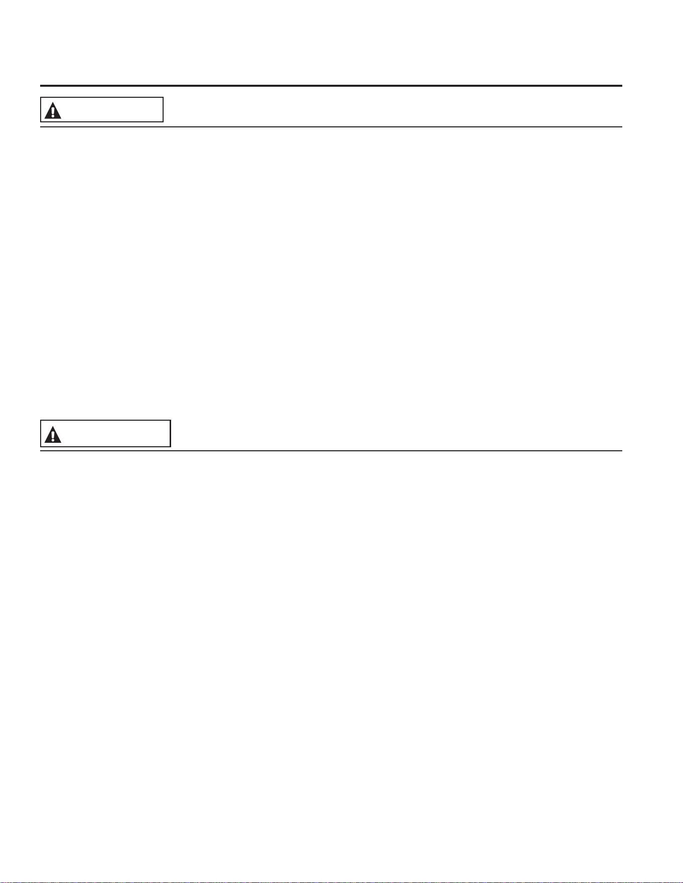
Dual and Triple Surface Units and Control Knobs (on some models)
The surface unit has 2 or 3 cooking sizes to select from so you can match the size of the unit to the size of the
cookware you are using.
At both OFF and HI the control clicks
into position. You may hear slight
clicking sounds during cooking,
indicating the control is maintaining
your desired setting.
Be sure you turn the control knob to
OFF when you finish cooking.
Models with a Dual-Ring surface
element only
Models with a Tri-Ring surface
element only.
Melt setting (on some models) will
melt chocolate or butter.
10
49-80773
Surface Units (Cont.)
USING THE RANGE: Surface Units
Throughout this manual, features and appearance may vary from your model.
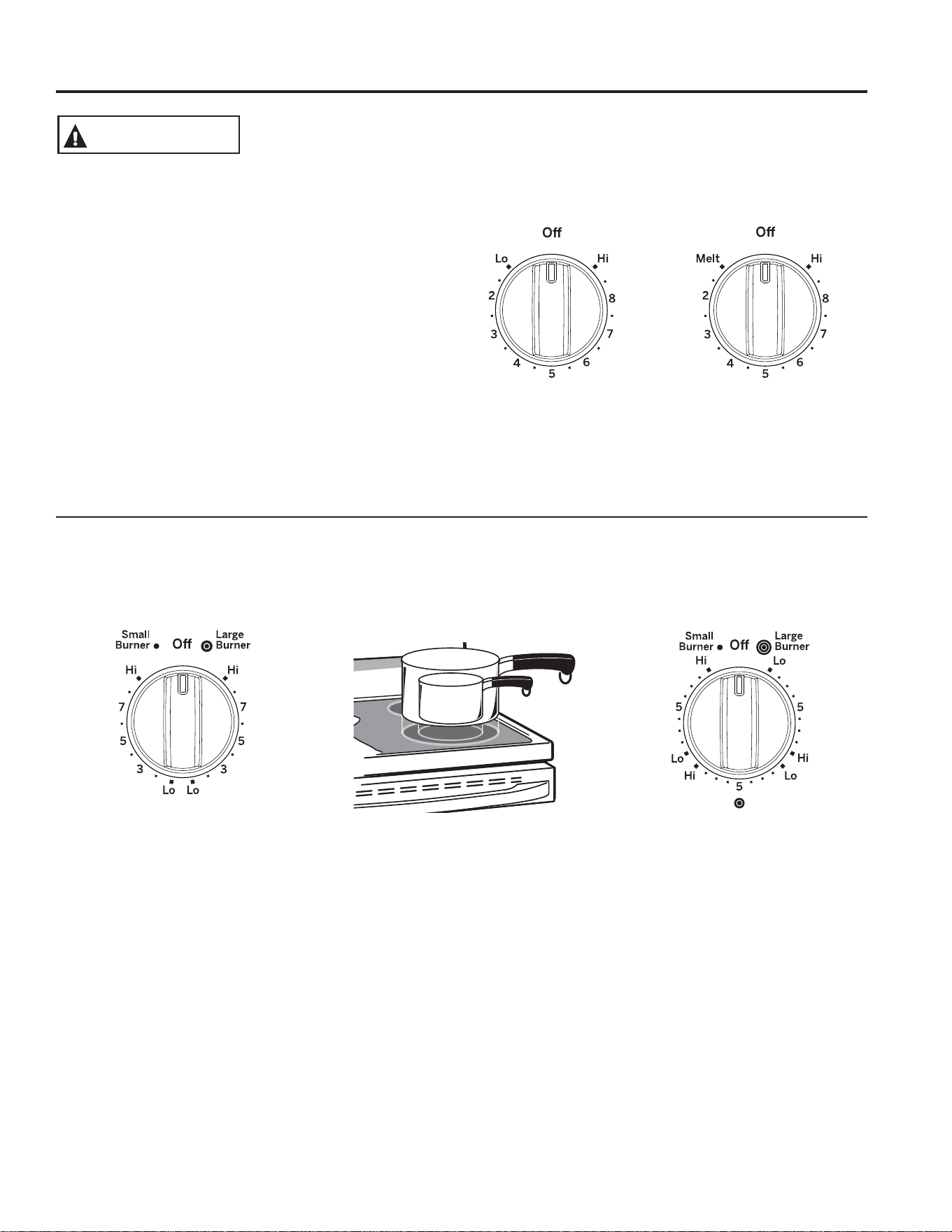
Using the Bridge Zone (on some models)
To use the bridge zone, adjust the knobs for the Left rear
and Left front elements to create one large area for even
cooking.
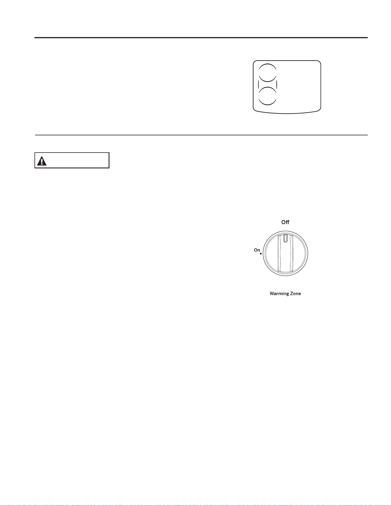
Using the Warming Zone
FOOD POISON HAZARD: Bacteria may grow in food at
temperatures below 60°C (140°F).
Ŷ $OZD\VVWDUWZLWKKRWIRRG'RQRWXVHZDUPVHWWLQJWR
heat cold food.
Ŷ 'RQRWXVHZDUPVHWWLQJIRUPRUHWKDQ
2 hours.
The WARMING ZONE, located in the back center of
the glass surface, will keep hot, cooked food at serving
temperature. Always start with hot food. Do not use to
heat cold food. Placing uncooked or cold food on the
WARMING ZONE could result in foodborne illness.
Turn the control knob to the ON position.
For best results, all foods on the WARMING ZONE
should be covered with a lid or aluminum foil. When
warming pastries or breads, the cover should be vented
to allow moisture to escape.
The initial temperature, type and amount of food, type of
pan, and the time held will affect the quality of the food.
Always use pot holders or oven mitts when removing
food from the WARMING ZONE, since cookware and
plates will be hot.
NOTE: The surface warmer will not glow red like the
cooking elements.
Models with a bridge Zone only.
WARNING
49-80773
11
Home Canning Tips
Be sure the canner is centered over the surface unit.
Make sure the canner is flat on the bottom.
To prevent burns from steam or heat, use caution when
canning.
Use recipes and procedures from reputable sources.
These are available from manufacturers such as Ball
®
and Kerr
®
and the Department of Agriculture Extension
Service.
Flat-bottomed canners are recommended. Use of water
bath canners with rippled bottoms may extend the time
required to bring the water to a boil.
Temperature Limiter on Radiant Glass Cooktops
Every radiant surface unit has a temperature limiter.
The temperature limiter protects the glass cooktop from
getting too hot.
The temperature limiter may cycle the surface units off
for a time if:
Ŷ WKHSDQERLOVGU\
Ŷ WKHSDQERWWRPLVQRWIODW
Ŷ WKHSDQLVRIIFHQWHU
Ŷ WKHUHLVQRSDQRQWKHXQLW
For Models With a Radiant Glass Cooktop
The radiant cooktop features heating units beneath a
smooth glass surface.
NOTE: A slight odor is normal when a new cooktop is
used for the first time. It is caused by the heating of new
parts and insulating materials and will disappear in a
short time.
NOTE: On models with light-colored glass cooktops, it is
normal for the cooking zones to change color when hot
or cooling down. This is temporary and will disappear as
the glass cools to room temperature.
The surface unit will cycle on and off to maintain your
selected control setting.
It is safe to place hot cookware on the glass surface
even when the cooktop is cool.
Even after the surface units are turned off, the glass
cooktop retains enough heat to continue cooking. To
avoid overcooking, remove pans from the surface units
when the food is cooked. Avoid placing anything on the
surface unit until it has cooled completely.
Ŷ :DWHUVWDLQVPLQHUDOGHSRVLWVDUHUHPRYDEOHXVLQJ
the cleaning cream or full-strength white vinegar.
Ŷ 8VHRIZLQGRZFOHDQHUPD\OHDYHDQLULGHVFHQWILOPRQ
the cooktop. The cleaning cream will remove this film.
Ŷ 'RQ¶WVWRUHKHDY\LWHPVDERYHWKHFRRNWRS,IWKH\
drop onto the cooktop, they can cause damage.
Ŷ 'RQRWXVHWKHVXUIDFHDVDFXWWLQJERDUG
USING THE RANGE: Surface Units
Surface Units (Cont.)
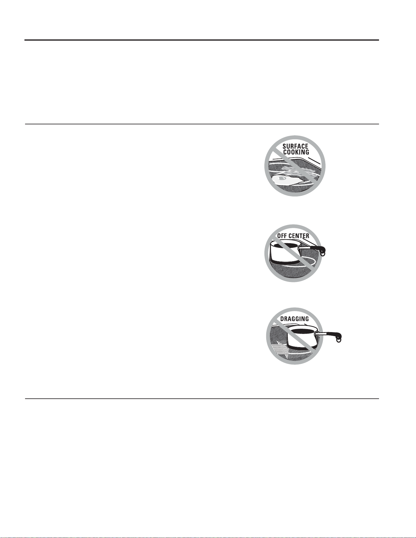
Never cook directly on the glass.
Always use cookware.
Always place the pan in the center of
the surface unit you are cooking on.
Do not slide cookware across the cooktop
EHFDXVHLWFDQVFUDWFKWKHJODVV³WKHJODVV
is scratch-resistant, not scratch proof.
12
49-80773
Cookware for Radiant Glass Cooktop
USING THE RANGE: Cookware for Radiant Glass Cooktop
The following information will help you choose cookware which will give good performance on glass cooktops.
NOTE: Follow all cookware manufacturer’s recommendations when using any type of cookware on the ceramic cooktop.
Stainless Steel:
recommended
Aluminum:
heavy weight recommended
Good conductivity. Aluminum residues
sometimes appear as scratches on the
cooktop but can be removed if cleaned
immediately. Because of its low melting
point, thin weight aluminum should not
be used.
Copper Bottom:
recommended
Copper may leave residues which can
appear as scratches. The residues can
be removed, as long as the cooktop
is cleaned immediately. However, do
not let these pots boil dry. Overheated
metal can bond to glass cooktops. An
overheated copper bottom pot will leave
a residue that will permanently stain the
cooktop if not removed immediately.
Porcelain Enamel on Cast Iron:
recommended if bottom of pan is coated
Porcelain Enamel on Steel:
not recommended
Heating empty pans can cause
permanent damage to cooktop glass.
The enamel can melt and bond to the
ceramic cooktop.
Glass-ceramic:
not recommended
Poor performance. Will scratch the
surface.
Stoneware:
not recommended
Poor performance. May scratch the
surface.
Cast Iron:
not recommended—unless designed
specifically for glass cooktops
Poor conductivity and slow to absorb
heat. Will scratch the cooktop surface.
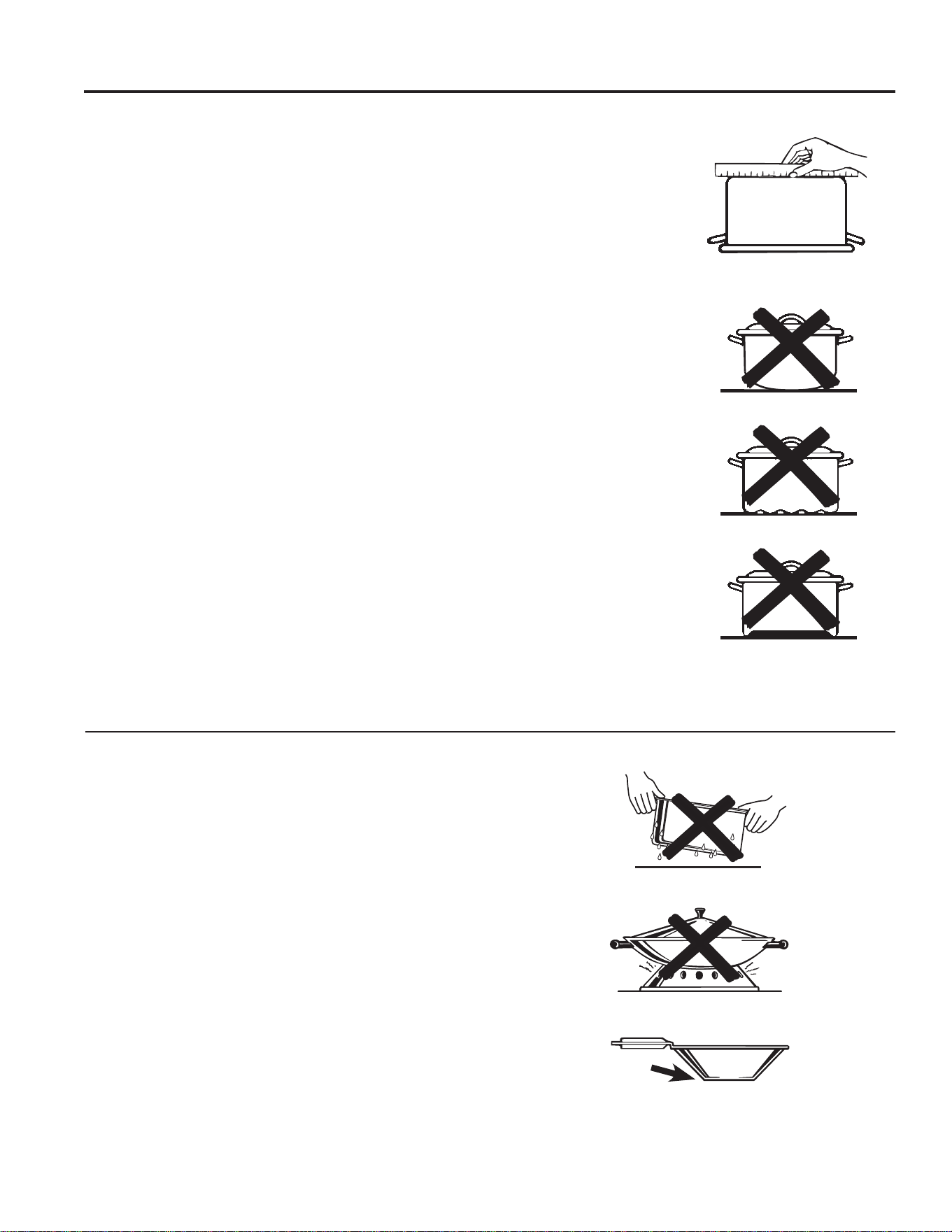
Check pans for flat bottoms by using
a straight edge.
Pans with rounded, curved, ridged or
warped bottoms are not recommended.
Do not place wet pans on the glass cooktop.
Do not use woks with support rings on the
glass cooktop.
Use flat-bottomed woks on the glass cooktop.
For Best Results
Ŷ 3ODFHRQO\GU\SDQVRQWKHVXUIDFHHOHPHQWV'RQRW
place lids on the surface elements, particularly wet
lids. Wet pans and lids may stick to the surface when
cool.
Ŷ 'RQRWXVHZRNVWKDWKDYHVXSSRUWULQJV7KLVW\SHRI
wok will not heat on glass surface elements.
Ŷ :HUHFRPPHQGWKDW\RXXVHRQO\DIODWERWWRPHG
wok. They are available at your local retail store. The
bottom of the wok should have the same diameter as
the surface element to ensure proper contact.
Ŷ 6RPHVSHFLDOFRRNLQJSURFHGXUHVUHTXLUHVSHFLILF
cookware such as pressure cookers or deep-fat
fryers. All cookware must have flat bottoms and be
the correct size.

49-80773
13
1. Upper Oven and Lower Oven: Designates
which oven the controls will operate.
2. Convection Cooking Modes: Convection
cook modes use increased air circulation to improve
performance. The type of benefit depends on the
mode. Your oven has the following convection
cooking modes: Convection Bake and Convection
Roast. See the Cooking Modes section for more
information.
3. Traditional Cooking Modes: Your oven has
the following traditional cooking modes: Bake, Broil
Hi/Lo and Warm. See the Cooking Modes section
for more information.
4. Self Clean: See the Cleaning the Oven section
for important information about using this mode.
5. Start: Must be pressed to start any cooking,
cleaning, or timed function.
6. Cancel/Off: Cancels ALL oven operations except
the clock and timer.
7. Clock: Sets the oven clock time. Press the Set
Clock or 9 and 0 pads and hold for 3 seconds. Use
the number pads to program the clock. Press Start
to save the time.
8. Timer: Works as a countdown timer. Press the
Timer pad and the number pads to program the
time in hours and minutes. Press the Start pad.
If the oven is on, it will not turn off when the timer
countdown is complete. To turn the timer off press
the Timer pad.
9. Delay Time: Delays when the oven will turn
on. Use this to set a time when you want the oven
to start. Press the Delay Time pad and use the
number pads to program the time of day for the
oven to turn on then press Start. Press the desired
cooking mode and temperature then press Start.
A cook time may also be programmed if desired.
Follow the directions under Cook Time for setting
this feature. This can only be used with Bake,
Convection Bake, Convection Roast and Self-Clean.
NOTE: When using the delay time feature, foods
that spoil easily—such as milk, eggs, fish, stuffings,
poultry and pork—should not be allowed to sit for
more than 1 hour before or after cooking. Room
temperature promotes the growth of harmful bacteria.
Be sure that the oven light is off because heat from
the bulb will speed harmful bacteria growth.
10. Cook Time: Counts down cooking time and turns
off the oven when the cooking time is complete.
Press the Cook Time pad, use the number pads to
program a cooking time in hours and minutes, then
press Start. This can only be used with Traditional
Bake, Convection Bake, and Convection Roast.
11. Oven Light(s): Turns the oven light(s) on or off
in both ovens. Note that lights in both ovens will not
turn on if the door is opened while the other oven is
in a clean mode.
12. Lock Controls: Locks out the control so that
pressing the pads does not activate the controls.
Press and hold the Lock Controls pad for three
seconds to lock or unlock the control. Cancel/Off is
always active, even when the control is locked.
13. Chef Connect: Pairs your range with compatible
hood or over-the-range microwave. To pair devices,
hold the 6 and 7 pads for 3 seconds. Bluetooth
®
icon will flash while pairing and remain lit once
paired. This feature will synchronize clocks on both
devices and turn on the fan and lights whenever a
burner is active. Press again to disable feature, and
hold for 3 seconds to un-pair devices.
USING THE RANGE: Double Oven Controls
Double Oven Controls
15 5 18
2
3
46 6
3
10 1011 12 13
9974

14
49-80773
Special Features
USING THE RANGE: Special Features
There are several different special features on your range.
Ŷ 7RHQWHUWKH6SHFLDO)HDWXUHVPHQXSUHVVWKHBake and Broil pads at the same time and hold for three
seconds. "OFFSEt" will appear in the display.
Ŷ 6FUROOWKURXJK6SHFLDO)HDWXUHVPHQXXVLQJWKH8 pad for down and the 3 pad for up.
Ŷ 7RVHOHFWDIHDWXUHWRFKDQJHRUWRFRQILUPDFKDQJHSUHVVWKH0 pad.
Ŷ 7RFDQFHODFKDQJHDQGUHWXUQWRWKH6SHFLDO)HDWXUHVPHQXSUHVVWKH6 pad. To exit the Special Features
menu, press the 6 pad again.
Adjust the Oven Temperature (OFFSEt)
This feature allows the oven baking and convection
baking temperature to be adjusted up to 35ºF hotter
or down to 35ºF cooler. Use this feature if you believe
your oven temperature is too hot or too cold and wish to
change it. This adjustment affects Bake and Convection
Bake modes. No other cooking modes are affected.
Using the number pads to navigate as described above,
select "OFFSEt". A number between positive and
negative 35 will display. Use the 8 or 3 pads to increase
or decrease the offset value. Save and confirm by
pressing the 0 pad.
End of Timer Signals (End tonE)
This is the tone that signals the end of a timer. The tone
can be continuous (Con bEEP) or one repeating beep
(bEEP). A continuous setting will continue to sound a
tone until a button on the control is pressed.
Fahrenheit or Celsius Temperature Display
(dEg Unit)
The oven control is set to use Fahrenheit temperatures
(F), but you can change it to use Celsius temperatures (C).
Clock Configuration (Cloc cFg)
This feature specifies how the time of day will be
displayed. You can select a standard 12-hour clock (12 H)
or 24-hour military time (24 H).
Clock Display (Cloc diSP)
This feature specifies whether the clock appears in the
display. It may be On or Off.
Auto Recipe Conversion (Auto rEciPE)
When using Convection Bake cooking, Auto Recipe
Conversion will automatically convert the regular baking
temperatures entered to convection bake cooking
temperatures when turned on. Note that this option does
not convert convection bake cooking times, it only converts
temperatures. This feature may be turned On or Off.
Sound Volume (Sound)
This feature allows the oven tone volume to be adjusted
between high (Hi), medium (Reg), low (lo), and off (Off).
The control will sound the oven tone at the new volume
level each time the sound level is changed.
12-hour Shutoff (2H ShutoFF)
This feature shuts the oven down after 12 hours of
continuous operation. It may be enabled or disabled.
49-80773
15
Sabbath Mode
The Sabbath mode feature complies with standards set forth by Star K. Some of these standards that will be noticed
by the consumer include the disabling of tones, disabling of oven lights, and delays of about 30 seconds to one
minute on display changes. Only continuous baking or timed baking is allowed in the Sabbath mode. Cooking in the
Sabbath mode is a two-step process, first the Sabbath mode must be set and then the bake mode must be set.
Setting the Sabbath Mode
1. Press the Bake and Broil pads at the same time and
hold until the special features menu is displayed.
2. Use the 3 or 8 number pads to scroll through the
special features until “SAbbAth” is displayed and then
press 0. Refer to the graphic in the Special Features
section to see how the number keys are mapped.
3. Use the 3 or 8 number pads to scroll through the
options until “On” is shown in the display, then press
the 0 number pad to save the setting. Press 6 to exit
the Special Features menu. A single bracket “]” will
appear in the display indicating that the Sabbath mode
is set. The clock will not be displayed. Continuous
bake or timed bake can now be programmed.
Starting a Continuous Bake
1. Press the Bake pad.
2. If the desired temperature is 350F, press Start. If
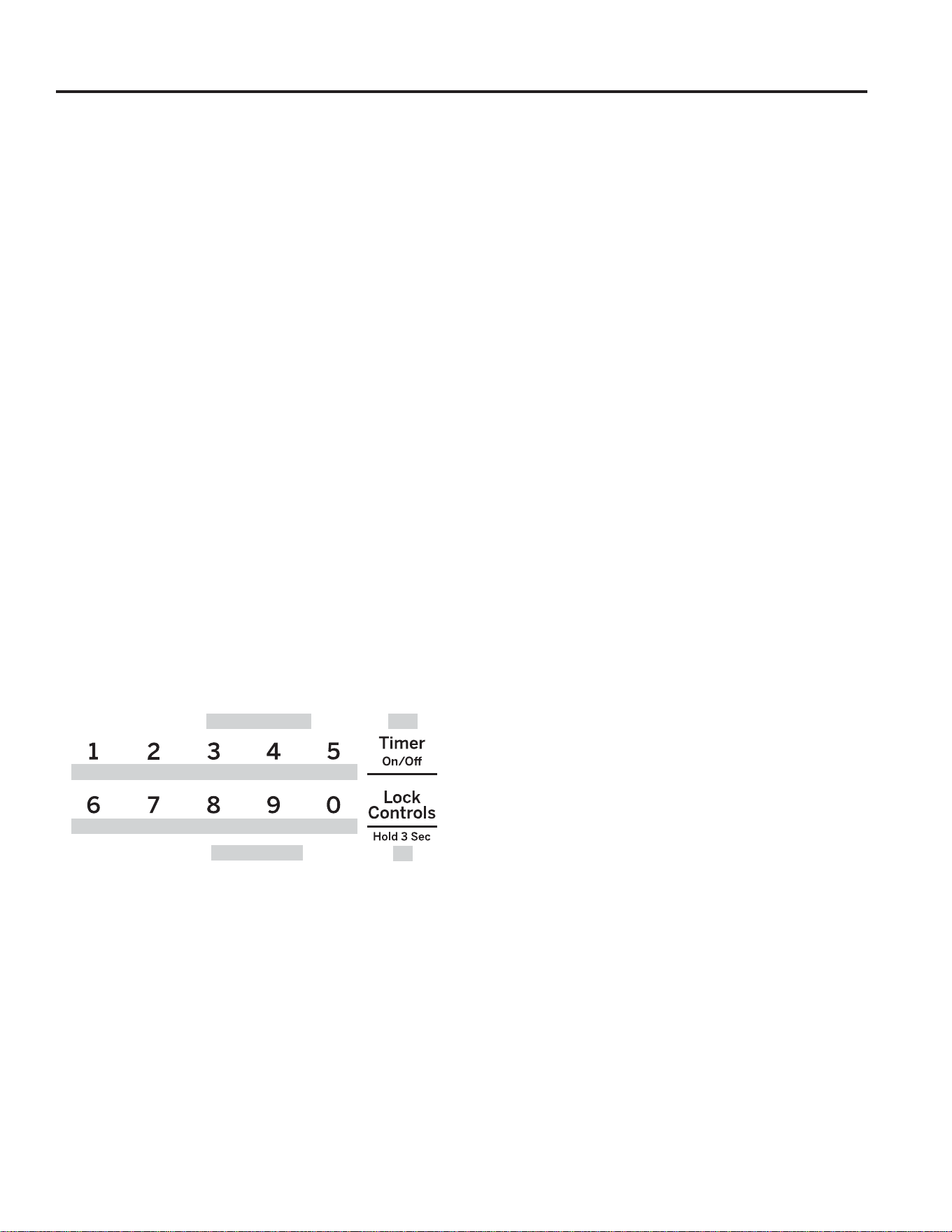
a different cooking temperature is desired, use the
1 through 5 number pads or Timer pad to select a
preset cooking temperature, then press Start. Refer
to the graphic below to determine which pad sets the
desired cooking temperature.
After a delay, a second bracket “] [“ will appear in the
display indicating that the oven is baking.
Adjusting the Temperature
1. Press Bake, use the 1 through 5 number pads and
the Timer pad to select a different preset cooking
temperature, and press Start.
2. Since no feedback is given during temperature
change, an oven thermometer can be used to confirm
temperature changes.
Starting a Timed Bake
1. Press the Bake pad.
2. If the desired temperature is 350F, use the 6 through
0 number pads or the Lock Control pad to select
a cooking time. If a cooking temperature other
than 350F is desired, use the 1 through 5 number
pads or the Timer pad to select a preset cooking
temperature, then select the cooking time. Refer to
the graphic on this page to determine which pad sets
the desired cooking temperature and cooking time.
3. Press Start.
After a delay, a second bracket “] [“ will appear in the
display indicating that the oven is baking. When the cook
time expires, the display will change back to a single
bracket “]” indicating that the oven is no longer baking.
No tone will sound when the cook time is complete.
Exit the Sabbath Mode
Exiting the Sabbath mode should be done after the
Sabbath is over.
1. Press Cancel/Off to end any bake mode that may be
running.
2. Press Bake and Broil pads at the same time and
hold until the Special Features menu is displayed.
3. Use the 3 or 8 number pads to scroll through the
special features until “SAbbAth” is displayed, then
press 0.
4. Use the 3 or 8 number pads to scroll through the
options until “OFF” is displayed and press 0 to save
the setting. Press the 6 number pad to exit the
Special Features menu.
Sabbath Mode Power Outage Note
If a power outage occurs while the oven is in Sabbath
Mode, the unit will return to Sabbath Mode when power
is restored, however the oven will return to the off state
even if it was in the middle of a bake cycle when the
power outage occurred.
USING THE OVEN: Sabbath Mode
1 = 170° F, 2 = 200° F, 3 = 250° F, 4 = 300° F, 5 = 325° F, Timer = 400° F
6 = 2 hours, 7 = 2.5 hours, 8 = 3 hours, 9 = 3.5 hours,
0 = 4 hours, Lock Controls = 6 hours
Temperature (°F) 400
Time (hours)
6h
170
2h
200
2.5h
250
3h
300
3.5h
325
4h
16
49-80773
Recommended rack positions for various types of
foods are provided in the Cooking Guide. Adjusting
rack position is one way to impact cooking results. For
example, if you would prefer darker tops on cakes,
muffins, or cookies, try moving food one rack position
higher. If you find foods are too brown on top try moving
them down next time.
When baking with multiple pans and on multiple racks,
ensure there is at least 3.8 cm (1½") between pans to
allow sufficient space for air to flow.
Your Oven may have extension racks and/or traditional
flat racks.
To avoid possible burns, place the racks in the desired
position before you turn the oven on.
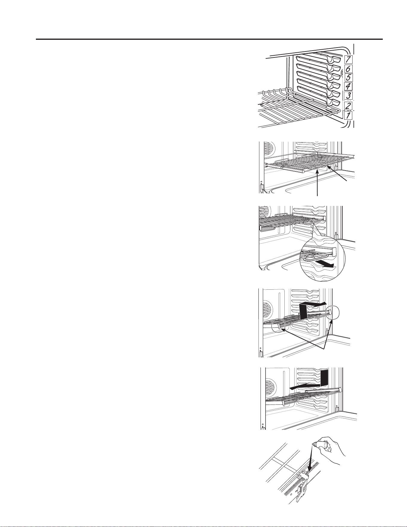
Extension Racks
Always pull the rack out by its upper front rail to its fully
open position, when placing or removing cookware.
If extension racks are difficult to extend, lubricate the
racks with the graphite lubricant provided with your oven.
Remove the rack from the oven,remove debris in the
side tracks with paper towel, shake the graphite lubricant
and place 4 small drops on the two bottom tracks of the
left and right sides. Open and close the rack several
times to distribute the lubricant.
To order additional graphite lubricant, read the
Assistance and Accessories section at the beginning of
the manual.
To Remove An Extension Rack:
1. Make sure the rack is pushed all the way into
the oven so that side paddles on the rack from
disengaged with oven support.
2. Slide the rack toward you to the bump (stop position)
on the rack support.
3. Firmly grasp both sides of the rack frame and the
sliding rack, tilt the front end up and pull it out.
To Replace An Extension Rack:
1. Firmly grasp both sides of the rack frame and the
sliding rack.
2. Place the curved end of the rack (stop-locks) onto the
oven supports, tilt up the front of the rack and push it
in as far as it will go.
If extension racks are difficult to replace or remove, wipe
the oven rack supports with cooking oil. Do not wipe oil
on the rack slides.
To Lubricate the Paddle:
Shake lubricant and apply to the moving parts of the
paddle mechanisms as shown.
The number of rack positions may vary by model.
Upper Front
Rail
Fully Open Position
Grasp here
USING THE RANGE: Oven Racks
Oven Racks

49-80773
17
USING THE RANGE: Aluminum Foil and Oven Liners / Cookware
Cookware
Cookware Guidelines
The material, finish, and size of cookware affect baking
performance.
Dark, coated and dull pans absorb heat more readily
than light, shiny pans. Pans that absorb heat more
readily can result in a browner, crisper, and thicker crust.
If using dark and coated cookware check food earlier
than minimum cook time. If undesirable results are
obtained with this type of cookware consider reducing
oven temperature by 13.9º C (25º F) next time.
Shiny pans can produce more evenly cooked baked
goods such as cakes and cookies.
Glass and ceramic pans heat slowly but retain heat well.
These types of pans work well for dishes such as pies
and custards.
Air insulated pans heat slowly and can reduce bottom
browning.
Keep cookware clean to promote even heating.
CAUTION: Do not use any type of foil or oven liner to cover the oven bottom. These items can trap
heat or melt, resulting in damage to the product and risk of shock, smoke or fire. Damage from improper use
of these items is not covered by the product warranty.
Foil may be used to catch spills by placing a sheet on a lower rack, several inches below the food. Do not use more
foil than necessary and never entirely cover an oven rack with aluminum foil. Keep foil at least 1-1/2” from oven walls
to prevent poor heat circulation.
Aluminum Foil and Oven Liners

18
49-80773
Your new oven has a variety of cooking modes to help you get the best results. These modes are described below.
Refer to the Cooking Guide section for recommendations for specific foods. Remember, your new oven may perform
differently than the oven it is replacing.
Baking and Roasting Modes
Select a mode for baking and roasting based on the
type and quantity of food you are preparing. When
preparing baked goods such as cakes, cookies, and
pastries always preheat the oven first. Follow recipe
recommendations for food placement. If no guidelines
are provided, center food in the oven.
Traditional Bake
The traditional bake mode is intended for single rack
cooking. This mode uses heat primarily from the lower
element but also from the upper element to cook
food. To use this mode press the Bake pad, enter
a temperature, and then press Start. Preheating is
generally recommended when using this mode.
Convection Bake
The Convection Bake mode is intended for baking on
multiple racks at the same time. This mode uses heat
primarily from the rear element but also heat from the
upper and lower elements, along with air movement
from the convection fan to enhance cooking evenness.
Your oven is equipped with Auto Recipe Conversion,
so it is not necessary to convert the temperature when
using this mode. Baking time might be slightly longer for
multiple racks than what would be expected for a single
rack. To use this mode press the Convection Bake
pad, enter a temperature, and then press Start. Always
preheat when using this mode.
Convection Roast
The Convection Roast mode is intended for roasting
whole cuts of meat on a single rack. This mode uses
heat from the lower, upper, and rear elements along
with air movement from the convection fan to improve
browning and reduce cooking time. It is not necessary to
convert temperature. Check food earlier than the recipe
suggested time when using this mode or use a meat
probe. To use this mode press the Convection Roast
pad, enter a temperature, and then press Start. It is not
necessary to preheat when using this mode.
Broiling Modes
Broiling is available in both ovens. For better broiling,
the lower oven is recommended. When broiling in the
upper oven, the door should remain CLOSED. When
broiling in the lower oven, the door should remain OPEN.
Monitor food closely while broiling. Use caution when
broiling on upper rack positions as placing food closer to
the broil element increases smoking, spattering, and the
possibility of fats igniting. For best performance center
food below the broil heating element. Broiling on rack
position 7 is not recommended.
Try broiling foods that you would normally grill. Adjust
rack positions to adjust the intensity of the heat to the
food. Place foods closer to the broil element when a
seared surface and rare interior is desired. Thicker foods
and foods that need to be cooked through should be
broiled on a rack position farther from the broiler or by
using Broil Lo.
Broil Hi
The Traditional Broil Hi mode uses intense heat from the
upper element to sear foods. Use Broil Hi for thinner cuts
of meat and/or foods you prefer less done on the interior.
To use this mode press the Broil pad once and then
press Start. It is not necessary to preheat when using
this mode.
Broil Lo
The Traditional Broil Lo mode uses less intense heat
from the upper element to cook food thoroughly while
also producing surface browning. Use Broil Lo for thicker
cuts of meat and/or foods that you would like cooked
all the way through. To use this mode press the Broil
pad twice and then press Start. It is not necessary to
preheat when using this mode.
Warm
Warm mode is designed to keep hot foods hot for up to
3 hours. To use this mode, press the Warm pad then
press Start. Cover foods that need to remain moist and
do not cover foods that should be crisp. Preheating is
not required. Do not use warm to heat cold food other
than crisping crackers, chips or dry cereal. It is also
recommended that food not be kept warm for more
than 2 hours.
USING THE RANGE: Cooking Modes
Cooking Modes
49-80773
19
FOOD TYPE
RECOMMENDED
MODE(S)
RECOMMENDED
RACK POSITION(S) ADDITIONAL SUGGESTIONS
Baked Goods
Layer cakes, sheet cakes,
bundt cakes, muffins, quick
breads on a Single Rack
Bake 4 Use shiny cookware.
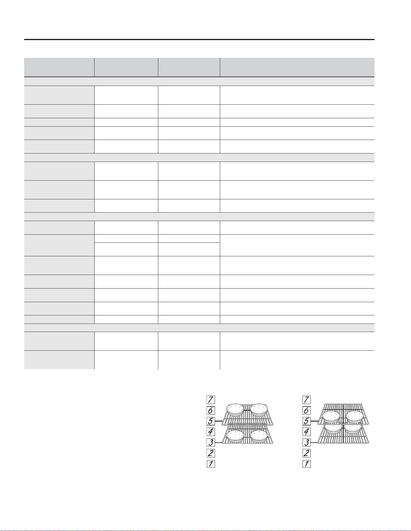
Layer cakes* on Multiple
Racks
Bake
Convection Bake
3 and 5
Ensure adequate airflow
(see illustration below).
Chiffon cakes (angel food) Bake 1 Use shiny cookware.
Cookies, biscuits, scones
on a Single Rack
Bake 4 Use shiny cookware.
Cookies, biscuits, scones
on Multiple Racks
Convection Bake
3 and 5
2, 4 and 6
Ensure adequate airflow.
Beef & Pork
Hamburgers Broil Hi 6
Use a broil pan; move food down for more doneness/less searing. Watch
food closely when broiling. For best performance center food below the broil
heating element.
Steaks & Chops Broil Hi 6
Use a broil pan; move food down for more doneness/less searing. Watch
food closely when broiling. For best performance center food below the broil
heating element.
Roasts
Bake
Convection Roast
3 or 4 Use a low sided pan such as a broil pan. Preheating is not necessary.
Poultry
Whole chicken
Bake
Convection Roast
3 or 4 Use a low sided pan such as a broil pan.
Bone-in chicken breasts,
legs, thighs
Broil Hi 2
If breaded or coated in sauce avoid Broil Hi modes. Broil skin side down first.
Watch food closely when broiling. For best performance when broiling, center
food below the broil heating element.
Broil Lo
Bake
2 or 3
Boneless chicken breasts
Broil Lo
Bake
2 or 3
Move food down for more doneness/less searing and up for greater searing/
browning when broiling. For best performance when broiling, center food
below the broil heating element.
Whole turkey
Bake
Convection Roast
1 or 2 Use a low sided pan such as a broil pan.
Turkey breast
Bake
Convection Roast
2 or 3 Use a low sided pan such as a broil pan.
Fish Broil Lo
6 (1.3 cm [1/2"] thick or less)
5 (>
1.3 cm [1/2"]
)
Watch food closely when broiling. For best performance center food below the
broil heating element.
Casseroles Bake 3 or 4
Frozen Convenience Foods
Pizza, potato products,
chicken nuggets, appetizers
on a Single Rack
Bake 3 or 4 Use shiny cookware.
Pizza, potato products,
chicken nuggets, appetizers
on Multiple Racks
Convection Bake 3 and 5 Use shiny cookware.
*When baking four cake layers at a time with traditional
bake, use racks 3 and 5.
*When baking four cake layers at a time with convection
bake, use racks 3 and 5.
Cook food thoroughly to help protect against food
borne illness. Minimum safe food temperature
recommendations for food safety can be found at
www.IsItDoneYet.gov. Make sure to use a food
thermometer to take food temperatures.
Rack position for Traditional
Bake, cakes in front of rack 3
and back of rack 5
Rack position for Convection
Bake, cakes in back of rack 3
and front of rack 5
Cooking Guide
USING THE RANGE: Cooking Guide
Lower Cavity for Double Oven Models
20
49-80773
FOOD TYPE
RECOMMENDED
MODE(S)
RECOMMENDED
RACK POSITION(S) ADDITIONAL SUGGESTIONS
Baked Goods
Layer cakes, sheet cakes,
muffins, baked on Single Rack
Bake 1 Use shiny cookware.
Cookies, biscuits, scones on a
Single Rack
Bake 1 Use shiny cookware.
Beef & Pork
Hamburgers Broil Hi 1
Use a broil pan; move food down for more done-
ness/less searing. Watch food closely when broiling.
For best performance center food below the broil
heating element.
Steaks & Chops Broil Hi 1
Use a broil pan; move food down for more done-
ness/less searing. Watch food closely when broiling.
For best performance center food below the broil
heating element.
Poultry
Bone-in chicken breasts, legs,
thighs
Broil Lo
Bake
1
Broil skin side down first. Watch food closely when
broiling. For best performance when broiling, center
food below the broil heating element.
Boneless chicken breasts
Broil Lo
Bake
1
For best performance when broiling, center food
below the broil heating element.
Fish Broil Lo 1
Watch food closely when broiling. For best perfor-
mance center food below the broil heating element.
Frozen Convenience Foods
Pizza, french fries, tator tots,
chicken nuggets, appetizers
on a Single Rack
Bake 1 Use shiny cookware.
Upper Cavity for Double Oven Models
USING THE RANGE: Cooking Guide
Cooking Guide (Cont.)
NOTE: For better broiling, the lower oven is recommended.

49-80773
21
Cleaning the Range – Exterior
CARE AND CLEANING: Cleaning the Range – Exterior
If your range is removed for cleaning, servicing or any reason, be
sure the anti-tip device is reengaged properly when the range is
replaced. Failure to take this precaution could result in tipping of the
range and can result in death or serious burns to children or adults.
WARNING
Be sure all controls are off and all surfaces are cool before cleaning any part of the range.
Control Knobs
The control knobs may be removed for easier cleaning.
Make sure the knobs are in the OFF positions and pull
them straight off the stems for cleaning.
The knobs can be cleaned in a dishwasher or they may
also be washed with soap and water.
Make sure the inside of the knobs are dry before
replacing.
Replace the knobs, in the OFF position to ensure proper
placement.
Control Lockout
If desired, the touch pads may be deactivated before
cleaning.
See How to Lock Out the Controls in the Using the clock,
kitchen timer and control lockout section in this manual.
Clean up splatters with a damp cloth.
You may also use a glass cleaner.
Remove heavier soil with warm, soapy water. Do not use
abrasives of any kind.
Reactivate the touch pads after cleaning.
Control Panel
It’s a good idea to wipe the control panel after each use.
Clean with mild soap and water or vinegar and water,
rinse with clean water and polish dry with a soft cloth.
Do not use abrasive cleansers, strong liquid cleansers,
plastic scouring pads or oven cleaners on the control
panel—they will damage the finish.
Oven Exterior
Do not use oven cleaners, abrasive cleansers, strong
liquid cleansers, steel wool, plastic scouring pads, or
cleaning powders on the interior or exterior of the oven.
Clean with a mild soap and water or vinegar and water
solution. Rinse with clean water and dry with a soft cloth.
When cleaning surfaces, make sure that they are at
room temperature and not in direct sunlight.
If stain on the door vent trim is persistent, use a mild
abrasive cleaner and a sponge-scrubber for best results.
Spillage of marinades, fruit juices, tomato sauces and
basting liquids containing acids may cause discoloration
and should be wiped up immediately. Let hot surfaces
cool, then clean and rinse.
Painted Surfaces
Painted surfaces include the sides of the range, the doors
and top of control panel. Clean these with soap and water
or a vinegar and water solution.
Do not use commercial oven cleaners, cleaning powders,
steel wool or harsh abrasives on any painted surface.
Stainless Steel Surfaces (on some models)
Do not use a steel wool pad; it will scratch the surface.
To clean the stainless steel surface, use warm sudsy
water or a stainless steel cleaner or polish. Always wipe
the surface in the direction of the grain. Follow the cleaner
instructions for cleaning the stainless steel surface.
To inquire about purchasing cleaning products including
stainless steel appliance cleaner or polish read the
Assistance and Accessories sections at the beginning of
this manual.
Porcelain Enamel Cooktop
The porcelain enamel finish is sturdy but breakable if
misused. This finish is acid-resistant. However, any acidic
foods spilled (such as fruit juices, tomato or vinegar)
should not be permitted to remain on the finish.
If acids spill on the cooktop while it is hot, use a dry paper
towel or cloth to wipe it up right away. When the surface
has cooled, wash with soap and water. Rinse well.
For other spills such as fat spatterings, wash with soap
and water or cleansing powders after the surface has
cooled. Rinse well. Polish with a dry cloth.

22
49-80773
The interior of your new oven can be cleaned manually or by using Self Clean.
Spillage of marinades, fruit juices, tomato sauces and basting liquids containing acids may cause discoloration and
should be wiped up immediately. Let hot surfaces cool, then clean and rinse.
Manual Cleaning
Do not use oven cleaners, abrasive cleaners, strong
liquid cleansers, steel wool, scouring pads, or cleaning
powders on the interior of the oven. Clean with a mild
soap and water or vinegar and water solution. Rinse with
clean water and dry with a soft cloth. When cleaning
surfaces, make sure that they are at room temperature.
Self Clean Mode
Read Self-Cleaning Oven Safety Instructions at the
beginning of this manual before using Self Clean Mode.
Self clean uses very high temperatures to clean the oven
interior. The oven door will lock when using this feature.
Before operating the self-clean cycle, wipe up grease and
soils from the oven. Remove all items from the oven other
than enameled (dark color) racks. Shiny or silver racks
and any cookware or other items should all be removed
from the oven before initiating a self-clean cycle. Close
the door. Press the Self Clean pad and a default self-
clean time is displayed. The clean time can be changed
to any time between 3:00 and 5:00 hours by using the
number pads to enter a different time and pressing Start.
For heavily soiled ovens, the maximum 5 hour clean time
is recommended. If you wish to use the default time, press
the Start pad immediately after pressing the Self Clean
pad. The oven will turn off automatically when the self-
clean cycle is complete. The door will stay locked until the
oven has cooled down. After the oven has cooled down
wipe any ash out of the oven.
We recommend venting your kitchen with an open
window or using a ventilation fan or hood during the first
self-clean cycle.
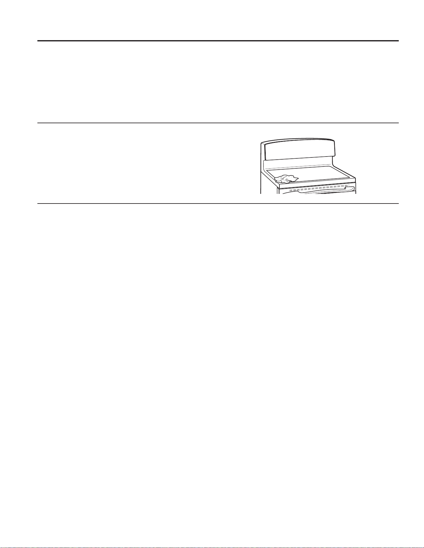
Soil on the front frame of the range and outside the
gasket on the door will need to be cleaned by hand.
Clean these areas with hot water, soap-filled steel-wool
pads or cleansers such as Soft Scrub
®
. Rinse well with
clean water and dry.
Do not clean the gasket. The fiberglass material of
the oven door gasket cannot withstand abrasion. It is
essential for the gasket to remain intact. If you notice it
becoming worn or frayed, replace it.
Make sure the oven light bulb cover is in place and the
oven light is off.
IMPORTANT: The health of some birds is extremely
sensitive to the fumes given off during the self-cleaning
cycle of any range. Move birds to another well-
ventilated room.
On Some Models:
The surface units are automatically disabled during the
self-clean cycle. Make sure that all surface unit controls
are turned off at all times during the self-clean cycle.
Any surface unit that is set to an “on” position while the
self-clean cycle is operating will automatically come on
after the self-clean cycle is finished, and could result in
an “on” unattended surface unit. Wait until the self-clean
cycle is finished to set and use the surface units.
CARE AND CLEANING: Cleaning the Range – Interior
Cleaning the Range – Interior
Flat Racks
Flat racks can be left in the cavity during self-clean
(if enameled racks, not shiny) or can be washed with
warm, soapy water.
Racks may be more difficult to slide, especially after
a self-clean. Put some vegetable oil on a soft cloth or
paper towel and rub onto the left and right edges.
Oven Heating Elements
Do not clean the bake element or the broil element. Any
soil will burn off when the elements are heated.
To clean the oven floor when the bake element is
exposed, gently lift the bake element. In some models,
the bake element is not exposed and is under the oven
floor. Clean the oven floor with warm, soapy water.
Wipe up heavy soil on the oven bottom.
49-80773
23
Use a CERAMA BRYTE
®
Cleaning
Pad for Ceramic Cooktops.
Cleaning the Glass Cooktop
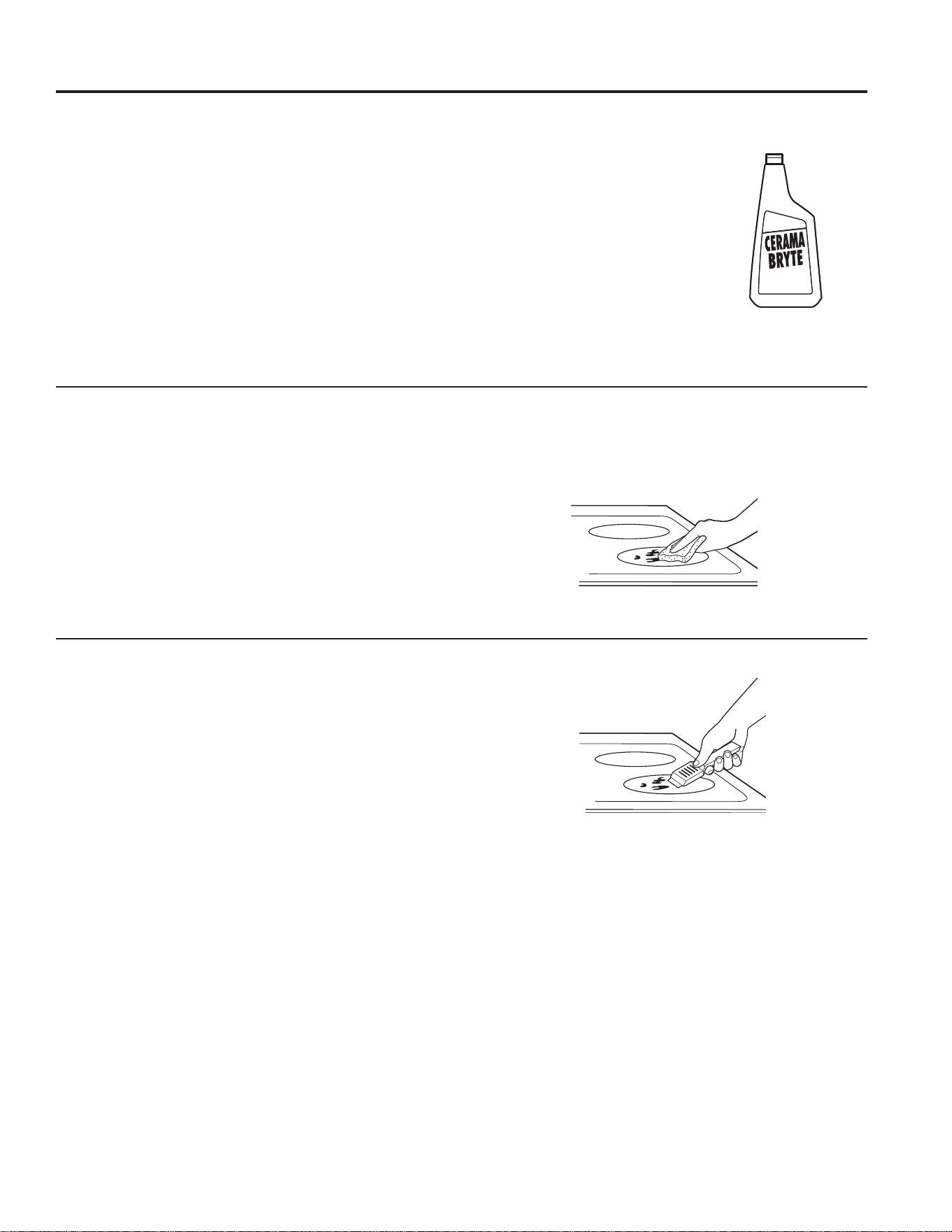
Normal Daily Use Cleaning
ONLY use CERAMA BRYTE
®
Ceramic Cooktop Cleaner
on the glass cooktop. Other creams may not be as
effective.
To maintain and protect the surface of your glass
cooktop, follow these steps:
1. Before using the cooktop for the first time, clean it
with CERAMA BRYTE
®
Ceramic Cooktop Cleaner.
This helps protect the top and makes cleanup easier.
2. Daily use of CERAMA BRYTE
®
Ceramic Cooktop
Cleaner will help keep the cooktop looking new.
3. Shake the cleaning cream well. Apply a few drops of
CERAMA BRYTE
®
Ceramic Cooktop Cleaner directly
to the cooktop.
4. Use a paper towel or
CERAMA BRYTE
®
Cleaning
Pad for Ceramic Cooktops
to clean the entire cooktop
surface.
5. Use a dry cloth or paper towel
to remove all cleaning residue.
No need to rinse.
NOTE: It is very important that
you DO NOT heat the cooktop
until it has been cleaned
thoroughly.
Burned-On Residue
NOTE: DAMAGE to your glass surface may occur if you
use scrub pads other than those recommended.
1. Allow the cooktop to cool.
2. Spread a few drops of CERAMA BRYTE
®
Ceramic
Cooktop Cleaner on the entire burned residue area.
3. Using the included CERAMA BRYTE
®
Cleaning Pad
for Ceramic Cooktops, rub the residue area, applying
pressure as needed.
4. If any residue remains, repeat the steps listed above
as needed.
5. For additional protection, after all residue has been
removed, polish the entire surface with CERAMA
BRYTE
®
Ceramic Cooktop Cleaner and a paper towel.
Heavy, Burned-On Residue
1. Allow the cooktop to cool.
2. Use a single-edge razor blade scraper at approximately
a 45° angle against the glass surface and scrape the
soil. It will be necessary to apply pressure to the razor
scraper in order to remove the residue.
3. After scraping with the razor scraper, spread a few drops
of CERAMA BRYTE
®
Ceramic Cooktop Cleaner on the
entire burned residue area. Use the CERAMA BRYTE
®
Cleaning Pad to remove any remaining residue.
4. For additional protection, after all residue has been
removed, polish the entire surface with CERAMA
BRYTE
®
Ceramic Cooktop Cleaner and a paper towel.
Clean your cooktop after each
spill. Use CERAMA BRYTE
®
Ceramic Cooktop Cleaner.
The CERAMA BRYTE
®
Ceramic Cooktop Scraper and all
recommended supplies are available through our Parts Center.
See instructions under “To Order Parts” section on next page.
NOTE: Do not use a dull or nicked blade.
CARE AND CLEANING: Cleaning the Glass Cooktop
24
49-80773
Metal Marks and Scratches
1. Be careful not to slide pots and pans across your
cooktop. It will leave metal markings on the cooktop
surface.
These marks are removable using the CERAMA
BRYTE
®
Ceramic Cooktop Cleaner with the CERAMA
BRYTE
®
Cleaning Pad for Ceramic Cooktops.
2. If pots with a thin overlay of aluminum or copper
are allowed to boil dry, the overlay may leave black
discoloration on the cooktop.
This should be removed immediately before heating
again or the discoloration may be permanent.
NOTE: Carefully check the bottom of pans for roughness
that would scratch the cooktop.
Damage from Sugary Spills and Melted Plastic
Special care should be taken when removing hot substances to avoid permanent damage of the glass surface.
Sugary spillovers (such as jellies, fudge, candy, syrups) or melted plastics can cause pitting of the surface of your
cooktop (not covered by the warranty) unless the spill is removed while still hot. Special care should be taken when
removing hot substances.
Be sure to use a new, sharp razor scraper.
Do not use a dull or nicked blade.
1. Turn off all surface units. Remove hot pans.
2. Wearing an oven mitt:
a. Use a single-edge razor blade scraper (CERAMA
BRYTE
®
Ceramic Cooktop Scraper) to move the
spill to a cool area on the cooktop.
b. Remove the spill with paper towels.
3. Any remaining spillover should be left until the surface
of the cooktop has cooled.
4. Don’t use the surface units again until all of the
residue has been completely removed.
NOTE: If pitting or indentation in the glass surface has
already occurred, the cooktop glass will have to be
replaced. In this case, service will be necessary.
Cooktop Seal
To clean the cooktop seal around the edges of the glass,
lay a wet cloth on it for a few minutes, then wipe clean
with nonabrasive cleaners.
CARE AND CLEANING: Cleaning the Glass Cooktop
Cleaning the Glass Cooktop (Cont.)
49-80773
25
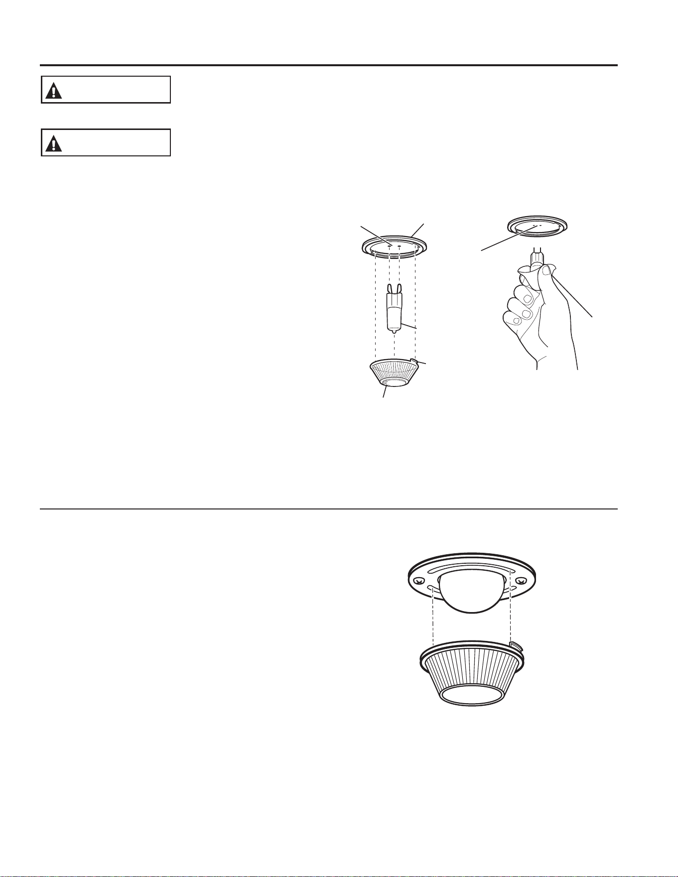
Use
gloves or
cloth
Receptacle
G9 Bulb
Socket
Tab
Glass cover
Receptacle
Maintenance
CARE AND CLEANING: Maintenance
SHOCK OR BURN HAZARD: Before replacing oven light bulb, disconnect the electrical
power to the range at the main fuse or circuit breaker panel. Failure to do so may result
in electric shock or burn.
WARNING
BURN HAZARD: The glass cover and bulb should be removed when cool. Touching hot
glass with bare hands or a damp cloth can cause burns.
CAUTION
Oven Light Replacement (on some models)
To remove:
1. Turn the glass cover counterclockwise 1/4 turn until
the tabs of the glass cover clear the grooves of the
socket. Wearing latex gloves may offer a better grip.
2. Using gloves or a dry cloth, remove the bulb by
pulling it straight out.
To replace:
1. Use a new 120/130-volt halogen bulb, not to exceed
50 watts. Replace the bulb with the same type of bulb
that was removed. Be sure the replacement bulb is
rated 120 volts or 130 volts (NOT 12 volts).
2. Using gloves or a dry cloth, remove the bulb from its
packaging. Do not touch the bulb with bare fingers.
Oil from skin will damage the bulb and shorten its life.
3. Push the bulb straight into the receptacle all the way.
4. Place the tabs of the glass cover into the grooves of
the socket. Turn the glass cover clockwise 1/4 turn.
For improved lighting inside the oven, clean the glass
cover frequently using a wet cloth. This should be
done when the oven is completely cool.
5. Reconnect electrical power to the oven.
Oven Light Replacement (on some models)
To remove:
1. Turn the glass cover counterclockwise 1/4 turn until
the tabs of the glass cover clear the grooves of the
socket. Wearing latex gloves may offer a better grip.
2. Remove the bulb by turning it counter-clockwise.
To replace:
1. Replace bulb with a new 40-watt appliance bulb.
Insert the bulb and turn it clockwise until it is tight.
2. Place the tabs of the glass cover into the grooves of
the socket. Turn the glass cover clockwise 1/4 turn.
For improved lighting inside the oven, clean the glass
cover frequently using a wet cloth. This should be
done when the oven is completely cool.
3. Reconnect electrical power to the oven.
26
49-80773
Lift-Off Lower Oven Door
The door is very heavy. Be careful when removing and lifting the door.
Do not lift the door by the handle.
To remove the door:
1. Fully open the door.
2. Pull the hinge locks down toward the door frame, to
the unlocked position. A tool, such as a small flat-
blade screwdriver, may be required.
3. Firmly grasp both sides of the door at the top.
4. Close door to the door removal position. The door
should be open approximately 7.6 cm (3") with no
obstruction above the door.
5. Lift door up and out until both hinge arms are clear of
the slots.
To replace the door:
1. Firmly grasp both sides of the door at the top.
2. Starting on the left side, with the door at the same
angle as the removal position, seat the indentation of
the hinge arm into the bottom edge of the hinge slot.
The notch in the hinge arm must be fully seated into
the bottom of the slot. Repeat for right side.
3. Fully open the door. If the door will not fully open, the
indentation is not seated correctly in the bottom edge
of the slot.
4. Push the hinge locks up against the front frame of the
oven cavity, to the locked position.
5. Close the oven door.
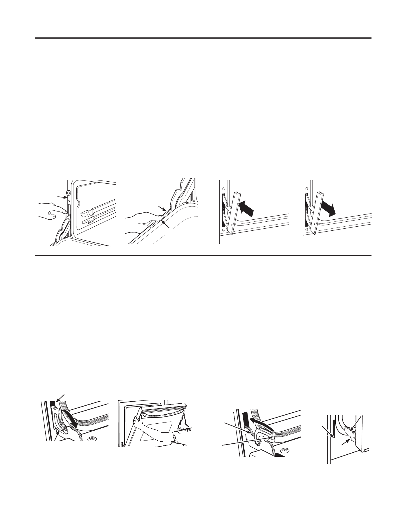
Lift-Off Upper Oven Door
To remove the door:
1. Fully open the door.
2. Lift up on the hinge lock toward the oven frame until
they stop.
3. Close the door to 45 degrees (you will feel the door
stop). The hinge lock will contact the oven frame.
4. On both sides of the door, press down on the release
buttons on each hinge.
5. Lift door up until it is clear of the hinge.
6. Pull on hinge arms slightly to relieve pressure on the
locking tabs.
7. Push the hinge locks down onto the hinge.
8. Push the hinges in toward the unit so they are closed.
To replace the door:
1. Pull the hinges down away from the oven frame to
the fully open position.
2. Lift up on the hinge locks toward the oven frame until
they stop.
3. The hinges will release to the 45-degree position. The
hinge locks will contact the oven frame.
4. Slide the door back onto the hinges. Make sure the
buttons pop back out.
5. Fully open the door.
6. Push the hinge locks down onto the hinge.
7. Close the oven door.
Removal position
Hinge lock
Slot
Pull hinge locks down to unlock
Push hinge locks up to lock
Hinge
lock
Hinge
arm
Indentation
Bottom
edge of
slot
Hinge arm
CARE AND CLEANING: Maintenance
Maintenance (Cont.)
Oven
frame
Door
frame
Release
buttons
Pull down
Push in

49-80773
27
Notes

28
49-80773
Notes

49-80773
29
Notes
30
49-80773
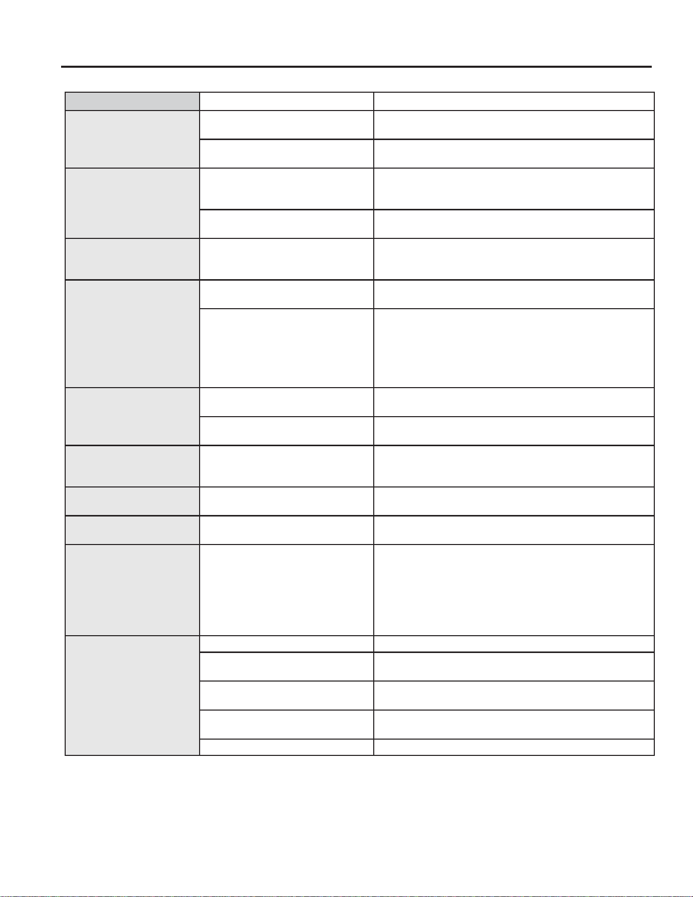
Save time and money! Review the charts on the following pages first and you may not need to call for service.
Problem Possible Cause What To Do
Surface units will not
maintain a rolling boil
or cooking is not fast
enough
Improper cookware being used. Use pans which are flat and match the diameter of the
surface unit selected.
In some areas, the power
(voltage) may be low.
Cover pan with a lid until desired heat is obtained.
Surface units do not
work properly
A fuse in your home may be
blown or the circuit breaker
tripped.
Replace the fuse or reset the circuit breaker.
Cooktop controls improperly set. Check to see the correct control is set for the surface unit
you are using.
Surface unit stops
glowing when turned to
a lower setting
The unit is still on and hot. This is normal.
Scratches (may appear
as cracks) on cooktop
glass surface
Incorrect cleaning methods
being used.
Scratches are not removable. Tiny scratches will become
less visible in time as a result of cleaning.
Cookware with rough bottoms
being used or coarse particles
(salt or sand) were between the
cookware and the surface of the
cooktop. Cookware has been
slid across the cooktop surface.
To avoid scratches, use the recommended cleaning
procedures. Make sure bottoms of cookware are clean
before use, and use cookware with smooth bottoms.
Areas of discoloration
on the cooktop
Food spillovers not cleaned
before next use.
See the Cleaning the glass cooktop section.
Hot surface on a model with a
light-colored cooktop.
This is normal. The surface may appear discolored when it is
hot. This is temporary and will disappear as the glass cools.
Plastic melted to the
surface
Hot cooktop came into contact
with plastic placed on the hot
cooktop.
See the Glass surface—potential for permanent damage
section in the Cleaning the glass cooktop section.
Pitting (or indentation)
of the cooktop
Hot sugar mixture spilled on the
cooktop.
Call a qualified technician for replacement.
Frequent cycling off and
on of surface units
Improper cookware being used. Use only flat cookware to minimize cycling.
My new oven doesn't
cook like my old one.
Is something wrong
with the temperature
settings?
Your new oven has a different
cooking system from your old
oven and therefore may cook
differently than your old oven.
For the first few uses, follow your recipe times and
temperatures carefully. If you still think your new oven
is too hot or too cold, you can adjust the temperature
yourself to meet your specific cooking preference.
NOTE: This adjustment affects Bake, and Convection
Bake temperatures; it will not affect Convection Roast,
Broil or Clean.
Food does not bake
properly
Oven controls improperly set. See the Cooking Modes section.
Rack position is incorrect or
rack is not level.
See the Cooking Modes section and Cooking Guide.
Incorrect cookware or cookware
of improper size being used.
See the Cookware section.
Oven temperature needs
adjustment.
See the Special Features section.
Ingredient substitution Substituting ingredients can change the recipe outcome.
Troubleshooting tips ... Before you call for service
TROUBLESHOOTING TIPS

49-80773
31
Problem Possible Cause What To Do
Food does not broil
properly
Oven controls improperly set. Make sure you select the appropriate broil mode.
Improper rack position being used. See Cooking Guide for rack location suggestions.
Food being cooked in a hot pan. Make sure cookware is cool.
Cookware not suited for broiling. Use a pan specifically designed for broiling.
Aluminum foil used on the broiling
pan and grid has not been fitted
properly and slit as recommended.
If using aluminum foil conform to pan slits.
In some areas the power (voltage)
may be low.
Preheat the broil element for 10 minutes.
Oven temperature too hot
or too cold
Oven temperature needs
adjustment.
See the Special Features section.
Oven does not work or
appears not to work
A fuse in your home may be blown
or the circuit breaker tripped.
Replace the fuse or reset the circuit breaker.
Oven controls improperly set. See the Using the Oven section.
Oven is in Sabbath Mode. Verify, that the oven is not in Sabbath Mode. See the
Special Features section.
“Crackling” or “popping”
sound
This is the sound of the metal
heating and cooling during both the
cooking and cleaning functions.
This is normal.
Why is my range making
a "clicking" noise when
using my oven?
Your range cycles the heating
elements by turning relays on
and off to maintain the oven
temperature.
This is normal.
Clock and timer do not
work
A fuse in your home may be blown
or the circuit breaker tripped.
Replace the fuse or reset the circuit breaker.
Plug on range is not completely
inserted in the electrical outlet.
Make sure electrical plug is plugged into a live, properly
grounded outlet.
Oven controls improperly set. See the Using the kitchen timer section.
Oven door is crooked The door is out of position. Because the oven door is removable, it sometimes gets out
of position during installation. To straighten the door, push
down on the high corner.
Oven light does not work Light bulb is loose or defective. Tighten or replace bulb.
Pad operating light is broken. Call for service.
Oven will not self-clean The temperature is too high to set
a self-clean operation.
Allow the oven to cool and reset the controls.
Oven controls improperly set. See the Cleaning the Oven section.
Excessive smoking
during clean cycle
Excessive soil or grease. Press the Cancel/Off pad. Open the windows to rid the
room of smoke. Wait until the LOCKED light goes off. Wipe
up the excess soil and reset the clean cycle.
Excessive smoking
during broiling
Food too close to burner element. Lower the rack position of the food.
Oven door will not open
after a clean cycle
Oven too hot. Allow the oven to cool below locking temperature.
Oven not clean after a
clean cycle
Oven controls improperly set. See the Cleaning the Oven section.
Oven was heavily soiled. Clean up heavy spillovers before starting the clean cycle.
Heavily soiled ovens may need to self-clean again or for a
longer period of time.
"LOCK DOOR" flashes in
the display
The self-clean cycle has been
selected but the door is not closed.
Close the oven door.
DOOR LOCK light is on
when you want to cook
The oven door is locked because
the temperature inside the oven
has not dropped below the locking
temperature.
Press the Cancel/Off pad. Allow the oven to cool.
TROUBLESHOOTING TIPS
Troubleshooting tips (Cont.) ... Before you call for service
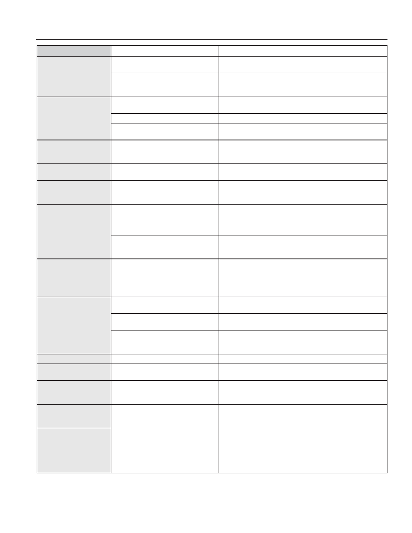
32
49-80773
Problem Possible Cause What To Do
“F— and a number
or letter” flash in the
display
You have a function error code. Press the Cancel/Off pad. Allow the oven to cool for one
hour. Put the oven back into operation.
If the function code repeats. Disconnect all power to the oven for at least 30 seconds and
then reconnect power. If the function error code repeats, call
for service.
Display goes blank A fuse in your home may be blown
or the circuit breaker tripped.
Replace the fuse or reset the circuit breaker.
The clock is turned off. See the Special features section.
Oven is in Sabbath Mode. Verify that the oven is not in Sabbath Mode. See the Special
Features section.
Power outage, clock
flashes
Power outage or surge Reset the clock. If the oven was in use, you must reset it by
pressing the Cancel/Off pad, setting the clock and resetting
any cooking function.
“Burning” or “oily” odor
emitting from the vent
This is normal in a new oven and
will disappear in time.
To speed the process, set a self-clean cycle for a minimum
of 3 hours. See the Cleaning the Oven section.
Strong odor
An odor from the insulation around
the inside of the oven is normal for
the first few times the oven is used.
This is temporary and will go away after several uses or a
self-clean cycle.
Fan noise
(on some models)
A convection fan may automatically
turn on and off.
This is normal. The fan is designed to operate intermittently to
maximize cooking evenness. The convection fan will operate
during preheat of the bake cycle. The fan will turn off after the
oven is heated to the set temperature. This is normal.
A cooling fan may automatically
turn on and off.
This is normal on some models. The cooling fan will turn
off and on to cool internal parts. It may run after the oven is
turned off.
My oven door glass
appears to be "tinted"
or have a "rainbow"
color. Is this defective?
No. The inner oven glass is coated
with a heat barrier to reflect the
heat back into the oven to prevent
heat loss and keep the outer door
cool while baking.
This is normal. Under certain light or angles, you may see
this tint or rainbow color.
Sometimes the oven
takes longer to
preheat to the same
temperature
Cookware or food in oven. The cookware or food in the oven will cause the oven to take
longer to preheat. Remove items to reduce preheat time.
Number of racks in oven. Adding more racks to the oven will cause the oven to take
longer to preheat. Remove some racks.
Different cooking modes. The different cooking modes use different preheat methods
to heat the oven for the specific cooking mode. Some modes
will take longer than others (i.e. Convection Bake).
Display flashes Power failure. Reset the clock.
Unable to get the
display to show “SF”
Oven control pads were not
touched properly.
The Broil Hi/Lo and Bake pads must be touched at the
same time and held for 3 seconds.
Control signals after
entering cooking time
or start time
You forgot to enter a bake
temperature or cleaning time.
Touch the Bake pad and desired temperature or the Self
Clean pad and desired clean time.
Oven racks are difficult
to slide
The shiny, silver-colored racks
were cleaned in a self-clean cycle.
Apply a small amount of vegetable oil to a paper towel and
wipe the edges of the oven racks with the paper towel. Do
not spray with Pam
®
or other lubricant sprays.
Steam from the vent When using the ovens, it is normal
to see steam coming out of the
oven vents. As the number of racks
or amount of food being cooked
increases, the amount of visible
steam will increase.
This is normal.
TROUBLESHOOTING TIPS
Troubleshooting tips (Cont.) ... Before you call for service

Écrivez ici les numéros de modèle et
de série :
No de modèle : _________________
No de série : ____________________
Ces numéros sont indiqués sur la
bordure latérale ou sur le devant du
four (inférieur), derrière la porte du four.
49-80773 08-15 GE
Imprimé aux États-Unis
PCB980 - 76.2 cm (30") Amovible à four double
Manuel d’utilisation
Consignes de sécurité .........2
Garantie .........................7
Assistance/Accessoires .......8
Utilisation de la cuisinière
Éléments de surface ................9
Batterie de cuisine pour table
de cuisson en verre radiant ......12
Commandes du four double .......13
Fonctions spéciales ...............14
Mode Sabbat .....................15
Grilles du four .....................16
Papier d’aluminium et doublures
de four ..........................17
Plats de cuisson ...................17
Modes de cuisson .................18
Guide de cuisson ..................19
Entretien et nettoyage
Nettoyage de la cuisinière
– Extérieur ......................21
Nettoyage de la cuisinière
– Intérieur .......................22
Nettoyage de la table de
cuisson en verre .................23
Entretien ..........................25
Conseils de dépannage .......30
Cuisinières
Cuisinière électrique amovible
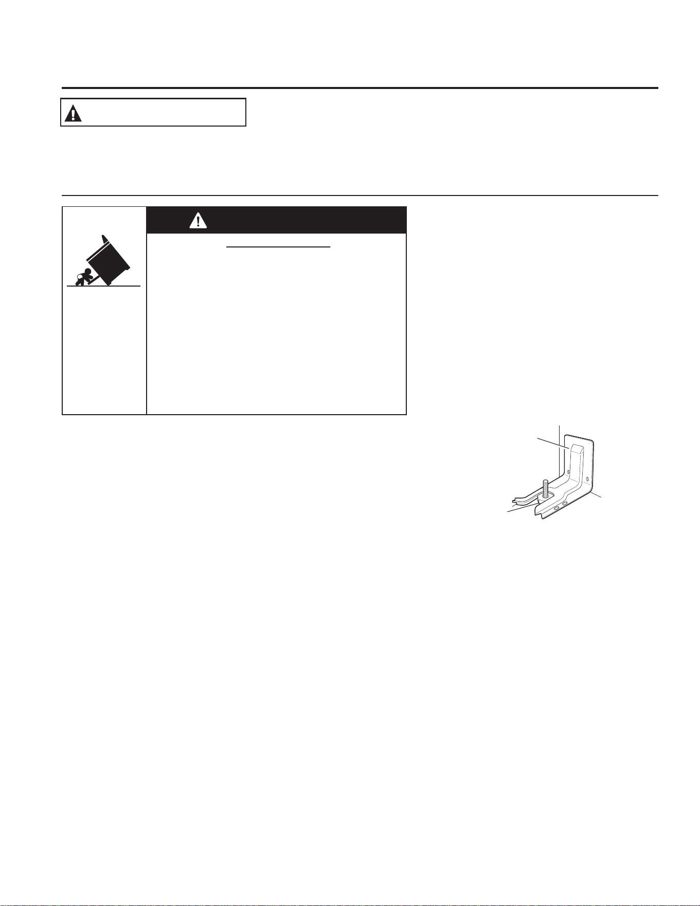
2
49-80773
Veuillez lire toutes les consignes avant d’utiliser ce produit. Le non-respect de ces instructions pourrait entraîner un
incendie, un choc électrique, une blessure grave voire la mort.
DISPOSITIF ANTIBASCULEMENT
AVERTISSEMENT
Pour éviter le basculement accidentel de la
cuisinière, fixez-la en installant de la façon
appropriée le dispositif antibasculement.
Avant de l’installer, consultez les directives
d’installation fournies avec le dispositif.
Pour les cuisinières amovibles ou
encastrées
Pour les cuisinières amovibles ou encastrées
Pour vérifier que le dispositif est installé et
s’enclenche correctement, vérifiez sous la
cuisinière que le pied de mise à niveau arrière
est inséré dans le support. Sur certains
modèles, le tiroir de rangement ou le coup de pied peuvent être
retirés pour faciliter l’inspection. Si l’inspection visuelle n’est pas
possible, faites glisser la cuisinière vers l’avant pour confirmer que
le dispositif antibasculement est solidement fixé au sol ou au mur,
puis faites glisser la cuisinière dans son emplacement de sorte
que le pied de mise à niveau arrière se trouve sous le dispositif
antibasculement.
Si, pour une raison ou une autre, la cuisinière est éloignée
du mur, recommencez toujours cette procédure pour vérifier
que la cuisinière est correctement maintenue par le dispositif
antibasculement.
N’enlevez jamais complètement les pieds de mise à niveau,
la cuisinière ne serait alors pas correctement protégée du
basculement.
Si vous n’avez pas reçu un dispositif antibasculement avec votre
appareil, appelez au 1.800.561.3344 pour en obtenir un sans frais.
Pour obtenir les directives d’installation du dispositif, visitez notre
site Web www.GEAppliances.ca.
Dispositif
antibasculement
Pied de mise à niveau
Cuisinières amovibles ou encastrées
Risque de basculement
AVERTISSEMENT
Un enfant ou un adulte peut faire basculer la cuisinière
et subir des blessures mortelles.
Vérifiez si le dispositif anti-basculement a été correcte-
ment installé et s'il est bien engagé.
Assurez-vous de bien engager de nouveau le pied de la
cui
sinière dans le dispositif anti-basculement après
avoir déplacé la cuisinière.
Ne faites pas fonctionner la cuisinière sans avoir
d'abord vérifié si le dispositif anti-basculement est bien
installé et engagé.
Des adultes ou des enfants pourraient subir des bles-
sures g
raves ou mortelles si les présentes directives ne
sont pas suivies à la lettre.
IMPORTANTES CONSIGNES DE SÉCURITÉ
VEUILLEZ LIRE TOUTES LES INSTRUCTIONS AVANT UTILISATION DU FOUR
CONSIGNES DE SÉCURITÉ
LISEZ ET CONSERVEZ CES INSTRUCTIONS
49-80773
3
Ŷ1¶XWLOLVH]FHWDSSDUHLOTXHSRXUO¶XVDJHSRXUOHTXHOLOD
été conçu, comme expliqué dans le présent manuel.
Ŷ$VVXUH]YRXVTXHYRWUHDSSDUHLOHVWELHQLQVWDOOpHW
mis à la terre par un technicien qualifié, conformément
aux directives d’installation fournies.
Ŷ1HWHQWH]SDVGHUpSDUHUQLGHUHPSODFHUDXFXQH
pièce de votre cuisinière, à moins que cela ne soit
recommandé dans le présent manuel. Toute autre
réparation doit être confiée à un technicien qualifié.
Ŷ$YDQWG¶HIIHFWXHUXQHUpSDUDWLRQGpEUDQFKH]OD
cuisinière ou coupez l’alimentation électrique de
l’appareil en enlevant le fusible ou en déclenchant le
disjoncteur du panneau de distribution électrique.
Ŷ1HODLVVH]SDVOHVHQIDQWVVDQVVXUYHLOODQFH²LO
ne faut jamais laisser les enfants seuls ou sans
surveillance près de l’appareil lorsque celui-ci
fonctionne. On doit également leur interdire de
grimper, de s’asseoir ou de monter sur une partie
quelconque de l’appareil.
Ŷ ATTENTION: Ne rangez pas dans les
armoires se trouvant au-dessus ou sur le dosseret de la
cuisinière des articles qui présentent un intérêt pour les
HQIDQWV²FHX[FLSRXUUDLHQWJULPSHUVXUO¶DSSDUHLOSRXU
les atteindre et risqueraient de se blesser gravement.
Ŷ
N’utilisez que des poignées ou des gants de cuisine
VHFV²OHVSRLJQpHVRXJDQWVGHFXLVLQHKXPLGHVRX
mouillés peuvent causer des brûlures de vapeur. Ne
laissez pas les poignées ou les gants entrer en contact
avec les éléments chauffants ou les surfaces chaudes.
N’utilisez pas de serviettes ou autres objets encombrants
en tissu à la place de poignées ou de gants de cuisine.
Ŷ1¶XWLOLVH]MDPDLVYRWUHDSSDUHLOSRXUFKDXIIHURX
réchauffer la pièce.
Ŷ1HWRXFKH]SDVDX[pOpPHQWVGHVXUIDFHDX[pOpPHQWV
chauffants ou aux parois intérieures du four. Ces
surfaces peuvent être suffisamment chaudes pour
causer des brûlures, même si elles ne sont pas rouges.
Pendant et après leur utilisation, ne touchez pas
aux éléments et évitez que vos vêtements ou autres
matériaux inflammables entrent en contact avec les
éléments de surface, les surfaces autour des éléments
et les parois intérieures du four; laissez-les d’abord
refroidir suffisamment. D’autres surfaces de l’appareil
peuvent devenir suffisamment chaudes pour causer des
brûlures. Il s’agit notamment de la surface de cuisson,
des parties faisant face à la surface de cuisson, de
l’évent du four et les surfaces qui l’entourent, et des
ouvertures autour de la porte du four.
Ŷ1HIDLWHVSDVFKDXIIHUGHFRQWHQDQWVG¶DOLPHQWV
fermés. La pression pourrait s’accumuler et les
contenants pourraient éclater, causant
des blessures.
Ŷ$EVWHQH]YRXVG¶XWLOLVHUWRXWW\SHGHSDSLHURXGH
doublure pour recouvrir le fond ou toute autre partie
du four, sauf indication contraire dans ce manuel. Les
doublures de four peuvent emprisonner la chaleur ou
fondre, endommageant le produit et causant un risque
de choc électrique, d’enfumage ou d’incendie.
ŶeYLWH]G¶pJUDWLJQHUOHVSRUWHVVXUIDFHVGHFXLVVRQRX
tableaux de commande en verre. Ces égratignures ou
impacts peuvent faire casser le verre. N’utilisez pas
un appareil dont une pièce en verre est cassée pour
éviter les risques de choc électrique, d’incendie ou de
coupures.
Ŷ)DLWHVELHQFXLUHODYLDQGHHWODYRODLOOH²ODYLDQGH
jusqu’à une température interne d’au moins 71,1
&)HWODYRODLOOHMXVTX¶jXQHWHPSpUDWXUH
LQWHUQHG¶DXPRLQV&)/DFXLVVRQj
ces températures protège habituellement contre les
maladies d’origine alimentaire.
Ŷ1HUDQJH]SDVRXQ¶XWLOLVH]SDVGHPDWpULDX[
inflammables dans le four ou près de la surface de
cuisson, par exemple du papier, du plastique, des
poignées isolantes, des tissus, du revêtement mural,
des rideaux, des draperies, de l’essence ou toute
autre vapeur ou liquide inflammable.
Ŷ1HSRUWH]MDPDLVGHYrWHPHQWVDPSOHVORUVTXHYRXV
utilisez cet appareil. Ils pourraient prendre feu au contact
d’une surface brûlante, causant de graves brûlures.
Ŷ1HODLVVH]SDVGHJUDLVVHVGHFXLVVRQRXDXWUHV
substances inflammables s’accumuler à l’intérieur ou à
proximité de la cuisinière. La graisse dans le four ou
sur la surface de cuisson pourrait prendre feu.
Ŷ1HWWR\H]UpJXOLqUHPHQWODKRWWHGHFXLVLQH,OQHIDXW
pas laisser de graisses s’accumuler sur la hotte ou le
filtre.
CONSIGNES DE SÉCURITÉ GÉNÉRALES
TENEZ LES MATÉRIAUX ET SUBSTANCES INFLAMMABLES À
L’ÉCART DE LA CUISINIÈRE
AVERTISSEMENT
AVERTISSEMENT
Le non-respect de ces instructions pourrait entraîner un incendie ou une blessure.
CONSIGNES DE SÉCURITÉ
LISEZ ET CONSERVEZ CES INSTRUCTIONS
4
49-80773
IMPORTANTES CONSIGNES DE SÉCURITÉ
VEUILLEZ LIRE TOUTES LES INSTRUCTIONS AVANT UTILISATION DU FOUR
CONSIGNES DE SÉCURITÉ
Ŷ Ne tentez pas d’éteindre des feux de graisse avec
de l’eau. Ne prenez jamais une casserole enflammée
GDQVYRVPDLQV5DPHQH]OHVFRPPDQGHVj2))
$UUrWeWHLJQH]OHVIODPPHVVXUODVXUIDFHGH
cuisson à l’aide d’un couvercle hermétique, d’une
plaque à biscuits ou d’un plateau. Utilisez un
extincteur chimique tous usages à poudre sèche ou à
mousse.
Ŷ Si un aliment prend feu dans le four pendant la
cuisson, éteignez les flammes en fermant la porte
et en éteignant le four, ou en utilisant un extincteur
chimique tous usages à poudre sèche ou à mousse.
Ŷ6LXQIHXpFODWHGDQVOHIRXUSHQGDQWO¶DXWRQHWWR\DJH
éteignez le four et attendez que le feu s’éteigne.
N’ouvrez pas la porte de force. L’introduction d’air
IUDLVGDQVOHIRXUDX[WHPSpUDWXUHVG¶DXWRQHWWR\DJH
pourrait provoquer l’apparition de flammes. Le non-
respect de cette consigne pourrait causer de graves
brûlures.
Ŷ Ne laissez jamais les éléments de surface sans
surveillance lorsqu’ils sont réglés à une température
PR\HQQHRXpOHYpH/HVDOLPHQWVUHQYHUVpVSHXYHQW
causer de la fumée, tandis que la graisse peut
prendre feu.
Ŷ 1HODLVVH]SDVO¶KXLOHVDQVVXUYHLOODQFHSHQGDQWOD
friture. Si elle dépasse son point de fumée, l’huile
pourrait prendre feu, causant un incendie qui pourrait
se propager aux armoires environnantes. Si possible,
utilisez un thermomètre de friture pour surveiller la
température de l’huile.
Ŷ 3RXUpYLWHUOHVGpERUGHPHQWVG¶KXLOHHWOHVLQFHQGLHV
utilisez une quantité minimale d’huile lorsque vous
faites frire des aliments dans une casserole peu
profonde et évitez de faire cuire des aliments surgelés
présentant une quantité excessive de glace.
Ŷ 8WLOLVH]GHVXVWHQVLOHVGHFXLVVRQGHODGLPHQVLRQ
DSSURSULpH²FKRLVLVVH]GHVXVWHQVLOHVjIRQGSODW
suffisamment grands pour couvrir l’élément de
surface. L’utilisation d’ustensiles trop petits exposent
une partie de l’élément de surface à des contacts
directs, ce qui pourrait mettre le feu aux vêtements.
L’utilisation d’un ustensile approprié à l’élément de
surface améliore également l’efficacité.
Ŷ 6HXOVFHUWDLQVW\SHVGHYHUUHGHYLWURFpUDPLTXHGH
terre cuite ou autres contenants émaillés conviennent
à la cuisson sur la surface de cuisson; les autres
peuvent se briser à cause du changement soudain de
température.
Ŷ 3RXUUpGXLUHDXPLQLPXPOHVULVTXHVGHEUOXUHV
d’incendie ou de renversements, assurez-vous de
tourner la poignée des ustensiles vers le centre de
la cuisinière, en évitant de la placer au-dessus des
éléments de surface adjacents.
Ŷ /RUVTXHYRXVIDLWHVIODPEHUGHVDOLPHQWVVRXVOD
hotte, mettez le ventilateur en marche.
Ŷ (QFDVGHFRXSXUHG¶pOHFWULFLWpG¶XQHFXLVLQLqUH
électrique alors que la surface de cuisson est
allumée, cette surface de cuisson se rallumera
lorsque l’alimentation électrique est rétablie. En cas
de coupure d’électricité, si vous ne tournez pas les
ERXWRQVGHFRPPDQGHVXUODSRVLWLRQ2))FHUWDLQV
objets sur la surface de cuisson ou à proximité de
celle-ci pourraient s’enflammer et provoquer de
graves blessures voire la mort.
EN CAS D’INCENDIE, PRENEZ LES MESURES SUIVANTES POUR
PRÉVENIR LES BLESSURES ET LA PROPAGATION DU FEU
CONSEILS DE SÉCURITÉ CONCERNANT LA SURFACE
DE CUISSON
AVERTISSEMENT
AVERTISSEMENT
LISEZ ET CONSERVEZ CES INSTRUCTIONS
49-80773
5
CONSIGNES DE SÉCURITÉ
Ŷ6R\H]SUXGHQWORUVTXHYRXVWRXFKH]jODVXUIDFHGH
cuisson. La surface en verre demeure très chaude
DSUqVTXHYRXVD\H]pWHLQWOHVpOpPHQWV
Ŷ N’utilisez pas la surface de cuisson si le verre est
brisé. Des éclaboussures d’aliments ou du liquide
GHQHWWR\DJHSRXUUDLHQWV¶LQILOWUHUGDQVODVXUIDFH
de cuisson et créer un risque de choc électrique.
Communiquez immédiatement avec un technicien
qualifié.
ŶeYLWH]G¶pJUDWLJQHUODVXUIDFHGHFXLVVRQHQYHUUH/D
surface peut être égratignée par des objets comme
des instruments pointus, des bagues et autres bijoux,
et les rivets des vêtements.
Ŷ Ne posez pas et ne rangez pas d’objets susceptibles
de fondre ou de prendre feu sur la surface de cuisson
en verre, même lorsqu’elle n’est pas utilisée. Si vous
allumez par inadvertance un élément de surface, ces
objets pourraient prendre feu. De plus, ces objets
pourraient prendre feu sous l’effet de la chaleur
produite par l’évent du four ou la surface de cuisson
après que les éléments ont été éteints.
Ŷ8WLOLVH]ODFUqPHQHWWR\DQWHSRXUVXUIDFHGHFXLVVRQ
en vitrocéramique CERAMA BRYTEMD et le tampon
GHQHWWR\DJH&(5$0$%5<7(0'SRXUQHWWR\HU
la surface de cuisson. Attendez que la surface de
FXLVVRQDLWUHIURLGLHWTXHOHYR\DQWGHVXUIDFHFKDXGH
VHVRLWpWHLQWDYDQWGHFRPPHQFHUOHQHWWR\DJH
L’utilisation d’une éponge ou d’un chiffon humide
sur une surface brûlante peut causer des brûlures
jFDXVHGHODYDSHXU&HUWDLQVSURGXLWVQHWWR\DQWV
peuvent dégager des vapeurs nocives lorsqu’ils sont
appliqués sur une surface chaude.
REMARQUE : Les aliments sucrés renversés sont
l’exception à la règle. Il faut les enlever à l’aide
d’un grattoir et d’un gant de cuisine pendant qu’ils
sont encore chauds. Pour des directives détaillées,
UHSRUWH]YRXVjODVHFWLRQ1HWWR\DJHGHODVXUIDFHGH
cuisson en verre.
Ŷ Veuillez lire et suivre toutes les directives et mises en
JDUGHVXUO¶pWLTXHWWHGHODFUqPHQHWWR\DQWH
ŶeORLJQH]YRXVGHODFXLVLQLqUHORUVTXHYRXVRXYUH]
la porte du four. L’air chaud ou la vapeur qui s’en
échappe pourrait vous causer des brûlures aux mains,
DXYLVDJHHWRXDX[\HX[
Ŷ 1XWLOLVH]SDVOHIRXUVLXQH]RQHGHOpOpPHQW
chauffant devient incandescente pendant son
XWLOLVDWLRQRXVLGDXWUHVVLJQHVGHQGRPPDJHPHQW
sont visibles. Une zone incandescente indique que
OpOpPHQWSHXWGpIDLOOLUHWSUpVHQWHUXQULVTXHGH
EUOXUHGLQFHQGLHRXGHFKRFpOHFWULTXHeWHLJQH]
OHIRXULPPpGLDWHPHQWHWIDLWHVUHPSODFHUOpOpPHQW
chauffant par un technicien agréé.
Ŷ $VVXUH]YRXVTXHO¶pYHQWGXIRXUQ¶HVWSDVREVWUXp
Ŷ eYLWH]O¶DFFXPXODWLRQGHJUDLVVHGDQVOHIRXU(OOH
pourrait prendre feu.
Ŷ 3ODFH]OHVJULOOHVGXIRXUjODKDXWHXUGpVLUpHSHQGDQW
que le four est froid. Si vous devez manipuler les
grilles lorsqu’elles sont chaudes, évitez que les
poignées ou les gants de cuisine entrent en contact
avec les éléments chauffants du four.
Ŷ 6LYRXVXWLOLVH]GHVVDFVGHFXLVVRQRXGHU{WLVVDJH
dans le four, suivez les directives du fabricant.
Ŷ 7LUH]ODJULOOHGXIRXUMXVTX¶jODEXWpHSRXUVRXOHYHU
les ustensiles de cuisson lourds. Vous éviterez ainsi
de vous brûler en touchant aux surfaces chaudes de
la porte et aux parois du four.
Ŷ 1HUDQJH]SDVGDQVOHIRXUGHVDUWLFOHVFRPPHGHV
produits en papier, des ustensiles de cuisson ou des
aliments pendant qu’il n’est pas utilisé. Les articles
rangés dans le four pourraient prendre feu.
Ŷ 1HSODFH]MDPDLVG¶XVWHQVLOHVGHSLHUUHVjSL]]DRX
GHFXLVVRQQLWRXWW\SHGHSDSLHURXGHGRXEOXUHVXU
le fond du four. Ces articles peuvent emprisonner
la chaleur ou fondre, endommageant le produit et
causant un risque de choc électrique, d’enfumage ou
d’incendie.
CONSIGNES DE SÉCURITÉ CONCERNANT LES
ÉLÉMENTS RADIANTS
CONSEILS DE SÉCURITÉ CONCERNANT LE FOUR
AVERTISSEMENT
AVERTISSEMENT
LISEZ ET CONSERVEZ CES INSTRUCTIONS

6
49-80773
IMPORTANTES CONSIGNES DE SÉCURITÉ
VEUILLEZ LIRE TOUTES LES INSTRUCTIONS AVANT UTILISATION DU FOUR
CONSIGNES DE SÉCURITÉ
/DIRQFWLRQG¶DXWRQHWWR\DJHIDLWIRQFWLRQQHUOHIRXUjGHVWHPSpUDWXUHVVXIILVDPPHQWpOHYpHVSRXUEUOHUOHVUpVLGXVGHQRXUULWXUH
dans le four. Suivez ces instructions pour une utilisation en toute sécurité.
Ŷ Ne touchez pas les surfaces du four durant le
IRQFWLRQQHPHQWGHO¶DXWRQHWWR\DJHeORLJQH]OHVHQIDQWV
GXIRXUGXUDQWO¶DXWRQHWWR\DJH/HQRQUHVSHFWGHFHV
instructions pourrait entraîner des blessures.
Ŷ $YDQWGHODQFHUOHF\FOHGDXWRQHWWR\DJHUHWLUH]OHV
casseroles, les grilles de four en métal brillant et les autres
ustensiles du four. Seuls les grilles de four enduits de
SRUFHODLQHJULVHSHXYHQW\rWUHODLVVpHV1XWLOLVH]SDV
ODXWRQHWWR\DJHSRXUQHWWR\HUGDXWUHVDUWLFOHVWHOVTXH
lèchefrites ou bols.
Ŷ $YDQWGHPHWWUHHQPDUFKHO¶DXWRQHWWR\DJHHQOHYH]OD
graisse et les résidus de nourriture du four. Une trop grande
quantité de graisse pourrait s’enflammer, et la fumée
pourrait causer des dommages à votre résidence.
Ŷ 6LOHPRGHG¶DXWRQHWWR\DJHIRQFWLRQQHPDOpWHLJQH]OHIRXU
HWGpEUDQFKH]O¶DOLPHQWDWLRQ)DLWHVDSSHOjXQWHFKQLFLHQ
qualifié pour l’entretien.
Ŷ 1HQHWWR\H]SDVOHMRLQWGHODSRUWH&HOXLFLHVWHVVHQWLHOj
O¶pWDQFKpLWp)DLWHVDWWHQWLRQjQHSDVIURWWHUHQGRPPDJHU
ni déplacer le joint.
Ŷ 1¶XWLOLVH]SDVGHSURGXLWVQHWWR\DQWVjIRXU$XFXQSURGXLW
QHWWR\DQWjIRXUSURIHVVLRQQHOQLGHUHYrWHPHQWSURWHFWHXU
de four ne doivent être utilisés à l’intérieur du four ou sur
tout autre partie de celui-ci.
INSTRUCTIONS POUR L’AUTONETTOYAGE DU FOUR
AVERTISSEMENT
&HWDSSDUHLOHVWFRQIRUPHDYHF,QGXVWULH&DQDGD566VWDQGDUGH[HPSWVGHOLFHQFHV6RQXWLOLVDWLRQHVWVRXPLVHj/HVGHX[
conditions suivantes:
1. cet appareil ne peut pas provoquer d’interférences et
FHWDSSDUHLOGRLWDFFHSWHU7RXWHLQWHUIpUHQFH\FRPSULVOHVLQWHUIpUHQFHVTXLSHXYHQWFDXVHUXQPDXYDLVIRQFWLRQQHPHQWGX
dispositive.
&HWDSSDUHLOHVWFRQIRUPHDX[H[LJHQFHVGHOD)&&HWGHO¶,&HQPDWLqUHG¶H[SRVLWLRQDX[5)GDQVOHVHQYLURQQHPHQWVSXEOLFVRX
QRQFRQWU{OpV
L’antenne utilisée pour cet émetteur doit être installé de façon à mettre une distance d’au moins 20 cm avec toute personne.
LISEZ ET CONSERVEZ CES INSTRUCTIONS

49-80773
7
Merci ... d’avoir acheté un appareil GE !
Garantie sur la cuisinière électrique.
GEAppliances.ca
Tout entretien ou réparation en vertu de la garantie est fourni par nos Centres d’entretien et de réparation de l’usine ou par un
technicien autorisé de Customer Care®. Pour fixer un rendez-vous en ligne, consultez notre site www.GEAppliances.ca ou
téléphonez au 1.800.561.3344. Veuillez avoir vos numéros de série et de modèle à portée de main lors de l’appel.
L’entretien de votre appareil pourrait nécessiter l’utilisation d’un accès aux données embarquées pour le diagnostic. Cet accès
donne au technicien la capacité de diagnostiquer rapidement tout problème avec votre appareil et d’aider Mabe à améliorer ses
produits en fournissant à cette dernière des renseignements sur votre appareil. Si vous ne souhaitez pas que les données de votre
DSSDUHLOVRLHQWHQYR\pHVj0DEHYHXLOOH]HQDYLVHUYRWUHWHFKQLFLHQDXPRPHQWGHO¶HQWUHWLHQ
La garantie limitée sera valide pour la période d’un an suivant la date de l’achat original. En cas de défaillance de la cuisinière dûe
à un défaut des matériaux ou de la main d’œuvre, Mabe fournira, sans frais, toute la main d’œuvre nécessaire à domicile pour
remplacer la pièce défectueuse.
Ce que Mabe ne couvre pas :
Ŷ /¶HQYRLG¶XQWHFKQLFLHQFKH]YRXVSRXUYRXVPRQWUHU
comment utiliser le produit.
Ŷ 8QHLQVWDOODWLRQXQHOLYUDLVRQRXXQHQWUHWLHQLQDGpTXDWV
Ŷ 8QHSDQQHGXSURGXLWVXLWHjXQHXWLOLVDWLRQDEXVLYHRX
inadéquate, une modification, un usage autre que celui
auquel il a été destiné ou un usage commercial.
Ŷ /HVGRPPDJHVFDXVpVjODVXUIDFHGHFXLVVRQHQYHUUHSDU
O¶XWLOLVDWLRQGHSURGXLWVQHWWR\DQWVDXWUHVTXHOHQHWWR\DQWHW
les tampons recommandés.
Ŷ /HVGRPPDJHVFDXVpVjODVXUIDFHGHFXLVVRQHQYHUUH
par des éclaboussures de produits sucrés durcis ou du
SODVWLTXHIRQGXTXLQ¶RQWSDVpWpQHWWR\pVFRQIRUPpPHQW
aux directives données dans le manuel d’utilisation.
Ŷ /HUHPSODFHPHQWGHVIXVLEOHVGHYRWUHUpVLGHQFHRXOH
réenclenchement des disjoncteurs.
Ŷ /HVGRPPDJHVDXSURGXLWFDXVpVSDUXQDFFLGHQWXQ
incendie, une inondation ou une catastrophe naturelle.
Ŷ /HVGRPPDJHVLQGLUHFWVRXDFFLGHQWHOVFDXVpVSDUGHV
défaillances possibles de cet appareil.
Ŷ /HVGRPPDJHVRFFDVLRQpVDSUqVODOLYUDLVRQ
Ŷ /HVHUYLFHG¶LOHVWLPSRVVLEOHGªDYRLUDFFqVDXSURGXLW
Ŷ /HVHUYLFHSRXUUpSDUHURXUHPSODFHUOHVDPSRXOHVj
l’exception des lampes DEL.
EXCLUSION DES GARANTIES IMPLICITES
Votre seul et unique recours est la réparation du produit selon les dispositions de la présente garantie limitée. Toutes garanties
LPSOLFLWHV\FRPSULVOHVJDUDQWLHVLPSOLFLWHVGHTXDOLWpPDUFKDQGHHWG¶DGpTXDWLRQjXQXVDJHVSpFLILTXHVRQWOLPLWpHVjXQDQRX
à la plus courte période permise par la loi.
Cette garantie s’étend à l’acheteur original et à tout propriétaire ultérieur pour les produits achetés au Canada destinés à un usage
en résidence se trouvant au Canada. L’entretien à domicile prévu par la garantie sera proposé dans les lieux où il est disponible et
où Mabe juge raisonnable de le fournir.
Certaines provinces ne permettent pas l’exclusion ni la limitation des dommages indirects. La présente garantie vous accorde
des droits juridiques spécifiques, et vous disposez également de droits supplémentaires qui varient d’une province à l’autre. Pour
connaître vos droits selon votre province, consultez votre bureau local d’information au consommateur.
Garant : Mabe Canada Inc., Burlington, Ontario
Enregistrez votre appareil : Enregistrez votre nouvel appareil en ligne à tout moment.
www.geappliances.ca/register/index.jsp
Si vous enregistrez votre produit sans délai, la communication sera meilleure et le service plus rapide en vertu des conditions de votre
JDUDQWLHVLVRQXWLOLVDWLRQV¶DYqUHQpFHVVDLUH9RXVSRXYH]pJDOHPHQWHQYR\HUSDUODSRVWHODFDUWHG¶HQUHJLVWUHPHQWSUpLPSULPpH
incluse dans les matériaux d’emballage.
Agrafez ici votre reçu. Une preuve de l’achat original est requise
pour l’accès à l‘entretien et aux réparations en vertu de la garantie.
GARANTIE

8
49-80773
Rendez-vous pour l’entretien : Le service de réparation
par un expert de GE ne se trouve qu’à un pas de votre porte.
Connectez-vous à Internet et fixez votre rendez-vous sur
www.GEAppliances.ca ou appelez le 1.800.561.3344 pendant
les heures de bureau.
Pièces et accessoires : Les personnes qualifiées pour
entretenir leur propre appareil peuvent recevoir des pièces
ou des accessoires directement chez eux (les cartes Visa,
0DVWHU&DUGHW'LVFRYHUVRQWDFFHSWpHV&RPPDQGH]HQ
ligne dès aujourd’hui, 24 heures sur 24, ou appelez au
1.800.661.1616 pendant les heures de bureau.
Les instructions qui se trouvent dans le présent manuel
couvrent les procédures devant être effectuées par n’importe
quel utilisateur. L’entretien et les réparations qui ne se trouvent
pas ici doivent généralement être confiés à du personnel
qualifié. Il est nécessaire de faire preuve de prudence, car un
entretien inapproprié pourrait entraîner une utilisation non-
sécuritaire de l’appareil.
Contactez-nous : Si vous n’êtes pas satisfait du service que vous
UHFHYH]GH*(FRQWDFWH]QRXVDXPR\HQGHQRWUHVLWHLQWHUQHW
HQQRXVIRXUQLVVDQWWRXVOHVGpWDLOVQpFHVVDLUHV\FRPSULVYRWUH
numéro de téléphone, ou écrivez à :
Director, Customer Relation, Mabe Canada Inc.
Suite 310, 1 Factory Lane
Moncton, N.B. E1C9M33
ASSISTANCE/ACCESSOIRES
Consultez le site internet des appareils GE (www.geappliances.ca/customer/appservice.jspKHXUHVVXUMRXUVVXU
Pour une plus grande commodité et pour un service plus rapide, vous pouvez maintenant télécharger les manuels d’utilisation,
commander certaines pièces et même fixer un rendez-vous pour l’entretien en ligne.
Vous avez une question ou vous avez besoin d’assistance avec votre appareil ?
Accessoires
À la recherche d’un accessoire?
GE propose une variété d’accessoires pour améliorer vos expériences de cuisine et entretien!
Pour passer commande, consultez notre site internet à l’adresse suivante :
www.GEAppliances.ca
800.661.1616 Centre national de pièces (Canada)
Les produits suivants sont notamment disponibles :
Comment retirer le film protecteur d’expédition et le ruban adhésif d’emballage
Saisissez délicatement un coin du film protecteur d’expédition
avec vos doigts et le décoller lentement de la surface de
l’appareil. N’utilisez pas d’objets pointus pour retirer le film.
Retirez complètement le film avant d’utiliser l’appareil pour la
première fois.
Pour assurer ne pas endommager la finition du produit, la façon
la plus sûre pour enlever le ruban adhésif de l’emballage sur les
nouveaux appareils consiste à appliquer un détergent à vaisselle
liquide à l’aide d’un chiffon doux et à laisser tremper.
REMARQUE : Le ruban adhésif doit être retiré de toutes les
pièces. Il ne pourra pas être retiré après cuisson.
Accessoires
3HWLWHOqFKHIULWHFP[FP[FPôSR[óSR[òSR '*&DQDGD
/DJUDQGHOqFKHIULWHFP[FP[FPôSR[óSR[òSR '*&DQDGD
Pièces
Grilles de four Les numéros de pièces varient selon le modèle.
eOpPHQWVGXIRXU /HVQXPpURVGHSLqFHVYDULHQWVHORQOHPRGqOH
Ampoules Les numéros de pièces varient selon le modèle.
Matériel de nettoyage
/LQJHWWHVSRXUDFLHULQR[\GDEOH&LWUX6KLQH :;;
3URGXLWQHWWR\DQWSRXUDSSDUHLOHQDFLHULQR[\GDEOH&(5$0$%5<7(
®
30;
CERAMA BRYTE
®
7DPSRQVSRXUVXUIDFHGHFXLVVRQHQYLWURFpUDPLTXH :;;
CERAMA BRYTE
®
1HWWR\DQWSRXUVXUIDFHGHFXLVVRQHQYLWURFpUDPLTXH :;;
CERAMA BRYTE
®
*UDWWRLUSRXUVXUIDFHGHFXLVVRQHQYLWURFpUDPLTXH :;;
(QVHPEOHOHQVHPEOHFRPSUHQGODFUqPHQHWWR\DQWHHWOHJUDWWRLU :%;
*La grande lèchefrite est trop grande pour les cuisinières de 20po/24po.
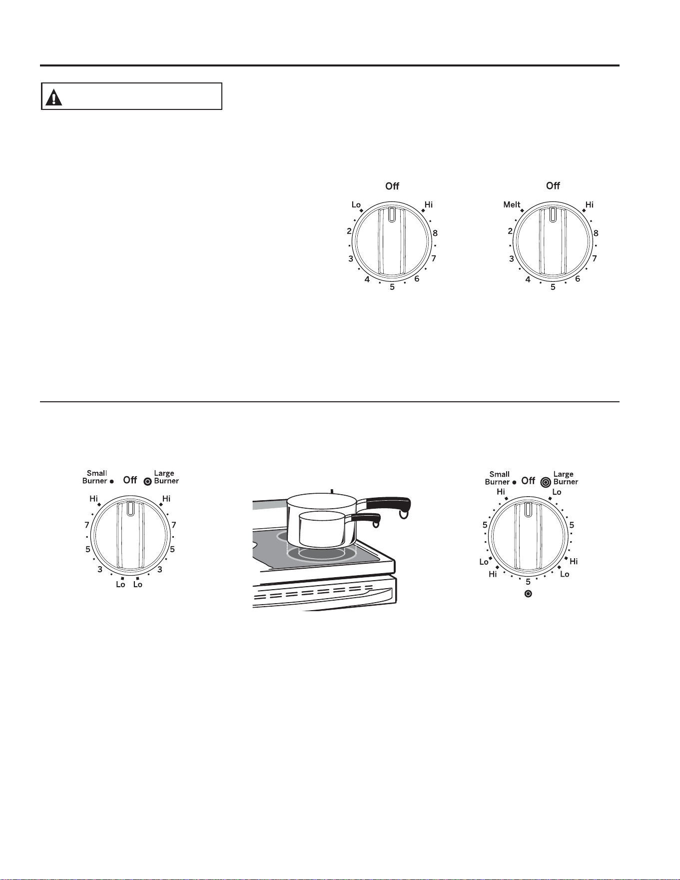
49-80773
9
UTILISATION DE LA CUISINIÈRE : Éléments de surface
Éléments de surface
RISQUE D’INCENDIE : Ne laissez jamais la cuisinière sans surveillance lorsque des
pOpPHQWVGHODVXUIDFHGHFXLVVRQVRQWUpJOpVjXQHWHPSpUDWXUHPR\HQQHRXpOHYpH
Tenez les articles inflammables à l’écart de la surface de cuisson. Lorsque la cuisson
HVWWHUPLQpHUDPHQH]WRXWHVOHVFRPPDQGHVj2))$UUrW/HQRQUHVSHFWGHFHV
consignes pourrait causer un incendie ou des blessures graves ou mortelles.
AVERTISSEMENT
Dans le présent manuel, les caractéristiques et leur apparence peuvent être différentes de celles de votre modèle.
Réglage
$SSX\H]VXUOHERXWRQHWWRXUQH]OHGDQVXQVHQVRXGDQV
l’autre jusqu’au réglage désiré.
Un témoin lumineux indiquant que la surface de cuisson est
allumée sera allumé lorsqu’un élément de cuisson est allumé.
Surfaces de cuisson en verre :
Un témoin lumineux HOT COOKTOP (Table de cuisson
WUqVFKDXGH
Ŷ V¶DOOXPHORUVTXHO¶pOpPHQWUHVWHFKDXGDXWRXFKHU
Ŷ UHVWHDOOXPpPrPHDSUqVTXHO¶pOpPHQWVRLWpWHLQW
Ŷ UHVWHDOOXPpMXVTX¶jFHTXHO¶pOpPHQWVHVRLWUHIURLGLj
HQYLURQ&)
Éléments de surface doubles et triples et boutons de commande (sur certains modèles)
L’élément de surface offre deux ou trois zones de cuisson, selon l’ustensile de cuisson que vous utilisez.
Aux positions OFF (Arrêt) et HI (Max.),
la commande fait entendre un déclic.
Pendant la cuisson, il est possible que vous
entendiez de légers déclics. Ils indiquent
que la commande maintient le niveau de
puissance que vous avez choisi.
Assurez-vous de ramener la commande à
OFF lorsque la cuisson est terminée.
Modèles avec uniquement un
éléme nt surface double
Modèles avec uniquement un
élément surface triple
Le réglage Melt (Fondre), sur
certains modèles permet de faire
fondre du chocolat ou du beurre.
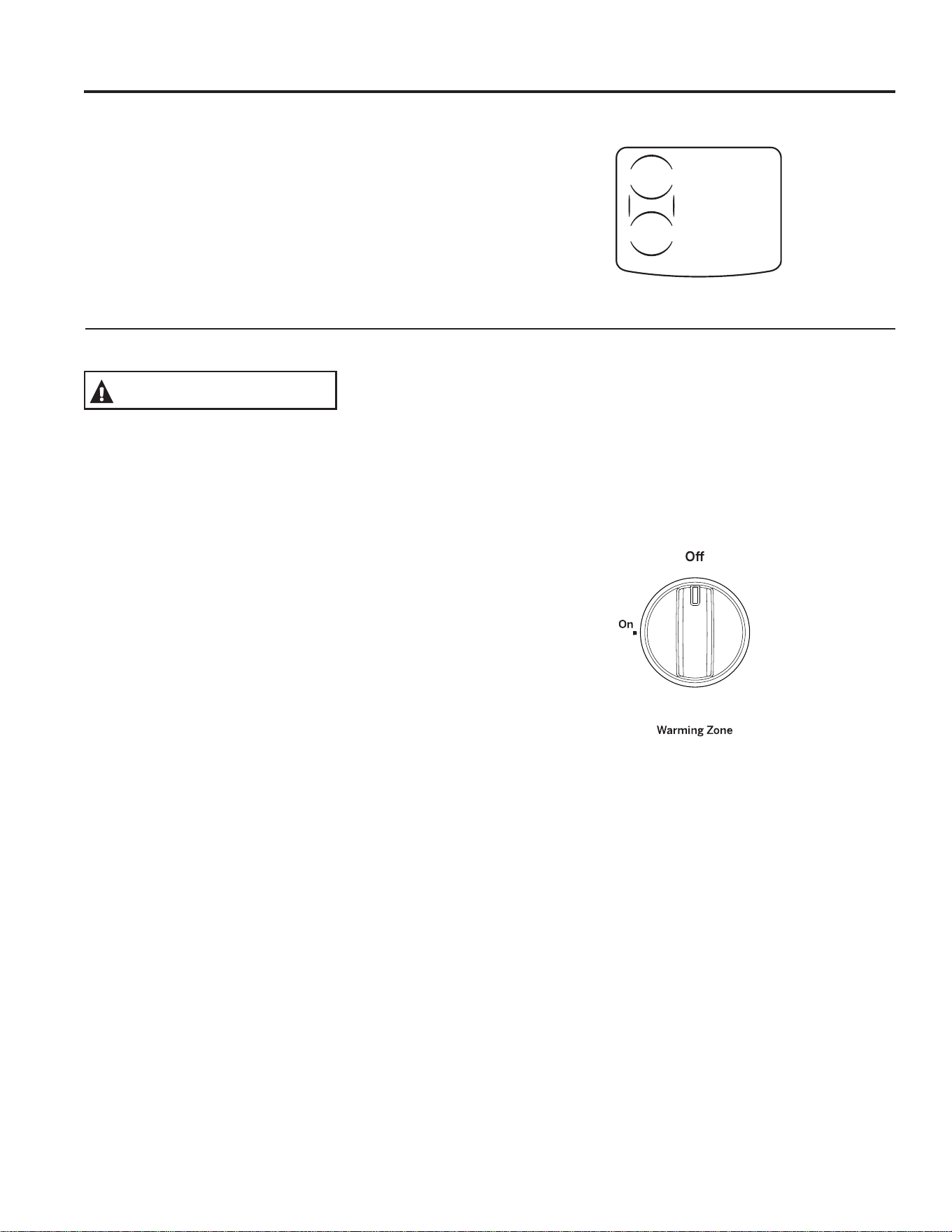
10
49-80773
Éléments de surface (suite)
UTILISATION DE LA CUISINIÈRE : Éléments de surface
Dans le présent manuel, les caractéristiques et leur apparence peuvent être différentes de celles de votre modèle.
Utilisation de la zone de pont (sur certains modèles)
Pour utiliser la zone de pont, réglez les boutons de commande
pour les éléments arrière gauche et avant gauche afin de créer
une seule grande zone permettant une cuisson uniforme.
Utilisation de la Warming Zone (Zone de maintien au chaud)
RISQUE D’INTOXICATION ALIMENTAIRE : Les bactéries
peuvent se développer dans les aliments à des températures
LQIpULHXUHVj&)
Ŷ 8WLOLVH]XQLTXHPHQWGHVDOLPHQWVGpMjFKDXGV&HWWH
fonction ne doit pas être utilisée pour réchauffer des
aliments froids.
Ŷ &HWWHIRQFWLRQQHGRLWSDVrWUHXWLOLVpHSHQGDQWSOXVGH
heures.
La Warming Zone (Zone de maintien au chaud) est située
à l’arrière au centre de la surface de cuisson et conserve les
aliments chauds et cuits à la température de service. Utilisez
uniquement des aliments déjà chauds. Ne l’utilisez pas pour
réchauffer des aliments froids. Si vous placez des aliments
froids ou crus sur Warming Zone (Zone de maintien au
chaud) vous risquez une intoxication alimentaire.
7RXUQH]OHERXWRQGHFRPPDQGHjODSRVLWLRQ210DUFKH
Pour de meilleurs résultats, tous les aliments placés sur la
Warming Zone (Zone de maintien au chaud) doivent être
couverts à l’aide d’un couvercle ou d’une feuille d’aluminium.
/DWHPSpUDWXUHLQLWLDOHOHW\SHHWODTXDQWLWpGHQRXUULWXUHOH
W\SHGHOqFKHIULWHHWOHWHPSVGHUpVLGHQFHDXURQWXQLPSDFW
sur la qualité de la nourriture.
Utilisez toujours des poignées ou de gants de cuisine lorsque
vous retirez des aliments de la Warming Zone (Zone de
maintien au chaud) car le récipient ou les assiettes seront
chauds.
REMARQUE : L’élément de maintien au chaud ne deviendra
pas rouge comme les éléments de cuisson.
Modèles munis d'une zone de pont seulement
AVERTISSEMENT
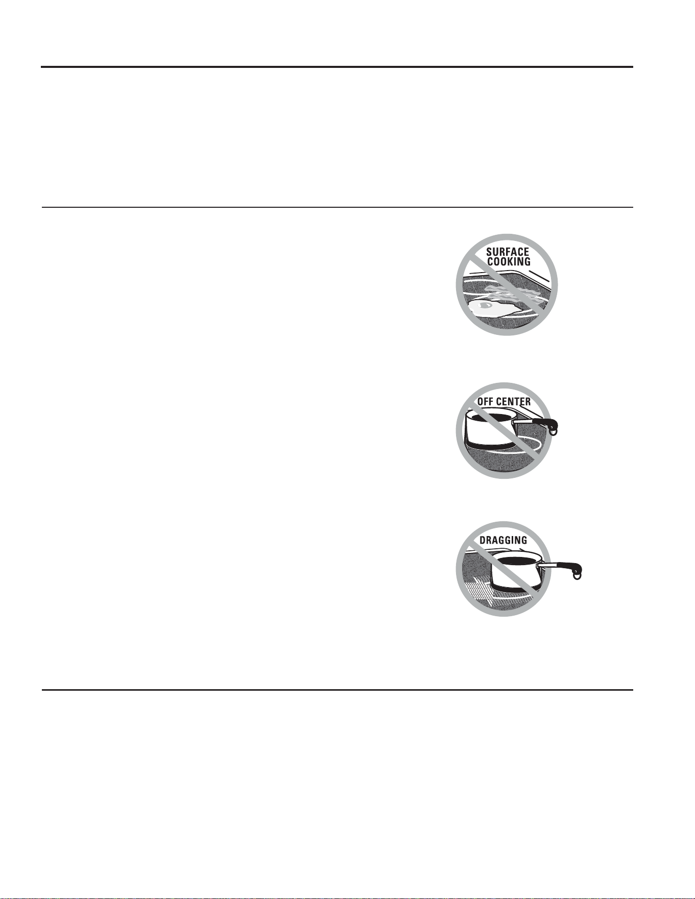
49-80773
11
Conseils pour la mise en conserve
Placez le cuiseur sous pression au centre de l’élément de
surface.
Assurez-vous que son fond est plat.
Pour éviter les brûlures causées par la vapeur ou la chaleur,
VR\H]SUXGHQWORUVTXHYRXVIDLWHVGHVFRQVHUYHV
Suivez des recettes et des procédures de sources fiables.
Vous pouvez vous les procurer auprès de fabricants comme
Ball
®
et Kerr
®
, ainsi que du ministère de l’Agriculture.
Les cuiseurs à pression à fond plat sont recommandés.
Les bains-marie à fond ondulé peuvent allonger le temps
nécessaire pour que l’eau atteigne le point d’ébullition.
Limiteur de température des éléments de surface radiants en verre
Chacun des éléments de surface radiants est doté d’un limiteur
de température.
Ce dispositif protège la surface de cuisson en verre contre les
températures excessives.
Le limiteur de température peut éteindre l’élément de façon
F\FOLTXHSHQGDQWXQFHUWDLQWHPSVORUVTXH
Ŷ O¶XVWHQVLOHFKDXIIHjYLGH
Ŷ OHIRQGGHO¶XVWHQVLOHQ¶HVWSDVSODW
Ŷ O¶XVWHQVLOHQ¶HVWSDVDXFHQWUHGHO¶pOpPHQW
Ŷ DXFXQXVWHQVLOHQ¶HVWSODFpVXUO¶pOpPHQW
Pour les modèles avec une surface de cuisson radiante en verre
La surface de cuisson radiante est dotée d’éléments chauffants
situés sous la surface de cuisson en verre.
REMARQUE : Il est normal de sentir une légère odeur lorsque
la surface de cuisson neuve est utilisée pour la première
fois. Cette odeur est attribuable aux nouvelles pièces et aux
matériaux isolants qui chauffent et disparaîtra rapidement.
REMARQUE : Sur les modèles dont le verre de la surface
de cuisson est de couleur claire, il est normal que les zones
de cuisson changent de couleur lorsqu’elles sont chaudes
ou qu’elles refroidissent. Ce changement est temporaire et
disparaît à mesure que le verre refroidit pour revenir à la
température ambiante.
L’élément s’allume et s’éteint continuellement pour maintenir le
niveau de chaleur choisi.
Vous pouvez sans danger placer des ustensiles de cuisson
brûlants, sortant du four ou provenant d’un autre élément de
surface, sur la surface de verre froide.
Même après avoir éteint les éléments de surface, la surface
de cuisson en verre demeure suffisamment chaude pour
poursuivre la cuisson. Pour éviter une cuisson excessive,
UHWLUH]O¶XVWHQVLOHGHO¶pOpPHQWORUVTXHO¶DOLPHQWHVWFXLWeYLWH]
de placer sur l’élément un autre ustensile de cuisson avant que
l’élément ait totalement refroidi
Ŷ 9RXVSRXYH]IDLUHGLVSDUDvWUHOHVWDFKHVG¶HDXGpS{WVGH
PLQpUDX[jO¶DLGHGHODFUqPHQHWWR\DQWHRXGHYLQDLJUH
blanc non dilué.
Ŷ /¶XWLOLVDWLRQG¶XQSURGXLWQHWWR\DQWSRXUOHVYLWUHVSHXWODLVVHU
XQHSHOOLFXOHFKDWR\DQWHVXUODVXUIDFHGHFXLVVRQ/D
FUqPHQHWWR\DQWHIHUDGLVSDUDvWUHFHWWHGpFRORUDWLRQ
Ŷ 1HUDQJH]SDVG¶DUWLFOHVORXUGVDXGHVVXVGHODVXUIDFH
de cuisson. S’ils tombent sur l’appareil, ils pourraient
l’endommager.
Ŷ 1¶XWLOLVH]SDVODVXUIDFHGHFXLVVRQFRPPHSODQFKHj
découper.
UTILISATION DE LA CUISINIÈRE : Éléments de surface
Éléments de surface (suite)
Ne faites jamais cuire d’aliments
directement sur la surface en verre.
Utilisez toujours un ustensile de cuisson.
Placez toujours l’ustensile de cuisson
au centre de l’élément sur lequel vous
effectuez la cuisson.
Ne faites jamais glisser d’ustensiles sur
la surface de cuisson car vous risquez
d’égratigner le verre. Bien qu’elle soit
résistante, la surface en verre n’est pas à
l’épreuve des égratignures.
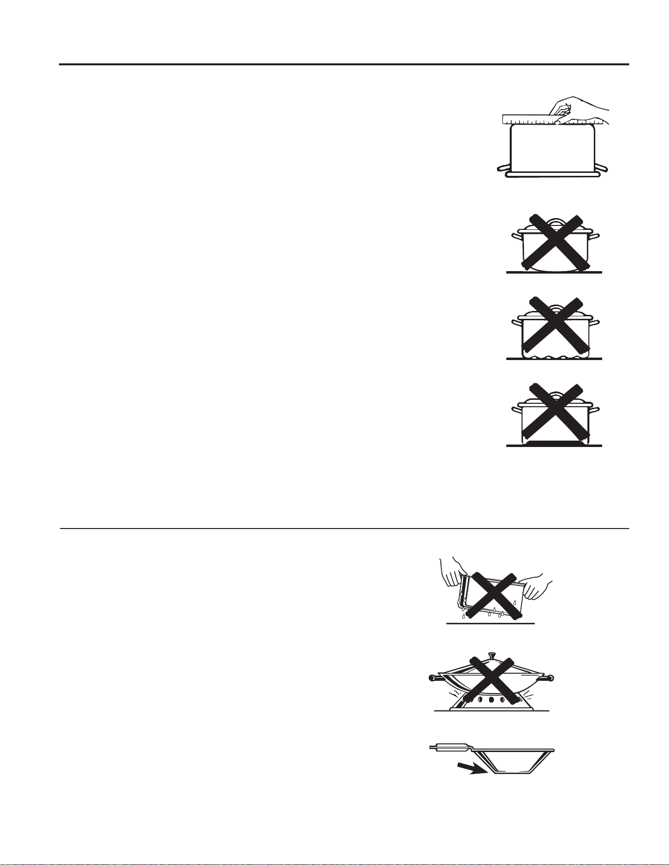
12
49-80773
Batterie de cuisine pour table de cuisson en verre radiant
UTILISATION DE LA CUISINIÈRE : Batterie de cuisine pour table de cuisson en verre radiant
Les renseignements qui suivent vous aideront à choisir un ustensile de cuisson offrant un bon rendement sur une surface
de cuisson en verre. Consultez l’encart pour connaître les ustensiles à utiliser sur les surfaces de cuisson à induction.
REMARQUE :2EVHUYH]WRXWHVOHVUHFRPPDQGDWLRQVGXIDEULFDQWGHO¶XVWHQVLOHGHFXLVVRQORUVTXHYRXVXWLOLVH]XQW\SH
quelconque d’ustensiles sur la surface de cuisson en vitrocéramique.
Acier inoxydable :
recommandé
Aluminum :
épais – recommandé
Bonne conductivité. Sur la surface de
cuisson, l’aluminium laisse parfois des
résidus qui ressemblent à des égratignures.
Ces résidus peuvent disparaître si la surface
HVWQHWWR\pHLPPpGLDWHPHQW(QUDLVRQGH
son point de fusion peu élevé, il n’est pas
recommandé d’utiliser l’aluminium mince.
Fond en cuivre :
recommandé
Le cuivre laisse des résidus qui ressemblent
à des égratignures. Vous pouvez les faire
GLVSDUDvWUHHQQHWWR\DQWLPPpGLDWHPHQWOD
surface de cuisson. Cependant, évitez de
faire chauffer ces ustensiles à vide. Le métal
surchauffé peut adhérer à la surface de
verre. Un ustensile dont le fond en cuivre a
été surchauffé laisse un résidu qui tachera
de façon permanente la surface de cuisson
si vous ne faites pas disparaître le résidu
immédiatement.
Émail vitrifié sur fonte :
recommandé si le fond de l’ustensile est
émaillé.
Émail vitrifié sur acier :
non recommandé
Si l’ustensile vide surchauffe, il pourrait
causer des dommages permanents à la
surface de cuisson en verre. L’émail vitrifié
peut fondre et adhérer à la surface de
cuisson en vitrocéramique.
Vitrocéramique :
non recommandée
5HQGHPHQWPpGLRFUHeJUDWLJQHUDODVXUIDFH
de cuisson.
Grès :
non recommandé
Rendement médiocre. Peut égratigner la
surface.
Fonte :
QRQUHFRPPDQGpH²jPRLQVTXHO¶XVWHQVLOH
soit spécialement conçu pour les surfaces de
cuisson en verre
)DLEOHFRQGXFWLYLWpHWDEVRUSWLRQOHQWHGHOD
FKDOHXUeJUDWLJQHUDODVXUIDFHGHFXLVVRQ
Vérifiez à l’aide d’une règle si le fond
de votre ustensile est plat.
Il n’est pas recommandé d’utiliser
un ustensile dont le fond est bombé,
incurvé, ondulé ou déformé.
Pour des résultats optimums
Ŷ 1HSODFH]TXHGHVXVWHQVLOHVGHFXLVVRQELHQVHFVVXUOHV
éléments chauffants. Ne déposez pas de couvercles sur
les éléments chauffants, particulièrement lorsqu’ls sont
mouillés.
Ŷ 1¶XWLOLVH]SDVGHZRNVVRXWHQXVDXPR\HQG¶XQDQQHDX
&HVZRNVQHFKDXIIHQWSDVVXUOHVpOpPHQWVGHODVXUIDFH
de cuisson en verre.
Ŷ 1RXVYRXVUHFRPPDQGRQVG¶XWLOLVHUVHXOHPHQWXQZRN
jIRQGSODW9RXVWURXYHUH]FHW\SHGHZRNFKH]YRWUH
GpWDLOODQWORFDO/HIRQGGXZRNGRLWDYRLUOHPrPHGLDPqWUH
que l’élément de surface pour permettre un bon contact.
Ŷ &HUWDLQHVWHFKQLTXHVGHFXLVVRQH[LJHQWXQXVWHQVLOH
spécial, par exemple un autocuiseur, une friteuse, etc.
Tous ces ustensiles doivent avoir un fond plat et être de
dimensions appropriées.
Ne placez pas d’ustensiles de cuisson mouillés
sur la surface de cuisson en verre.
N’utilisez pas sur la surface de cuisson en verre
un wok soutenu par un anneau.
Utilisez un wok à fond plat sur la surface de
cuisson en verre.
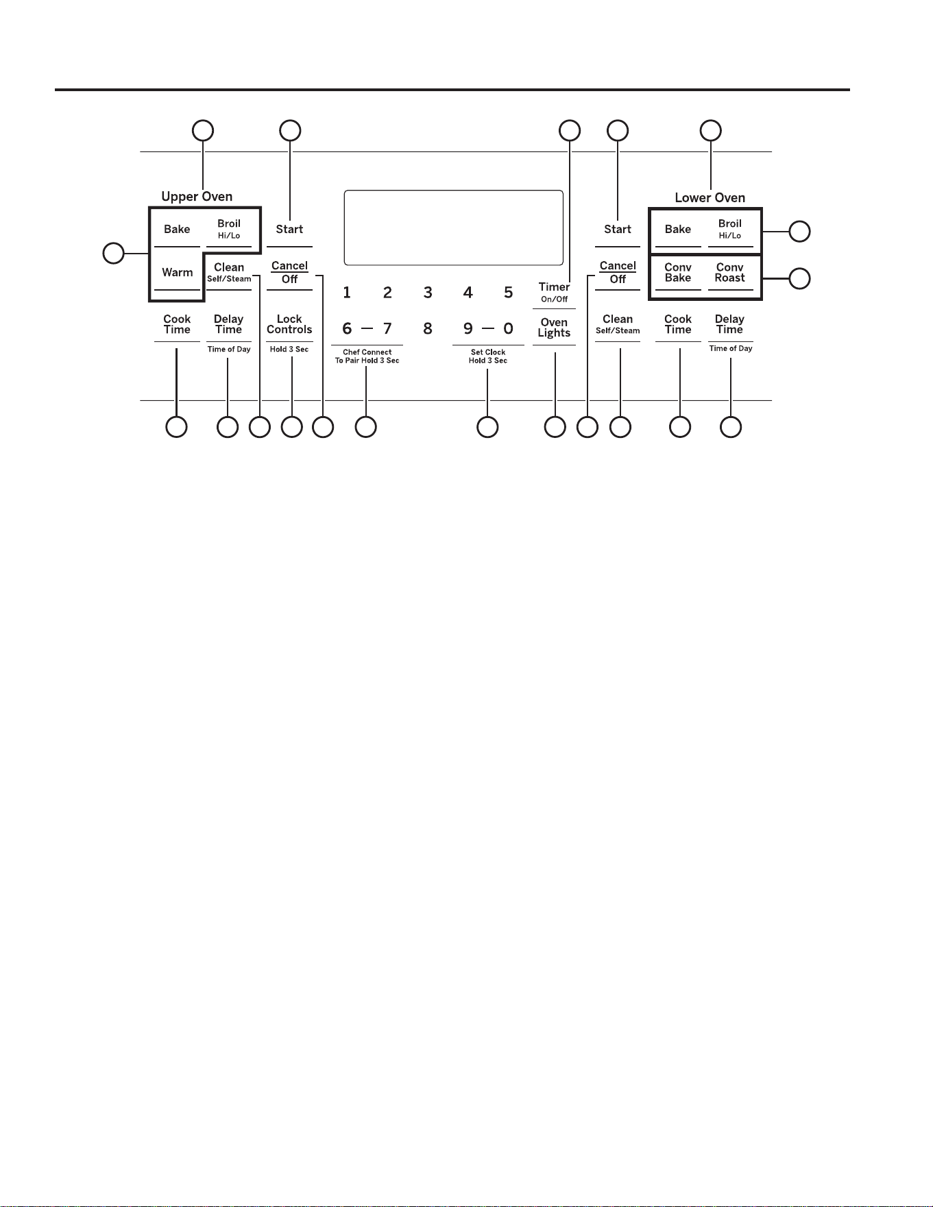
49-80773
13
1. Four supérieur et Four inférieur : Désigne lequel
des fours sera opéré par les commandes.
2. Convection Cooking Modes (Modes de
cuisson par convection) :
Les modes de cuisson par
FRQYHFWLRQDXJPHQWHQWODFLUFXODWLRQGDLUSRXUDPpOLRUHUOH
UHQGHPHQW/HW\SHGHEpQpILFHGpSHQGGXPRGH9RWUHIRXU
offre les modes de cuisson par convection suivants : Cuisson
SDUFRQYHFWLRQHW5{WLVVDJHSDUFRQYHFWLRQ9RLUODVHFWLRQ
des modes de cuisson pour de plus amples informations.
3. Traditional Cooking Modes (Modes de cuisson
traditionnels) :
Votre four offre les modes de cuisson
traditionnels suivants : Cuisson, Gril fort/faible et Chaud.
Voir la section des modes de cuisson pour de plus amples
informations.
4. Self Clean (Autonettoyage) : Consultez la section
1HWWR\DJHGXIRXUSRXUGHVUHQVHLJQHPHQWVLPSRUWDQWVVXU
OXWLOLVDWLRQGHFHPRGH
5. Start (Mise en marche) : 9RXVGHYH]DSSX\HUVXU
ce bouton pour démarrer toute fonction de cuisson, de
QHWWR\DJHRXGHPLQXWHULH
6. Cancel/Off (Annuler/Off) : Annule TOUTES les
opérations en cours sauf l’horloge et la minuterie.
7. Clock (Horloge) : 5qJOHOKHXUHGHOKRUORJHGXIRXU
$SSX\H]VXUSet Clock (Régler l'horloge) ou sur les touches
9 et 0 et maintenez la pression pendant 3 secondes. Utilisez
OHVWRXFKHVQXPpULTXHVSRXUSURJUDPPHUOKRUORJH$SSX\H]
sur Start (Mise en marche) pour enregistrer l’heure.
8. Timer (Minuterie) : )RQFWLRQQHFRPPHXQFRPSWHj
UHERXUV$SSX\H]VXUOHERXWRQTimer (Minuterie), puis sur
le pavé numérique pour programmer la durée en heures et
HQPLQXWHV$SSX\H]VXUOHERXWRQStart (Mise en marche).
6LOHIRXUHVWDOOXPpLOVpWHLQGUDXQHIRLVOHGpFRPSWH
WHUPLQp3RXUpWHLQGUHODPLQXWHULHDSSX\H]VXUOHERXWRQ
Timer (Minuterie).
9. Delay Time (Mise en marche différée) : Retarde
la mise en marche du four. Utilisez cette fonction pour régler
l’heure à laquelle vous désirez que le four se mette en marche.
$SSX\H]VXUODWRXFKHDelay Time (Mise en marche différée)
HWXWLOLVH]OHVWRXFKHVQXPpULTXHVSRXUUpJOHUOKHXUHGXMRXU
jODTXHOOHOHIRXUVDOOXPHUDSXLVDSSX\H]VXUStart (Mise en
marche). Programmez la température et le mode de cuisson
GpVLUpVSXLVDSSX\H]VXUStart (Mise en marche). Une durée
de cuisson peut également être programmée. Suivez les
LQVWUXFWLRQVVRXVODUXEULTXH&RRN7LPH7HPSVGHFXLVVRQ
SRXUUpJOHUFHWWHIRQFWLRQ2QSHXWOXWLOLVHUXQLTXHPHQWDYHF
%DNH&XLVVRQ&RQYHFWLRQ%DNH&XLVVRQSDUFRQYHFWLRQ
&RQYHFWLRQ5RDVW5{WLVVDJHjFRQYHFWLRQHW6HOI&OHDQ
$XWRQHWWR\DJH
REMARQUE : Lorsque vous utilisez la fonction de mise en
marche différée, les plats qui se gâtent rapidement tels que
le lait, les œufs, le poisson, les farces, la volaille et le porc
ne doivent pas être laissés à reposer pendant plus d’une
heure avant ou après la cuisson. La température de la pièce
favorise le développement de bactéries nocives. Assurez-vous
d’éteindre la lumière, car la lumière de l’ampoule accélèrera
également le développement de bactéries nocives.
10. Cook Time (Temps de cuisson) : )DLWOHGpFRPSWH
du temps de cuisson restant et éteint le four lorsque le
WHPSVGHFXLVVRQHVWWHUPLQp$SSX\H]VXUOHERXWRQ&RRN
7LPH7HPSVGHFXLVVRQXWLOLVH]OHSDYpQXPpULTXHSRXU
programmer un temps de cuisson en heures et en minutes,
SXLVDSSX\H]VXUStart (Mise en marche)2QSHXWOXWLOLVHU
XQLTXHPHQWDYHF7UDGLWLRQDO%DNH&XLVVRQWUDGLWLRQQHOOH
&RQYHFWLRQ%DNH&XLVVRQSDUFRQYHFWLRQHW5{WLVVDJHj
convection.
11. Oven Lights(s) (Lumière(s) du four) : Allume ou
éteint la ou les lampes dans les deux fours. Remarquez que
OHVODPSHVGHVGHX[IRXUVQHVDOOXPHQWSDVVLODSRUWHHVW
RXYHUWHSHQGDQWTXHODXWUHIRXUHVWHQPRGHGDXWRQHWWR\DJH
12. Lock Controls (Verrouillage des commandes) :
Verrouille les commandes de manière à ce que lorsqu’on
appuie sur les boutons, ceux-ci n’activent pas les commandes.
$SSX\H]VXUOHERXWRQLock Controls (Verrouillage des
commandes) pendant trois secondes pour verrouiller ou
déverrouiller les commandes. Cancel/Off (Annuler / Off) est
toujours actif, même lorsque les commandes sont verrouillées.
13. Chef Connect (Connexion du chef) : Appairez votre
cuisinière à une hotte ou un micro-ondes à hotte intégrée.
Pour appairer les appareils électroménagers, maintenez
OHVWRXFKHVHWSHQGDQWVHFRQGHV/¶LF{QH%OXHWRRWK
®
clignote pendant l’appairage et reste allumé une fois appairé.
&HWWHIRQFWLRQSHUPHWGHV\QFKURQLVHUOHVKRUORJHVGHVGHX[
appareils et d’allumer le ventilateur et les lumières à chaque
IRLVTX¶XQpOpPHQWHVWHQPDUFKH$SSX\H]jQRXYHDXSRXU
désactiver cette fonction et maintenez-la pendant 3 secondes
pour désappairer les appareils.
UTILISATION DE LA CUISINIÈRE : Commandes du four double
Commandes du four double
15 5 18
2
3
46 6
3
10 1011 12 13
9974

14
49-80773
UTILISATION DE LA CUISINIÈRE : Fonctions spéciales
Fonctions spéciales
Votre cuisinière est équipée de différentes fonctions spéciales.
Ŷ 3RXUPRGLILHUOHVUpJODJHVGHFHVIRQFWLRQVVSpFLDOHVDSSX\H]VLPXOWDQpPHQWVXUOHVWRXFKHVBake (cuisson) et Broil (gril)
SHQGDQWVHFRQGHV©2))6(WªV¶DIILFKHUDjO¶pFUDQ
Ŷ )DLWHVGpILOHUOHPHQX)RQFWLRQVVSpFLDOHVjO¶DLGHGHODWRXFKH8 pour descendre et de la touche 3 pour monter.
Ŷ 3RXUVpOHFWLRQQHUXQHIRQFWLRQjPRGLILHURXSRXUFRQILUPHUXQFKDQJHPHQWDSSX\H]VXUODWRXFKH0.
Ŷ 3RXUDQQXOHUXQFKDQJHPHQWHWUHYHQLUDXPHQX)RQFWLRQV6SpFLDOHVDSSX\H]VXUODWRXFKH6. Pour quitter le menu
)RQFWLRQV6SpFLDOHVDSSX\H]jQRXYHDXVXUODWRXFKH6.
Réglage de la température du four (OFFSEt)
Cette fonction permet de régler la température du four pour les
fonctions de cuisson et de cuisson par convection jusqu’à 35°
plus chaud ou plus froid. Utilisez cette fonction si vous pensez
que la température de votre four est trop élevée ou trop
basse et que vous souhaitez la modifier. Ce réglage affecte
OHVPRGHV%DNH&XLVVRQHW&RQYHFWLRQ%DNH&XLVVRQSDU
FRQYHFWLRQ$XFXQDXWUHPRGHGHFXLVVRQQ¶HVWPRGLILp
En utilisant les touches numériques pour naviguer comme
GpFULWFLGHVVXVVpOHFWLRQQH]©2))6(Wª8QQRPEUH
entre -35 et +35 va s’afficher. A l’aide des touches 8 ou 3,
augmentez ou réduisez la valeur de décalage. Enregistrez et
FRQILUPH]HQDSSX\DQWVXUODWRXFKH0.
Signal de fin de minuterie (End tonE)
Il s’agit de la tonalité qui signale la fin d’une minuterie. Cette
WRQDOLWpSHXWrWUHFRQWLQXH&RQE((3RXXQELSUpSpWLWLI
E((38QHWRQDOLWpFRQWLQXHVHUDpPLVHMXVTX¶jFHTXH
l’utilisateur appuie sur une touche.
Affichage de la température en degrés
Fahrenheit ou Celsius (dEg Unit)
Les commandes du four sont configurées pour une utilisation
DYHFGHVWHPSpUDWXUHVHQ)DKUHQKHLW)7RXWHIRLVFHOOHVFL
SHXYHQWrWUHDIILFKpHVHQGHJUpV&HOVLXV&
Configuration de l’horloge (Cloc cFg)
Cette fonctionnalité spécifie l’affiche de l’heure. Vous pouvez
FKRLVLUOHIRUPDWKHXUHV+RXKHXUHV+
Affichage de l’heure (Cloc diSP)
Cette fonction spécifie l’affichage de l’heure à l’écran ou non.
Cet affichage peut être activé ou désactivé.
Conversion automatique des températures
(Auto rEciPE)
/RUVGHO¶XWLOLVDWLRQGH&RQYHFWLRQ%DNH&XLVVRQSDU
&RQYHFWLRQODIRQFWLRQ$XWR5HFLSH&RQYHUVLRQFRQYHUVLRQ
DXWRPDWLTXHGHVWHPSpUDWXUHVYRXVSHUPHWGHFRQYHUWLU
automatiquement les températures de cuisson normales en
températures de cuisson par convection. Notez que cette
option ne convertit pas les temps de cuisson par convection
mais seulement les températures. Cette fonction peut être
activée ou désactivée.
Volume sonore (Sound)
Cette fonction permet de régler le volume de la sonnerie du
IRXUG¶XQYROXPHVRQRUHpOHYp+LPR\HQ5HJIDLEOHORHW
GpVDFWLYp2II/HIRXUpPHWWUDOHQRXYHDXYROXPHVRQRUHj
chaque fois que celui-ci est modifié.
Arrêt après 12 heures (2H ShutoFF)
Cette fonction éteint le four après 12 heures de fonctionnement
continu. Cette fonction peut être activée ou désactivée.
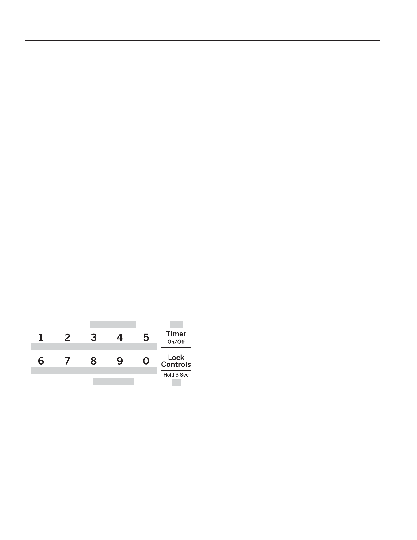
49-80773
15
Mode Sabbat
La fonction Sabbat est conforme aux normes énoncées par Star K. Certaines des règles seront remarquées par l’utilisateur,
notamment la désactivation des avertissements sonores, la désactivation des lampes de four et des délais d’environ 30 secondes
à une minute sur les changements d’affichage. Seule la cuisson continue ou la cuisson minutée est autorisé dans le mode Sabbat.
La cuisson en mode Sabbat se fait en deux étapes. Le mode Sabbat doit d’abord être sélectionné puis ensuite le mode Cuisson.
Sélection du mode Sabbat
$SSX\H]VLPXOWDQpPHQWVXUOHVWRXFKHVBake (Cuisson) et
Broil (Gril) et maintenez-les jusqu’à affichage du menu des
fonctions spéciales.
2. Utilisez les touches 3 ou 8 pour faire défiler les fonctions
VSpFLDOHVMXVTX¶jDIILFKDJHGXPRGH©6$EE$WKªSXLV
DSSX\H]VXUODWRXFKH0. Reportez-vous au diagramme
GDQVODVHFWLRQ)RQFWLRQV6SpFLDOHVSRXUYRLUO¶DWWULEXWLRQ
des touches numériques.
3. Utilisez les touches 3 ou 8 pour faire défiler les options
MXVTX¶jFHTXH©2QªV¶DIILFKHjO¶pFUDQSXLVDSSX\H]VXU
la touche 0 pour enregistrer cette sélection. Pour quitter
OHPHQX)RQFWLRQV6SpFLDOHVDSSX\H]VXUODWRXFKH6.
8QHSDUHQWKqVHXQLTXH©@ªV¶DIILFKHUDjO¾pFUDQLQGLTXDQW
que le mode Sabbat est programmé. L’heure ne sera pas
affichée. Il est alors possible de choisir la cuisson continue
ou la cuisson minutée.
Lancement d’une cuisson continue
$SSX\H]VXUODWRXFKHBake (Cuisson).
6LODWHPSpUDWXUHGpVLUpHHVW)DSSX\H]VXUStart
(Mise en marche). Si vous souhaitez une température de
cuisson différente, utilisez les touches 1 à 5 ou la touche
Timer (minuterie) pour sélectionner une température
GHFXLVVRQSUpUpJOpHSXLVDSSX\H]VXUStart (Mise en
marche). Reportez-vous au diagramme ci-dessous pour
connaitre la touche à utiliser pour la température de
cuisson désirée.
$XERXWG¶XQFRXUWGpODLXQHGHX[LqPHSDUHQWKqVH©@>ª
apparaîtra à l’écran indiquant que le four est en marche en
mode Cuisson.
Réglage de la température
$SSX\H]VXUODWRXFKHBake, utilisez les touches 1 à 5
ou la touche Timer (minuterie) pour sélectionner une
WHPSpUDWXUHGHFXLVVRQSUpUpJOpHSXLVDSSX\H]VXUStart
(Mise en marche).
2. Aucune information n’est donnée pendant le changement
de température, un thermomètre de four peut être utilisé
pour confirmer la modification.
Lancement d’une cuisson minutée
$SSX\H]VXUODWRXFKHBake (Cuisson).
6LODWHPSpUDWXUHVRXKDLWpHHVWGH)XWLOLVH]OHV
touches 6 à 0 ou la touche Lock controls (Verrouillage
des commandes) pour sélectionner un temps de cuisson.
Si vous souhaitez une température de cuisson différente
GH)XWLOLVH]OHVWRXFKHV1 à 5 ou la touche Timer
(minuterie) pour sélectionner une température de cuisson
SUpUpJOpHSXLVDSSX\H]VXUStart (Mise en marche).
Reportez-vous au diagramme ci-dessous pour connaitre
la touche à utiliser pour la température de cuisson désirée
ainsi que la durée de cuisson.
$SSX\HUVXUStart (marche).
$XERXWG¶XQFRXUWGpODLXQHGHX[LqPHSDUHQWKqVH©@>ª
DSSDUDvWUDjO¾pFUDQLQGLTXDQWTXHOHIRXUHVWHQPDUFKHHQ
mode Cuisson. Lorsque la durée de cuisson est écoulée, une
VHXOHSDUHQWKqVH©@ªV¶DIILFKHUDLQGLTXDQWTXHODFXLVVRQ
est terminée. Aucun avertissement sonore ne retentira à la
fin de la cuisson.
Désactivation du mode Sabbat
La désactivation du mode Sabbat devra se faire après la fin du
Sabbat.
$SSX\H]VXUCancel/Off (Annuler/Arrêt) pour mettre fin à
tout mode de cuisson en cours.
$SSX\H]VLPXOWDQpPHQWVXUOHVWRXFKHVBake (Cuisson) et
Broil (Gril) et maintenez-les jusqu’à affichage du menu des
fonctions spéciales.
3. Utilisez les touches 3 ou 8 pour faire défiler les fonctions
VSpFLDOHVMXVTX¶jDIILFKDJHGXPRGH©6DEEDWªSXLV
DSSX\H]VXUODWRXFKH0.
4. Utilisez les touches 3 ou 8 pour faire défiler les options
MXVTX¶jFHTXH©2))ªV¶DIILFKHjO¶pFUDQSXLVDSSX\H]VXU
la touche 0 pour enregistrer cette sélection. Pour quitter le
PHQX)RQFWLRQV6SpFLDOHVDSSX\H]VXUODWRXFKH 6.
En cas de panne d’électricité en mode Sabbat
En cas de panne d’électricité lorsque le four est en mode
sabbat, l’appareil revient au mode Sabbat lorsque l’électricité
est rétablie. Toutefois, le four restera éteint même s’il était en
cours de cuisson lorsque la panne est survenue.
UTILISATION DE LA CUISINIÈRE : Mode Sabbat
1 = 170° F, 2 = 200° F, 3 = 250° F, 4 = 300° F, 5 = 325° F, Minuterie = 400° F
6 = 2 heures, 7 = 2,5 heures, 8 = 3 heures, 9 = 3,5 heures,
0 = 4 heures, Verrouillage des commandes = 6 heures
7HPSpUDWXUHÛ) 400
7HPSVKHXUHV
6h
170
2h
200
2.5h
250
3h
300
3.5h
325
4h

16
49-80773
UTILISATION DE LA CUISINIÈRE : Grilles du four
/HVSRVLWLRQVUHFRPPDQGpHVSRXUOHVGLIIpUHQWVW\SHV
d’aliments sont fournies dans le Guide de cuisson. En réglant
la position des grilles, vous modifierez les résultats de la
cuisson. Par exemple, si vous préférez que le dessus de vos
gâteaux, muffins ou biscuits soit plus doré, mettez le plat sur
une position plus haute. Si vous trouvez que vos plats sont trop
cuits sur le dessus, mettez le plat sur une position plus basse.
Lorsque vous cuisinez avec plusieurs plats et sur plusieurs
grilles, assurez vous de laisser un espace d’au moins
FPòSRHQWUHOHVSODWVSRXUSHUPHWWUHjO¶DLUGHFLUFXOHU
adéquatement.
Votre four peut être équipé de grilles rétractables et de grilles
simples.
Pour éviter les brûlures, placez les grilles dans la position
désirée avant d’allumer le four.
Grilles rétractables
Lorsque vous placez ou retirez la vaisselle, tirez toujours
ODJULOOHSDUVRQUDLOVXSpULHXUDYDQWGHIDoRQjORXYULU
complètement.
Si les grilles rétractables sont difficiles à tirer, lubrifiez-les avec
le lubrifiant au graphite fourni avec votre four Retirez la grille
GXIRXUQHWWR\H]WRXWUpVLGXVXUOHVJOLVVLqUHVDYHFXQHVVXLH
tout, mélangez bien le lubrifiant, puis placez 4 petites gouttes
VXUOHVGHX[JOLVVLqUHVGXEDVGXF{WpGURLWHWJDXFKH2XYUH]
et fermez la grille plusieurs fois pour distribuer le lubrifiant
uniformément.
Pour commander davantage de lubrifiant au graphite, reportez-
vous à la section Assistance et accessoires de ce manuel.
Pour retirer une grille rétractable :
1. Assurez-vous que la grille est poussée dans le four jusqu’au
bout de façon à ce que les languettes transversales soient
sorties de leurs supports dans le four.
)DLWHVJOLVVHUODJULOOHYHUVYRXVMXVTX¶jODEXWpHSRVLWLRQ
G¶DUUrWVXUOHVXSSRUWGHODJULOOH
6DLVLVVH]IHUPHPHQWOHVGHX[F{WpVGXFDGUHGHODJULOOH
et la grille coulissante, inclinez la partie avant vers le haut,
puis retirez-la du four.
Pour replacer une grille rétractable :
6DLVLVVH]IHUPHPHQWOHVGHX[F{WpVGXFDGUHGHODJULOOHHW
la grille coulissante.
3ODFH]O¶H[WUpPLWpLQFXUYpHGHODJULOOHEXWpHVXUOHV
supports dans le four, soulevez l’avant de la grille et faites-
la entrer dans le four jusqu’à la butée.
Si les grilles rétractables sont difficiles à replacer ou à enlever,
appliquez de l’huile de cuisson sur les supports de grille à
l’aide d’un chiffon. N’appliquez pas d’huile sur les glissières.
Pour lubrifier le levier de dégagement :
Agitez la bouteille de lubrifiant et enduisez les pièces mobiles
des leviers de dégagement, comme indiqué.
Le nombre de hauteurs de grille varie d’un modèle à l’autre.
Rail supérieur
avant
Position avec grille dépliée
Attrapez la grille ici
Grilles du four

49-80773
17
UTILISATION DE LA CUISINIÈRE : Papier d’aluminium et doublures de four / Plats de cuisson
Plats de cuisson
Consignes pour les plats de cuisson
Le matériel, la finition et la dimension des plats de cuisson
influencent le résultat de la cuisson.
Les plats sombres et mats avec revêtement absorbent mieux
la chaleur que les plats légers et brillants. Les plats qui
absorbent mieux la chaleur peuvent donner une croûte plus
brune, plus croustillante et plus épaisse. Si vous utilisez des
plats de cuisson sombres avec revêtement, attendez-vous à ce
que l’aliment cuise plus rapidement que le temps minimal de
FXLVVRQ6LGHVUpVXOWDWVLQGpVLUDEOHVVRQWREWHQXVDYHFFHW\SH
GHYDLVVHOOHVRQJH]jUpGXLUHODWHPSpUDWXUHGH&)
la prochaine fois.
Les plats brillants peuvent permettront une cuisson plus
uniforme des pains et gâteaux.
Les plats de verre et de céramique chauffent lentement, mais
UHWLHQQHQWELHQODFKDOHXU&HVW\SHVGHSODWVIRQFWLRQQHQWELHQ
pour des mets tels que des tartes et des flans.
Les plats isothermes se réchauffent lentement et peuvent
réduire le brunissage du dessous.
Conservez les plats de cuisson propres pour qu’ils se
réchauffent uniformément.
MISE EN GARDE
:
Abstenez-vous d’utiliser tout type de papier ou de doublure dans le fond du
four. Ces articles peuvent emprisonner la chaleur ou fondre, endommageant le produit et causant un risque
de choc électrique, d’enfumage ou d’incendie. Les dommages résultant de l’usage inapproprié de ces articles
ne sont pas couverts par la garantie du produit.
Pour protéger des débordements, une feuille d’aluminium peut être placée sur une grille inférieure se trouvant à
plusieurs centimètres en dessous des aliments. N’utilisez pas plus de papier d’aluminium que nécessaire et ne
UHFRXYUH]MDPDLVODWRWDOLWpG¶XQHJULOOHDYHFOHSDSLHU/DLVVH]XQHGLVWDQFHG¶DXPRLQVFPSRHQWUHOH
papier et les parois du four pour permettre une bonne distribution de chaleur.
Papier d’aluminium et doublures de four

18
49-80773
Votre nouveau four offre toute une variété de modes de cuisson pour vous aider à obtenir les meilleurs résultats possibles. Ces
PRGHVVRQWGpFULWVFLGHVVRXV5HSRUWH]YRXVjODVHFWLRQGXJXLGHGHFXLVVRQSRXUGHVUHFRPPDQGDWLRQVVHORQOHVW\SHV
d’aliments. Rappelez-vous que votre nouveau four pourrait donner des résultats différents de ceux du four qu’il remplace.
Baking and Roasting Modes (Modes Cuisson et
Rôtissage)
6pOHFWLRQQH]XQPRGHSRXUFXLUHHWSRXUU{WLUVHORQOHW\SH
et la quantité de nourriture que vous préparez. Lors de la
préparation de gâteaux, biscuits et pâtisseries, préchauffez
toujours le four. Suivez les recommandations de la recette pour
le positionnement du plat de cuisson. Si aucune intruction n’est
donnée, placez le plat au centre du four.
Traditional Bake (Cuisson Traditionnelle)
Le mode de cuisson Cuisson Traditionnelle est conçu pour
la cuisson sur une grille seulement. Pour faire cuire le plat,
ce mode fait fonctionner surtout l’élément du bas, mais aussi
FHOXLGXKDXW3RXUXWLOLVHUFHPRGHDSSX\H]VXUODWRXFKH
Bake (Cuisson)HQWUH]XQHWHPSpUDWXUHSXLVDSSX\H]VXU
Start (Mise en marche). Il est généralement recommandé de
préchauffer le four lors de l’utilisation de ce mode.
Convection Bake (Cuisson par convection)
Le mode Cuisson à convection avec plusieurs grilles est
conçu pour une cuisson sur plusieurs grilles à la fois. Ce
PRGHXWLOLVHVXUWRXWODFKDOHXUGHOpOpPHQWDUULqUHPDLVDXVVL
celle des éléments supérieur et inférieur, de même que le
FLUFXODWLRQGDLUJpQpUpHSDUOHYHQWLODWHXUGHFRQYHFWLRQSRXU
DVVXUHUOXQLIRUPLWpGHFXLVVRQ9RWUHIRXUHVWGRWpGHOD
fonction Auto Recipe Conversion (Conversion automatique des
WHPSpUDWXUHVGHVRUWHTXLOQHVWSDVQpFHVVDLUHGHFRQYHUWLU
la température lorsque vous utilisez ce mode. La durée de
cuisson peut être légèrement supérieure avec plusieurs grilles
SDUUDSSRUWjXQHVHXOH3RXUXWLOLVHUFHPRGHDSSX\H]VXUOD
touche Convection Bake (Cuisson par convection), entrez
ODWHPSpUDWXUHSXLVDSSX\H]VXUStart. Utilisez toujours le
préchauffage avec ce mode.
Convection Roast (Rôtissage par convection)
/HPRGH5{WLVVDJHSDUFRQYHFWLRQHVWFRQoXSRXUU{WLUGHV
pièces de viande entières sur une seule grille. Ce mode
utilise la chaleur des éléments supérieur, inférieur et arrière
et du ventilateur de convection pour améliorer le brunissage
HWUpGXLUHOHWHPSVGHFXLVVRQ,OQHVWSDVQpFHVVDLUHGH
convertir la température. Dans ce mode, vérifiez les aliments
SOXVW{WTXHFHTXHVXJJqUHODUHFHWWHRXXWLOLVH]XQHVRQGH
WKHUPLTXH3RXUXWLOLVHUFHPRGHDSSX\H]VXUConvection
RoastHQWUH]ODWHPSpUDWXUHSXLVDSSX\H]VXUStart,OQHVW
pas nécessaire de préchauffer le four dans ce mode.
Broiling Modes (Modes Gril)
Le mode Gril est fonctionnel dans les deux fours. Pour un
PHLOOHXUUpVXOWDWOHIRXULQIpULHXUHVWUHFRPPDQGp6LORQ
XWLOLVHOHIRXUVXSpULHXUODSRUWHGRLWGHPHXUHU)(50e('DQV
le four inférieur, la porte doit demeurer OUVERTE. Surveillez
attentivement les aliments durant le gril. Usez de prudence
ORUVGXQJULOGDQVOHVSRVLWLRQVGHJULOOHVXSpULHXUHVSXLVTXH
ODSUR[LPLWpGHOpOpPHQWGHJULODFFURvWOHGpJDJHPHQWGH
IXPpHOpFODERXVVHPHQWHWODSRVVLELOLWpGHQIODPPHUOHJUDV
3RXUGHPHLOOHXUVUpVXOWDWVFHQWUH]OHVDOLPHQWVVRXVOpOpPHQW
chauffant du gril. Il n'est pas recommandé de cuire sous le
gril à la position de grille 7.
Autant que possible, utilisez des aliments qui se cuisent
normalement au gril. Ajustez la position de la grille selon
OLQWHQVLWpGHFKDOHXUTXLFRQYLHQWjODOLPHQW3ODFH]ODOLPHQW
SOXVSUqVGHOpOpPHQWVLYRXVVRXKDLWH]REWHQLUXQHVXUIDFH
JULOOpHDYHFOLQWpULHXUVDLJQDQW/HVDOLPHQWVSOXVpSDLVRX
qui doivent être cuits de part en part doivent se situer à plus
JUDQGHGLVWDQFHGHOpOpPHQWGHJULORXHQFRUHXWLOLVH]OD
fonction Broil Lo (Gril faible).
Broil Hi (Gril [Fort])
/HPRGH*ULO7UDGLWLRQQHO)RUWXWLOLVHODFKDOHXULQWHQVHGH
l’élément du haut pour faire saisir les plats. Utilisez le Gril
)RUWSRXUOHVPRUFHDX[GHYLDQGHSOXVPLQFHVRXSRXUOHV
plats que vous préférez moins cuits. Pour utiliser ce mode,
DSSX\H]VXUODWRXFKHBroil (Gril) puis sur Start (Mise en
marche). Il n’est pas nécessaire de préchauffer lors de
l’utilisation de ce mode.
Broil Lo (Gril [Faible])
/HPRGH*ULO7UDGLWLRQQHO)DLEOHXWLOLVHXQHFKDOHXUPRLQV
intense de l’élément du haut pour cuire les plats en profondeur
tout en produisant un brunissement de surface. Utilisez Gril
)DLEOHSRXUOHVFRXSHVGHYLDQGHSOXVpSDLVVHVRXSRXUOHV
plats que vous voulez faire cuire en profondeur. Pour utiliser
FHPRGHDSSX\H]VXUODWRXFKHBroil (Gril) deux fois, puis sur
Start (Mise en marche). Il n’est pas nécessaire de préchauffer
lorsque vous utilisez ce mode.
Warm (Maintien au chaud)
Le mode Maintien au chaud est conçu pour conserver les
plats chauds pendant un maximum de trois heures. Pour
XWLOLVHUFHPRGHDSSX\H]VXUWarm (Maintien au chaud),
puis sur Start (Mise en marche). Couvrez les plats qui ne
doivent pas se dessécher et ne couvrez pas ceux qui doivent
être croustillants. Il n’est pas nécessaire de préchauffer.
N’utilisez pas ce mode pour réchauffer un plat froid autre que
des craquelins, des croustilles ou des céréales sèches. Il n’est
pas recommandé de garder un plat chaud pendant plus de
deux heures.
UTILISATION DE LA CUISINIÈRE : Modes de cuisson
Modes de cuisson
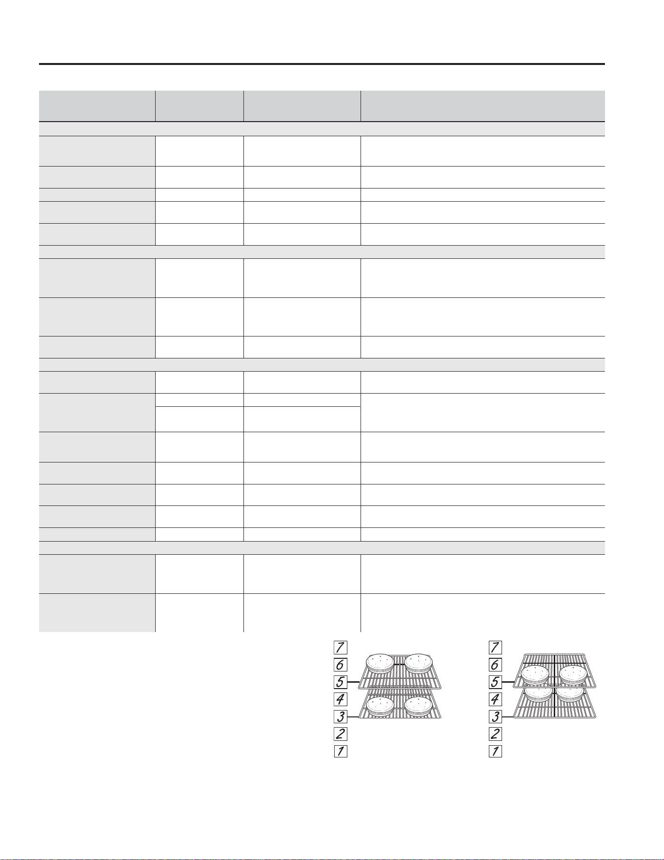
49-80773
19
TYPE DE NOURRITURE
MODES
RECOMMANDÉS
POSITIONS DE GRILLE
RECOMMANDÉES SUGGESTIONS ADDITIONNELLES
Boulangerie et pâtisserie
Gâteaux étagés, gâteaux à
feuilles, gâteaux Bundt, muffins,
pains rapides sur une seule grille
Cuisson 4 Utilisez des plats de cuisson brillants.
Gâteaux étagés* sur plusieurs
grilles
Cuisson
Cuisson par convection
3 et 5
Assurez-vous d’une circulation d’air adéquate
YRLULOOXVWUDWLRQFLGHVVRXV
Gâteau mousseline Cuisson 1 Utilisez des plats de cuisson brillants.
Biscuits, galettes, scones sur
une seule grille
Cuisson 4 Utilisez des plats de cuisson brillants.
Biscuits, galettes, scones sur
plusieurs grilles
Cuisson
Cuisson par convection
3 et 5
2, 4 et 6
Assurez-vous d’une circulation d’air adéquate.
Bœuf et porc
Hamburgers *ULO)RUW 6
Utilisez une lèchefrite; placez les aliments plus bas pour cuire davantage
OLQWpULHXURXREWHQLUXQHVXUIDFHPRLQVJULOOpH6XUYHLOOH]OHSODWGHSUqV
ORUVTXHYRXVOHIDLWHVJULOOHU3RXUXQPHLOOHXUUpVXOWDWFHQWUH]ODOLPHQWVRXV
OpOpPHQWGHJULO
6WHDNV&KRSV *ULO)RUW 6
Utilisez une lèchefrite; placez les aliments plus bas pour cuire davantage
OLQWpULHXURXREWHQLUXQHVXUIDFHPRLQVJULOOpH6XUYHLOOH]OHSODWGHSUqV
ORUVTXHYRXVOHIDLWHVJULOOHU3RXUXQPHLOOHXUUpVXOWDWFHQWUH]ODOLPHQWVRXV
OpOpPHQWGHJULO
5{WLV
Cuisson
5{WLVVDJHSDUFRQYHFWLRQ
3 ou 4
Utilisez un plat peu profond tel qu’une lèchefrite. Il n’est pas nécessaire de
préchauffer le four. Utilisez la sonde.
Volaille
Poulet entier
Cuisson
5{WLVVDJHSDUFRQYHFWLRQ
3 ou 4 Utilisez un plat peu profond tel qu’une lèchefrite.
Blancs, pattes et cuisses de
poulet non désossés
*ULO)RUW 2 6LO¶DOLPHQWHVWSDQpRXHQGXLWGHVDXFHpYLWH]OHPRGH*ULO)RUW)DLWHV
griller l’aliment avec la peau sur le bas d’abord, le cas échéant. Surveillez le
plat de près lorsque vous le faites griller. Pour un meilleur résultat, centrez
ODOLPHQWVRXVOpOpPHQWGHJULO
*ULO)DLEOH
Cuisson
2 ou 3
Blancs de poulet désossés
*ULO)DLEOH
Cuisson
2 ou 3
Placez le plat plus bas pour une meilleure cuisson et pour que le dessus
soit moins saisi, et placez-le plus haut pour qu’il soit plus saisi ou brunisse
GDYDQWDJH3RXUXQPHLOOHXUUpVXOWDWFHQWUH]ODOLPHQWVRXVOpOpPHQWGHJULO
Dinde entière
Cuisson
5{WLVVDJHSDUFRQYHFWLRQ
1 ou 2 Utilisez un plat peu profond tel qu’une lèchefrite.
Poitrine de dinde
Cuisson
5{WLVVDJHSDUFRQYHFWLRQ
2 ou 3 Utilisez un plat peu profond tel qu’une lèchefrite.
Poisson *ULO)DLEOH
>FPSRRXPRLQV@
>!FPSR@
Surveillez le plat de près lorsque vous le faites griller. Pour un meilleur
UpVXOWDWFHQWUH]ODOLPHQWVRXVOpOpPHQWGHJULO
Ragoûts Cuisson 3 ou 4
Aliments prêts-à-servir surgelés
Pizza, produits à base de
pommes de terre, croquettes
de poulet, hors d’œuvre sur une
seule grille
Cuisson 3 ou 4 Utilisez des plats de cuisson brillants.
Pizza, produits à base de
pommes de terre, croquettes
de poulet, hors d’œuvre sur
plusieurs grilles
Cuisson par convection 3 et 5 Utilisez des plats de cuisson brillants.
Guide de cuisson
UTILISATION DE LA CUISINIÈRE : Guide de cuisson
Cavité inférieure pour modèles à four double
Position de la grille pour la
fonction Traditional Bake
(Cuisson traditionnelle), gâteaux
à l’avant avec la grille en
position 3 et à l’arrière avec la
grille en position 5.
Position de la grille pour la
fonction Convection Bake
(Cuisson par convection),
gâteaux à l’arrière avec la grille
en position 3 et à l’avant avec la
grille en position 5.
* Lors de la cuisson de quatre gâteaux étagés à la fois en
mode cuisson traditionnelle, utilisez les grilles 3 et 5.
* Lors de la cuisson de quatre gâteaux étagés à la fois en
mode cuisson par convection, utilisez les grilles 3 et 5.
)DLWHVELHQFXLUHYRVDOLPHQWVSRXUYRXVSURWpJHUFRQWUH
les intoxications alimentaires. Les recommandations de
températures minimales pour la sécurité de vos aliments
sont données sur le site www.IsItDoneYet.gov. Assurez-
vous d’utiliser un thermomètre à aliments pour mesurer leur
température.
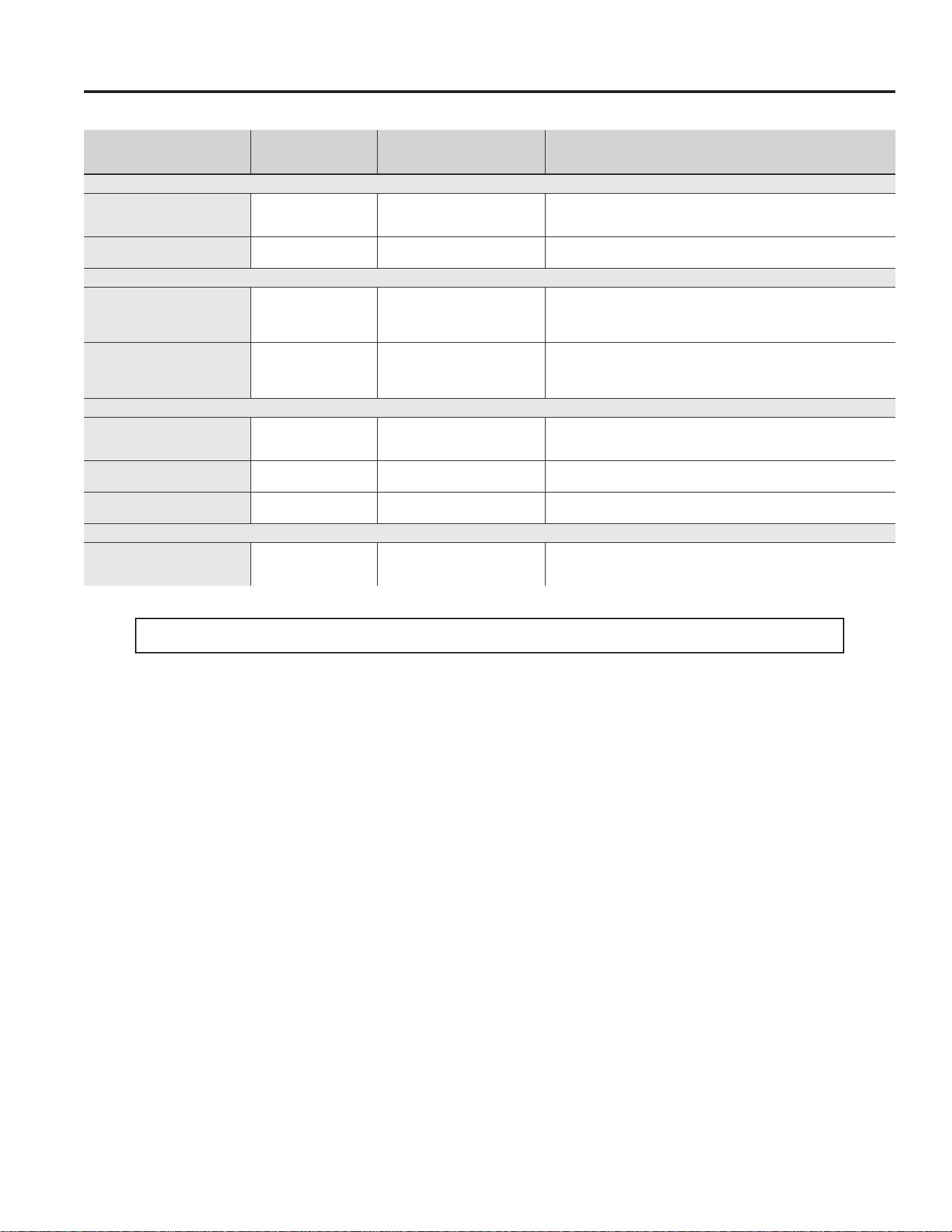
20
49-80773
TYPE DE NOURRITURE
MODES
RECOMMANDÉS
POSITIONS DE GRILLE
RECOMMANDÉES SUGGESTIONS ADDITIONNELLES
Boulangerie et pâtisserie
Gâteaux étagés, gâteaux à
feuilles, gâteaux Bundt, muffins,
pains rapides sur une seule grille
Cuisson 1 Utilisez des plats de cuisson brillants.
Biscuits, galettes, scones sur
une seule grille
Cuisson 1 Utilisez des plats de cuisson brillants.
Bœuf et porc
Hamburgers *ULO)RUW 1
Utilisez une lèchefrite; placez les aliments plus bas pour cuire davantage
OLQWpULHXURXREWHQLUXQHVXUIDFHPRLQVJULOOpH6XUYHLOOH]OHSODWGHSUqV
ORUVTXHYRXVOHIDLWHVJULOOHU3RXUXQPHLOOHXUUpVXOWDWFHQWUH]ODOLPHQWVRXV
OpOpPHQWGHJULO
6WHDNV&KRSV *ULO)RUW 1
Utilisez une lèchefrite; placez les aliments plus bas pour cuire davantage
OLQWpULHXURXREWHQLUXQHVXUIDFHPRLQVJULOOpH6XUYHLOOH]OHSODWGHSUqV
ORUVTXHYRXVOHIDLWHVJULOOHU3RXUXQPHLOOHXUUpVXOWDWFHQWUH]ODOLPHQWVRXV
OpOpPHQWGHJULO
Volaille
Blancs, pattes et cuisses de
poulet non désossés
*ULO)DLEOH
Cuisson
1
)DLWHVJULOOHUO¶DOLPHQWDYHFODSHDXVXUOHEDVG¶DERUGOHFDVpFKpDQW6XU-
veillez le plat de près lorsque vous le faites griller. Pour un meilleur résultat,
FHQWUH]ODOLPHQWVRXVOpOpPHQWGHJULO
Blancs de poulet désossés
*ULO)DLEOH
Cuisson
1 3RXUXQPHLOOHXUUpVXOWDWFHQWUH]ODOLPHQWVRXVOpOpPHQWGHJULO
Poisson *ULO)DLEOH
1
Surveillez le plat de près lorsque vous le faites griller. Pour un meilleur
UpVXOWDWFHQWUH]ODOLPHQWVRXVOpOpPHQWGHJULO
Aliments prêts-à-servir surgelés
Pizza, pommes de terre frites,
Tater Tots, croquettes de poulet,
hors d’œuvre sur une seule grille
Cuisson 1 Utilisez des plats de cuisson brillants.
Cavité inférieure pour modèles à four double
UTILISATION DE LA CUISINIÈRE : Guide de cuisson
Guide de cuisson (suite)
REMARQUE : Pour une meilleure cuisson au gril, le four inférieur est recommandé.

49-80773
21
Nettoyage de la cuisinière – Extérieur
ENTRETIEN ET NETTOYAGE : Nettoyage de la cuisinière – Extérieur
6LODFXLVLQLqUHHVWpORLJQpHGXPXUSRXUXQQHWWR\DJHXQH
maintenance ou quelque raison que ce soit, assurez-vous que le
dispositif antibasculement est correctement réenclenché lorsque
la cuisinière est remise contre le mur. Le non-respect de cet avertissement peut résulter en un basculement
de la cuisinière qui pourrait provoquer la mort ou des blessures corporelles.
AVERTISSEMENT
$YDQWGHQHWWR\HUXQHSLqFHTXHOFRQTXHGHODFXLVLQLqUHDVVXUH]YRXVTXHWRXWHVOHVFRPPDQGHVVRQWj2))HWTXHWRXWHVOHV
surfaces sont froides.
Boutons de commande
Les boutons de commande peuvent être retirés pour faciliter le
QHWWR\DJH$VVXUH]YRXVTXHOHVERXWRQVVRQWVXUODSRVLWLRQOFF
(Arrêt) et tirez-les en ligne droite pour les dégager de leur axe.
Les boutons peuvent être lavés au lave-vaisselle ou encore
PDQXHOOHPHQWjOHDXVDYRQQHXVH$VVXUH]YRXVTXH
OLQWpULHXUGHVERXWRQVHVWVHFDYDQWGHOHVUHSODFHU
Replacez les boutons dans la position OFF pour bien les
insérer.
Désactivation des touches numériques
Si vous le désirez, vous pouvez désactiverles touches
QXPpULTXHVDYDQWOHQHWWR\DJH
Reportez-vous à la section Verrouillage des commandes
dans la section Utilisation de l’horloge, de la minuterie et du
verrouillage des commandes du présent manuel.
1HWWR\H]OHVpFODERXVVXUHVDYHFXQFKLIIRQKXPLGH
9RXVSRXYH]pJDOHPHQWXWLOLVHUXQSURGXLWGHQHWWR\DJHSRXUYLWUHV
Enlevez la saleté plus importante avec de l’eau chaude
VDYRQQHXVH1¶XWLOLVH]DXFXQSURGXLWQHWWR\DQWDEUDVLI
'pYHUURXLOOH]OHVWRXFKHVQXPpULTXHVDSUqVOHQHWWR\DJH
Panneau de commandes
,OHVWERQGHQHWWR\HUOHSDQQHDXGHFRPPDQGHVDSUqVFKDTXH
utilisation. Lavez-le avec un savon doux et de l’eau, ou bien
avec du vinaigre et de l’eau, rincez avec de l’eau propre et
séchez avec un linge doux.
1¶XWLOLVH]SDVGHQHWWR\DQWVDEUDVLIVGHQHWWR\DQWVOLTXLGHV
puissants, de tampon à récurer en plastique, ni même de
SURGXLWVQHWWR\DQWVjIRXULOVHQGRPPDJHUDLHQWODILQLWLRQ
Extérieur du four
1¶XWLOLVH]SDVGHSURGXLWVQHWWR\DQWVjIRXUGHQHWWR\DQWV
DEUDVLIVGHQHWWR\DQWVOLTXLGHVSXLVVDQWVGHODLQHG¶DFLHUGH
WDPSRQVjUpFXUHUHQSODVWLTXHQLGHSRXGUHVQHWWR\DQWHVj
O¶LQWpULHXUQLVXUO¶H[WpULHXUGHYRWUHIRXU1HWWR\H]OHDYHFXQ
savon doux et de l’eau ou avec une solution de vinaigre et
d’eau. Rincez avec de l’eau propre et séchez avec un linge
GRX[/RUVTXHYRXVQHWWR\H]OHVVXUIDFHVDVVXUH]YRXVTX¶HOOHV
sont à la température de la pièce et qu’elles ne se trouvent pas
directement exposées au soleil.
Si une tache persiste sur la bordure de l’ouverture de la
YHQWLODWLRQGHODSRUWHXWLOLVH]XQSURGXLWQHWWR\DQWDEUDVLIGRX[HW
une éponge ou un tampon à récurer pour de meilleurs résultats.
Des débordements de marinades, de jus de fruits, de sauces
tomate et de bouillons contenant de l’acide pourraient entraîner
XQHGpFRORUDWLRQHWGRLYHQWrWUHQHWWR\pVLPPpGLDWHPHQW/DLVVH]
G¶DERUGOHVVXUIDFHVFKDXGHVUHIURLGLUSXLVQHWWR\H]HWULQFH]
Surfaces peintes
/HVVXUIDFHVSHLQWHVFRPSUHQQHQWOHVF{WpVGHODFXLVLQLqUHOHV
SRUWHVHWOHGHVVXVGXSDQQHDXGHFRPPDQGH1HWWR\H]FHVVXUIDFHV
avec de l’eau et du savon, ou avec une solution d’eau et de vinaigre.
1¶XWLOLVH]SDVGHSURGXLWVQHWWR\DQWVFRPPHUFLDX[SRXUOHIRXU
de poudres à récurer, de tampons en laine d’acier ou de produits
abrasifs sur les surfaces peintes.
Surfaces en acier inoxydable (sur certains modèles)
1¶XWLOLVH]SDVGHWDPSRQGHODLQHG¶DFLHUFHODSRXUUDLWUD\HUOD
surface.
3RXUQHWWR\HUODVXUIDFHG¶DFLHULQR[\GDEOHXWLOLVH]GHO¶HDX
FKDXGHHWVDYRQQHXVHRXXQSURGXLWQHWWR\DQWRXSURGXLWjSROLU
SRXUDFLHULQR[\GDEOH1HWWR\H]WRXMRXUVODVXUIDFHGDQVOHVHQV
GXJUDLQ6XLYH]OHVLQVWUXFWLRQVGXSURGXLWSRXUQHWWR\HUOHV
VXUIDFHVG¶DFLHULQR[\GDEOH
3RXUWRXWHVTXHVWLRQVFRQFHUQDQWO¶DFKDWGHSURGXLWVQHWWR\DQWV
\FRPSULVXQSURGXLWQHWWR\DQWRXXQSURGXLWjSROLUSRXUDSSDUHLO
pOHFWURPpQDJHUHQDFLHULQR[\GDEOHUHSRUWH]YRXVjDVHFWLRQ
Assistance et accessoires au début de ce manuel.
Surface de cuisson en émail vitrifié
L’émail vitrifié est un fini résistant, mais qui peut s’ébrécher
lors d’une utilisation négligente. Ce fini résiste aux acides.
Cependant, il ne faut pas laisser sur le fini des aliments acides
renversés (comme des jus de fruits, des produits à base de
WRPDWHRXGXYLQDLJUH
Si des aliments acides sont renversés sur la surface de cuisson
SHQGDQWTX¶HOOHHVWFKDXGHHVVX\H]OHVLPPpGLDWHPHQWDYHF
un essuie-tout ou un chiffon sec. Lorsque la surface a refroidi,
lavez-la avec de l’eau et du savon. Rincez à fond.
'DQVOHFDVGHVDXWUHVW\SHVG¶DOLPHQWVUHQYHUVpVFRPPHGHV
éclaboussures de graisse, lavez la surface avec de l’eau et du
VDYRQRXXQHSRXGUHQHWWR\DQWHORUVTXHODVXUIDFHDUHIURLGL
Rincez à fond. Polissez avec un chiffon sec.

22
49-80773
/LQWpULHXUGHYRWUHQRXYHDXIRXUSHXWrWUHQHWWR\pPDQXHOOHPHQWRXDXWRPDWLTXHPHQWDYHFODIRQFWLRQ$XWRQHWWR\DJH
Des débordements de marinades, de jus de fruits, de sauces tomate et de bouillons contenant de l’acide pourraient entraîner une
GpFRORUDWLRQHWGHYUDLHQWrWUHQHWWR\pVLPPpGLDWHPHQW/DLVVH]G¶DERUGOHVVXUIDFHVFKDXGHVUHIURLGLUSXLVQHWWR\H]HWULQFH]
Nettoyage manuel
1¶XWLOLVH]SDVGHSURGXLWVQHWWR\DQWVjIRXUGHQHWWR\DQWV
DEUDVLIVGHQHWWR\DQWVOLTXLGHVSXLVVDQWVGHODLQHG¶DFLHUGH
WDPSRQVjUpFXUHUQLGHSRXGUHVQHWWR\DQWHVjO¶LQWpULHXUGH
YRWUHIRXU1HWWR\H]OHDYHFXQVDYRQGRX[HWGHO¶HDXRXDYHF
une solution de vinaigre et d’eau. Rincez avec de l’eau propre
et séchez avec un linge doux. Assurez-vous que les surfaces
VRQWjWHPSpUDWXUHDPELDQWHORUVTXHYRXVOHVQHWWR\H]
Autonettoyage
$YDQWG¶XWLOLVHUO¶DXWRQHWWR\DJHOLVH]OHVLQVWUXFWLRQVHQPDWLqUH
GHVpFXULWpFRQFHUQDQWO¶DXWRQHWWR\DJHGXIRXU/¶DXWRQHWWR\DJH
XWLOLVHGHWUqVKDXWHVWHPSpUDWXUHVSRXUQHWWR\HUO¶LQWpULHXU
du four. La porte du four se verrouillera lorsque vous mettrez
HQPDUFKHFHWWHIRQFWLRQ$YDQWGHIDLUHIRQFWLRQQHUOHF\FOH
G¶DXWRQHWWR\DJHUHWLUH]ODJUDLVVHHWOHVVDOHWpVGXIRXU
Retirez également tous les objets sauf les grilles émaillées
IRQFpHV/HVJULOOHVEULOODQWHVRXDUJHQWpHVODVRQGHSRXU
la viande, et tout autre plat de cuisson ou objet doivent être
UHWLUpVGXIRXUDYDQWGHPHWWUHHQPDUFKHO¶DXWRQHWWR\DJH
)HUPH]ODSRUWH$SSX\H]VXUSelf Clean (Autonettoyage), et
XQHGXUpHG¶DXWRQHWWR\DJHSDUGpIDXWV¶DIILFKHUD&HOOHFLSHXW
rWUHSURJUDPPpHSRXUQ¶LPSRUWHTXHOOHGXUpHGHQHWWR\DJH
se trouvant entre 3 et 5 heures à l’aide du pavé numérique.
$SSX\H]VXUStart (Mise en marche). Dans le cas de fours
WUqVVDOHVXQHGXUpHGHQHWWR\DJHGHKHXUHVPD[LPXP
est recommandé. Si vous désirez utiliser la durée par défaut,
DSSX\H]VXUStart (Mise en marche) immédiatement après
DYRLUDSSX\pVXUSelf Clean (Autonettoyage.). Le four
V¶pWHLQGUDDXWRPDWLTXHPHQWORUVTXHOHF\FOHG¶DXWRQHWWR\DJH
sera terminé. La porte demeurera verrouillée jusqu’à temps que
OHIRXUDLWUHIURLGL$SUqVTXHOHIRXUDXUDUHIURLGLQHWWR\H]OHV
cendres qui pourraient encore se trouver dans le four.
Nous recommandons de ventiler votre cuisine en ouvrant une
fenêtre ou en actionnant un ventilateur ou la hotte durant le
SUHPLHUF\FOHGDXWRQHWWR\DJH
/DVDOHWpVXUOHFDGUHIURQWDOGHODFXLVLQLqUHHWjOH[WpULHXU
GXMRLQWGHSRUWHGRLWrWUHQHWWR\pHjODPDLQ3RXUFHV]RQHV
XWLOLVH]GHOHDXFKDXGHDYHFGHVWDPSRQVGHODLQHGDFLHU
VDYRQQHX[RXGHVQHWWR\DQWVGHW\SH6RIW6FUXE
®
. Rincez bien
jOHDXSURSUHSXLVDVVpFKH]
1HQHWWR\H]SDVOHMRLQW/DILEUHGHYHUUHGXMRLQWGHSRUWH
GXIRXUQHSHXWVXSSRUWHUODEUDVLRQ,OHVWHVVHQWLHOTXHOH
MRLQWGHPHXUHLQWDFW6LOSUpVHQWHGHVVLJQHVGXVXUHRX
GHIILORFKDJHUHPSODFH]OH
$VVXUH]YRXVTXHOHFRXYHUFOHGHODPSRXOHGHODODPSHGX
four est en place et que la lampe est éteinte.
IMPORTANT : Certains oiseaux sont très sensibles aux
YDSHXUVpPLVHVGXUDQWOHF\FOHGDXWRQHWWR\DJHGHVIRXUV
Déménagez les oiseaux dans une pièce bien ventilée.
Certains modèles :
Les unités de surface sont automatiquement désactivées
GXUDQWOHF\FOHGDXWRQHWWR\DJH$VVXUH]YRXVTXHWRXWHVOHV
FRPPDQGHVGHVXQLWpVGHVXUIDFHVRQWjODSRVLWLRQ2))
$UUrWHQWRXWWHPSVGXUDQWODXWRQHWWR\DJH7RXWHXQLWpTXL
HVWODLVVpHj210DUFKHGXUDQWODXWRQHWWR\DJHVHUDOOXPHUD
DXWRPDWLTXHPHQWXQHIRLVOHF\FOHWHUPLQpHWSUpVHQWHUDDLQVLXQ
ULVTXHVLOQ\DSDVGHVXUYHLOODQFH$WWHQGH]TXHODXWRQHWWR\DJH
soit terminé pour activer et utiliser les unités de surface.
ENTRETIEN ET NETTOYAGE : Nettoyage de la cuisinière - Intérieur
Nettoyage de la cuisinière - Intérieur
Grilles plates
Les grilles plates peuvent être laissées dans la cavité
GXUDQWODXWRQHWWR\DJHVLHOOHVVRQWpPDLOOpHVVDQV
EULOODQWRXrWUHODYpHVjOHDXVDYRQQHXVHFKDXGH
/HVJULOOHVSHXYHQWVDYpUHUSOXVGLIILFLOHVjJOLVVHUHQ
SDUWLFXOLHUDSUqVODXWRQHWWR\DJH(QGXLVH]XQOLQJHGRX[
RXXQHVVXLHWRXWGKXLOHYpJpWDOHHWIURWWH]HQOHVERUGV
gauche et droit.
Éléments chauffants du four
1HQHWWR\H]SDVO¶pOpPHQWGHFXLVVRQRXGHJULOODJH/D
saleté brûlera lorsque les éléments chaufferont.
3RXUQHWWR\HUODVROHGXIRXUORUVTXHOpOpPHQWGH
cuisson est exposé, soulevez ce dernier délicatement.
'DQVFHUWDLQVPRGqOHVOpOpPHQWGHFXLVVRQQHVWSDV
H[SRVpHWVHWURXYHVRXVODVROHGXIRXU1HWWR\H]OD
VROHGXIRXUjOHDXFKDXGHVDYRQQHXVH
Essuyez le surplus de saleté sur la sole du four.
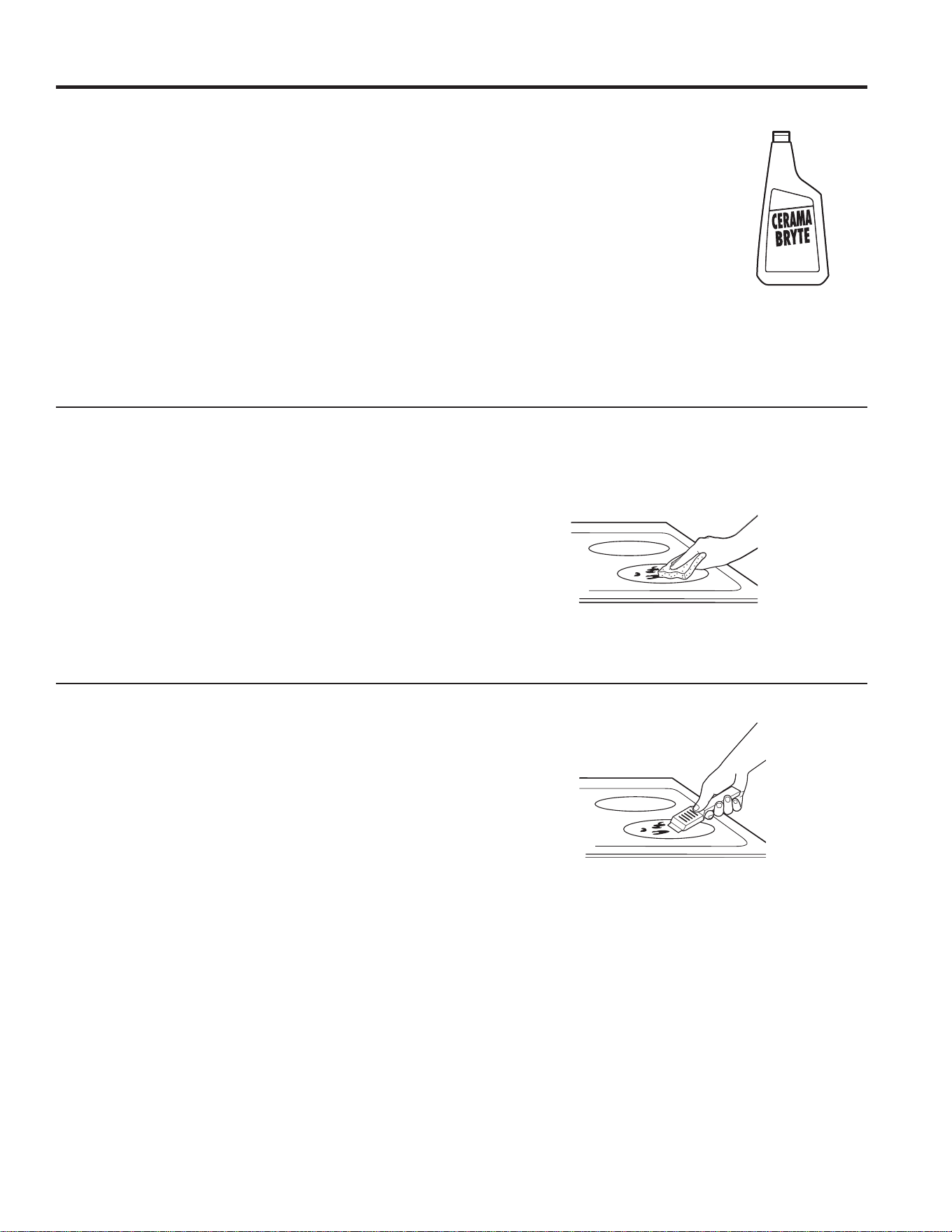
49-80773
23
Utilisez une éponge CERAMA BRYTE
®
pour
plaque de cuisson en vitrocéramique.
Nettoyage de la surface en vitrocéramique de la plaque de cuisson
Nettoyage normal quotidien
8WLOLVH]81,48(0(17ODFUqPHQHWWR\DQWH&(5$0$%5<7(
®
sur votre plaque de cuisson en vitrocéramique. Autres crèmes
peuvent être moins efficaces.
Pour entretenir et protéger votre plaque de cuisson en
vitrocéramique, conformez-vous aux instructions suivantes :
1. Avant d’utiliser votre plaque de cuisson pour la première
IRLVHQOHYH]OHVJULOOHVGHVEUOHXUVHWQHWWR\H]ODDYHFGHOD
FUqPHQHWWR\DQWH&(5$0$%5<7(
®
pour plaque de cuisson.
Cela vous aidera à la protéger et à la conserver propre.
2. Votre plaque de cuisson conservera son aspect neuf si vous
XWLOLVH]FKDTXHMRXUODFUqPHQHWWR\DQWH&(5$0$%5<7(
®
pour plaque de cuisson.
6HFRXH]ELHQOHIODFRQGHFUqPHQHWWR\DQWH9HUVH]
TXHOTXHVJRXWWHVGHFUqPHQHWWR\DQWH&(5$0$%5<7(
®
directement sur votre plaque de cuisson.
4. Utilisez une serviette en papier ou
une éponge CERAMA BRYTE
®
pour plaque de cuisson en
YLWURFpUDPLTXHDILQGHQHWWR\HUOD
surface de la plaque de cuisson.
5. Utilisez un linge sec ou une
serviette en papier pour enlever
WRXVOHVUpVLGXVGXQHWWR\DJH
Pas besoin de rincer.
REMARQUE : Vous devez faire bien
attention de NE PAS faire chauffer
la plaque de cuisson avant de la
QHWWR\HUFRPSOqWHPHQW
Résidus calcinés
REMARQUE : Vous pouvez ENDOMMAGER votre surface en
vitrocéramique si vous utilisez des éponges de récurage autres
que celles recommandées.
1. Laissez refroidir la plaque de cuisson.
2. Enlevez les grilles de brûleurs et versez quelques gouttes
GHFUqPHQHWWR\DQWH&(5$0$%5<7(
®
sur tous les
résidus calcinés.
3. À l’aide de l’éponge de récurage CERAMA BRYTE
®
pour
plaque de cuisson en vitrocéramique, frottez les résidus en
exerçant la pression nécessaire.
4. S’il reste des résidus, répétez les opérations indiquées
ci-dessus.
5. Pour mieux protéger après avoir enlevé les résidus, polissez
WRXWHODVXUIDFHDYHFODFUqPHQHWWR\DQWH&(5$0$%5<7(
®
et une serviette de papier
Résidus calcinés difficiles à enlever
1. Laissez refroidir la plaque de cuisson.
2. Enlevez les grilles de brûleurs. Tenez un grattoir à
lame simple à un angle d’environ 45º sur la surface de
vitrocéramique et raclez les résidus. Vous devrez exercer
de la pression sur le grattoir à lame pour les enlever.
3. Après avoir enlevé les résidus avec le grattoir à
ODPHYHUVH]TXHOTXHVJRXWWHVGHFUqPHQHWWR\DQWH
CERAMA BRYTE
®
pour plaque de cuisson sur les
résidus calcinés. Utilisez l’éponge CERAMA BRYTE
®
pour enlever les résidus restants.
)RUDGGLWLRQDOSURWHFWLRQDIWHUDOOUHVLGXHKDVEHHQ
removed, polish the entire surface with CERAMA
BRYTE
®
&HUDPLF&RRNWRS&OHDQHUDQGDSDSHUWRZHO
On peut se procurer le grattoir CERAMA BRYTE
®
pour plaque
de cuisson en vitrocéramique et tous les accessoires
recommandés dans nos Centres de pièces détachées.
Consultez les instructions dans la section « Comment
commander des pièces » à la page suivante.
REMARQUE : N’utilisez jamais une lame émoussée ou ébréchée.
ENTRETIEN ET NETTOYAGE : Nettoyage de la surface en vitrocéramique de la plaque de cuisson
Nettoyez votre plaque de
cuisson chaque fois qu’elle
est sale. Utilisez la crème
nettoyante CERAMA BRYTE
®
pour plaque de cuisson.
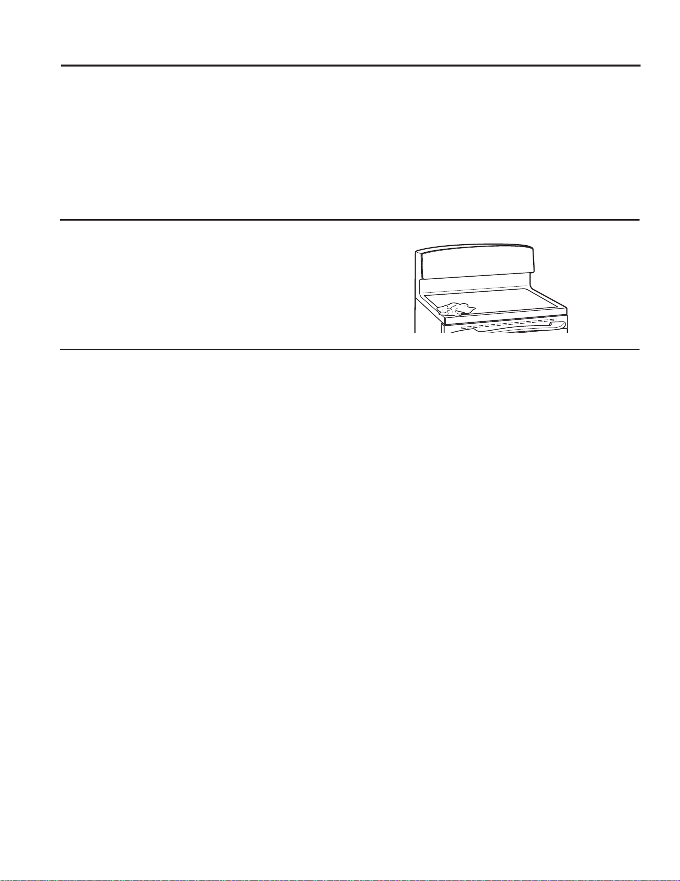
24
49-80773
ENTRETIEN ET NETTOYAGE : Nettoyage de la surface en vitrocéramique de la plaque de cuisson
Traces de métal et rayures
)DLWHVDWWHQWLRQGHQHSDVIDLUHJOLVVHUGHVXVWHQVLOHVGH
cuisine sur votre plaque de cuisson. Ils laisseront des
traces de métal sur la surface de vitrocéramique.
Vous pourrez enlever ces traces en appliquant la
FUqPHQHWWR\DQWH&(5$0$%5<7(
®
à l’aide de
l’éponge CERAMA BRYTE
®
pour plaque de cuisson en
vitrocéramique.
2. Si vous laissez des casseroles recouvertes d’une couche
d’aluminium ou de cuivre chauffer à sec, leur métal peut
laisser des traces noires sur la plaque de cuisson.
Vous devez enlever ces traces immédiatement, avant de
faire chauffer à nouveau la plaque de cuisson. Autrement,
les traces risquent de devenir permanentes.
REMARQUE : Vérifiez toujours le fond de vos casseroles pour
vous assurer qu’elles n’aient pas d’aspérités qui risquent de
UD\HUODSODTXHGHFXLVVRQ
Dommages causés par du sucre chaud ou des matières plastiques fondues
,OFRQYLHQWGHUHGRXEOHUGHSUXGHQFHORUVGXUHWUDLWGHVXEVWDQFHVWUqVFKDXGHVDILQGpYLWHUGHQGRPPDJHUHQSHUPDQHQFHOD
VXUIDFHYLWULILpH/HVDOLPHQWVVXFUpVUHQYHUVpVFRPPHOHVJHOpHVOHFDUDPHOOHVFRQILVHULHVHWOHVVLURSVRXOHSODVWLTXHIRQGX
SHXYHQWPDUTXHUYRWUHVXUIDFHGHFXLVVRQHQYHUUHGRPPDJHTXLQ¶HVWSDVFRXYHUWSDUODJDUDQWLHVDXIVLYRXVOHVHQOHYH]
LPPpGLDWHPHQWSHQGDQWTX¶LOVVRQWHQFRUHFKDXGV)DLWHVSDUWLFXOLqUHPHQWDWWHQWLRQORUVTXHYRXVHQOHYH]GHVVXEVWDQFHVFKDXGHV
Assurez-vous d’utiliser un grattoir dont la lame est neuve et bien aiguisée.
N’utilisez pas un grattoir dont la lame est émoussée ou ébréchée.
eWHLJQH]WRXVOHVEUOHXUVGHVXUIDFHHWDYHFGHVJDQWV
isolants, enlevez les ustensiles de cuisine chauds et les grilles.
2. Portez des gants de cuisine :
a. Utilisez un grattoir à lame simple (grattoir CERAMA
BRYTE
®
SRXUSODTXHGHFXLVVRQHQYLWURFpUDPLTXH
pour repousser les matières fondues sur une surface
froide de la plaque de cuisson.
b. Enlevez les matières fondues avec une serviette en papier.
3. Vous devez laisser toute matière fondue que vous n’avez
pas réussi à enlever jusqu’à ce que la plaque de cuisson
refroidisse complètement.
4. Ne réutilisez jamais la plaque de cuisson avant d’avoir
enlevé complètement les résidus.
REMARQUE : S’il s’est déjà formé sur votre plaque de cuisson
en vitrocéramique des creux ou des piqûres, vous devrez la
remplacer. Dans ce cas, vous devez appeler le service.
Joint d’étanchéité de la surface de cuisson
3RXUQHWWR\HUOHMRLQWG¶pWDQFKpLWpDXWRXUGHODVXUIDFHGH
cuisson, placez un chiffon mouillé sur le joint pendant quelques
PLQXWHVSXLVQHWWR\H]OHDYHFXQSURGXLWQHWWR\DQWQRQDEUDVLI
Nettoyage de la surface en vitrocéramique de la plaque de cuisson (suite)
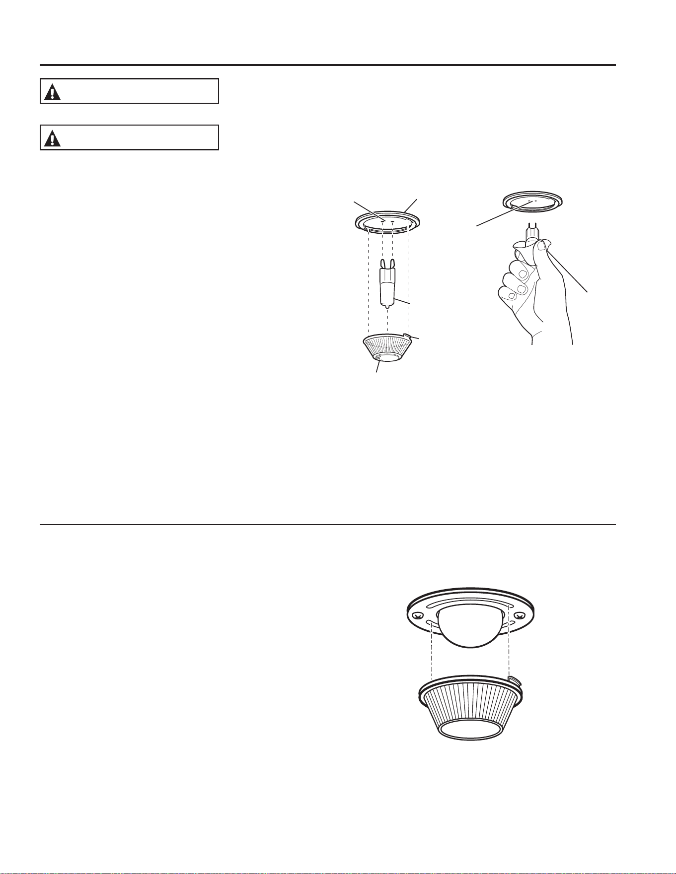
49-80773
25
DANGER DE CHOC ELECTRIQUE OU DE BRÛLURE : Avant de remplacer l’ampoule de
la lumière du four, coupez le courant qui alimente le four au fusible principal ou au tableau à
disjoncteurs. Le non-respect de cette directive pourrait entraîner un choc électrique ou une brûlure.
DDANGER DE BRÛLURE : La protection de verre et l’ampoule doivent être retirés après
refroidissement. Toucher le verre chaud à mains nues ou avec un linge humide peut causer
des brûlures.
AVERTISSEMENT
MISE EN GARDE
Entretien
ENTRETIEN ET NETTOYAGE : Entretien
Remplacement de la lumière du four
Pour enlever l’ampoule :
1. Tournez le capot en verre de 1/4 tour dans le sens
antihoraire jusqu’à ce que vous puissiez dégager les
languettes du capot des rainures de la douille. Vous aurez
une meilleure prise si vous portez des gants de latex.
2. À l’aide de gants ou d’un chiffon sec, enlevez l’ampoule en
tirant dessus.
Pour la remettre en place :
1. Utilisez une nouvelle ampoule à halogène de 120/130 V
d’une puissance maximale de 50 W. Remplacez l’ampoule
JULOOpHSDUXQHDXWUHGXPrPHW\SHTXHFHOOHTXHYRXVDYH]
enlevée. Assurez-vous que l’ampoule de rechange est de
9RX9HW121GH9
2. À l’aide de gants ou d’un chiffon sec, retirez l’ampoule de
son emballage. Ne touchez pas à l’ampoule avec vos
doigts. Le sébum de la peau causera des dommages à
l’ampoule et en réduira la durée de vie utile.
3. Poussez l’ampoule complètement dans la douille.
4. Insérez les languettes du capot dans les rainures de la
douille. Tournez le capot de 1/4 tour dans le sens horaire.
3RXUDPpOLRUHUO¶pFODLUDJHjO¶LQWpULHXUGXIRXUQHWWR\H]
souvent le capot en verre avec un linge humide. Effectuez
FHQHWWR\DJHXQLTXHPHQWORUVTXHOHIRXUDFRPSOqWHPHQW
refroidi.
5. Rétablissez l’alimentation électrique à la cuisinière.
Remplacement de l’ampoule du four (sur certains modèles)
Pour enlever l’ampoule :
1. Tournez le capot en verre de 1/4 tour dans le sens
antihoraire jusqu’à ce que vous puissiez dégager les
languettes du capot des rainures de la douille. Vous aurez
une meilleure prise si vous portez des gants de latex.
2. Retirez l’ampoule en la tournant dans le sens antihoraire.
Pour la remettre en place :
1. Remplacez l’ampoule par une nouvelle ampoule de 40
Watts pour appareil ménager. Insérez l’ampoule et tournez-
la dans le sens horaire jusqu’à ce qu’elle soit bien serrée.
2. Insérez les languettes du capot dans les rainures de la
douille. Tournez le capot de 1/4 tour dans le sens horaire.
3RXUDPpOLRUHUO¶pFODLUDJHjO¶LQWpULHXUGXIRXUQHWWR\H]
souvent le capot en verre avec un linge humide. Effectuez ce
QHWWR\DJHXQLTXHPHQWORUVTXHOHIRXUDFRPSOqWHPHQWUHIURLGL
3. Rétablissez l’alimentation électrique à la cuisinière.
Utilisez des
gants ou
un chiffon
Boîtier de
la lampe
Ampoule G9
Douille
Languette
Capot en verre
Boîtier de la lampe
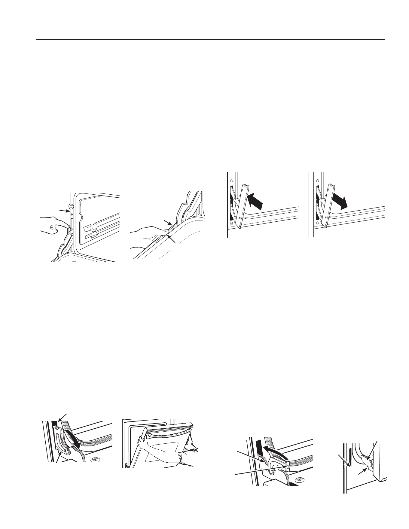
26
49-80773
Pousser les verrous de charnière
vers le haut pour verrouiller
Verrou de
charnière
Bras de la
charnière
Cran
Fond du
gond
Bras de la
charnière
Porte de four amovible
/DSRUWHHVWWUqVORXUGH)DLWHVDWWHQWLRQORUVTXHYRXVODUHWLUH]HWODVRXOHYH]
Ne soulevez pas la porte par sa poignée.
Pour retirer la porte :
1. Ouvrez la porte complètement.
2. Tirez les verrous de charnière vers le bas du cadre
de la porte, jusqu’à ce que ceux-ci soient en position
déverrouillée. Un outil tel qu’un tournevis à lame plate
pourrait être nécessaire.
(PSRLJQH]IHUPHPHQWOHVGHX[F{WpVGHODSRUWHHQKDXW
)HUPH]ODSRUWHMXVTX¶jFHTX¶HOOHVRLWHQSRVLWLRQSRXUrWUH
HQOHYpH/DSRUWHGHYUDLWrWUHRXYHUWHG¶HQYLURQFPSR
et sans aucune obstruction.
5. Soulevez la porte vers le haut et vers l’extérieur jusqu’à ce
que les deux charnières soient sorties de leurs gonds.
Pour replacer la porte :
(PSRLJQH]IHUPHPHQWOHVGHX[F{WpVGHODSRUWHHQKDXW
(QFRPPHQoDQWGXF{WpJDXFKHODSRUWHSODFpHGDQV
le même angle que celui dans lequel elle a été enlevée,
placez le cran de la charnière au fond des gonds.
L’encoche du bras de la charnière doit être placée bien au
IRQGGHVRQJRQG5pSpWH]GHO¶DXWUHF{Wp
3. Ouvrir complètement la porte. Si elle ne s’ouvre pas
complètement, c’est que le cran n’est pas placé bien au
fond de son gond.
4. Poussez les verrous de charnière vers le haut, contre le
cadre extérieur de la cavité du four, jusqu’à temps qu’ils
soient en position verrouillée.
)HUPH]ODSRUWHGXIRXU
Porte amovible du four supérieur
Pour enlever la porte :
1. Ouvrez complètement la porte.
2. Relevez le verrou de la charnière vers le cadre du four
jusqu’à ce qu’il bloque.
3. Refermez la porte à 45 degrés (vous sentirez le cran d’arrêt
GHODSRUWH/HYHUURXGHODFKDUQLqUHHQWUHUDHQFRQWDFW
avec le cadre du four.
'HVGHX[F{WpVGHODSRUWHDSSX\H]VXUOHERXWRQGH
déclenchement de chaque charnière.
5. Soulevez la porte pour la dégager des charnières.
6. Tirez légèrement sur les bras de charnière pour atténuer la
pression sur les languettes de blocage.
7. Poussez sur les verrous de charnière jusqu’à ce qu’ils
s’appuient sur la charnière.
8. Poussez sur les charnières vers l’appareil pour les fermer.
Pour remettre la porte en place :
1. Tirez sur les charnières afin de les ouvrir complètement.
2. Relevez le verrou de la charnière vers le cadre du four
jusqu’à ce qu’il bloque.
3. Les charnières sont dégagées lorsqu’elles forment un angle
de 45 degrés. Les verrous des charnières entreront en
contact avec le cadre du four.
)DLWHVJOLVVHUODSRUWHVXUOHVFKDUQLqUHV$VVXUH]YRXV
que les boutons reviennent à leur position initiale.
5. Ouvrez complètement la porte.
6. Poussez sur les verrous de charnière jusqu’à ce qu’ils
s’appuient sur la charnière.
7. Refermez la porte du four.
Position pour enlever
Verrou de charnière
Gond
Tirer les verrous de charnière vers
le bas pour déverrouiller
ENTRETIEN ET NETTOYAGE : Entretien
Entretien (suite)
Cadre
du four
Cadre de
la porte
Boutons de
déclenchement
Abaisser
Relever

49-80773
27
Remarques

28
49-80773
Remarques

49-80773
29
Remarques
30
49-80773
Économisez du temps et de l’argent! Consultez les tableaux des pages suivantes, et vous n’aurez peut-être pas à appeler le dépanneur.
Problème Cause possible Que faire?
Les éléments d e surface
n’assurent pas une ébullition
continue ou une cuisson
suffisamment rapide
Utilisation d’un ustensile de
cuisson inadéquat.
Utilisez des ustensiles dont le fond est absolument plat et dont le
diamètre est similaire à celui de l’élément de surface choisi.
Dans certaines régions, la tension
peut être plus basse.
Mettez un couvercle sur l’ustensile de cuisson utilisé jusqu’à ce que
vous obteniez la température désirée.
Les éléments de surface
ne fonctionnent pas
correctement
Un fusible peut être grillé ou un
disjoncteur déclenché dans le
panneau de distribution électrique
de votre résidence.
Remplacez le fusible ou réenclenchez le disjoncteur.
Commandes mal réglées. Assurez-vous de régler le bouton de commande orrespondant à
l’élément que vous désirez utiliser.
La lueur rougeâtre des
éléments de surface disparaît
lorsque l’élément est réglé à
une température plus basse
L’élément est encore en marche et
chaud.
Ce phénomène est normal.
Égratignures (ressemblant
à des fissures) sur la
surface de cuisson en verre
Utilisation de méthodes de
nettoyage non appropriées.
Il n’est pas possible de faire disparaître les égratignures. Les fines
égratignures deviendront moins apparentes avec le temps et les
QHWWR\DJHV
Utilisation d’ustensiles de cuisson à
fond rugueux ou grosses particules
(sel ou sable) entre l’ustensile et la
surface de cuisson. Vous avez fait
glisser un ustensile de cuisson sur
la surface de cuisson.
3RXUpYLWHUOHVpJUDWLJQXUHVVXLYH]OHVSURFpGXUHVGHQHWWR\DJH
recommandées. Avant de les utiliser, assurez-vous que le fond des
ustensiles de cuisson est propre et lisse.
Décoloration sur la surface
de cuisson
Aliments renversés non nettoyés
avant l’utilisation suivante.
5HSRUWH]YRXVjODVHFWLRQ1HWWR\DJHGHODVXUIDFHGHFXLVVRQHQ
verre.
Surface brûlante sur un modèle
dont la surface de cuisson est de
couleur claire.
Ce phénomène est normal. La surface de cuisson peut paraître
décolorée quand elle est brûlante. Cette décoloration est temporaire
et disparaît à mesure que le verre refroidit.
Plastique fondu sur la
surface de cuisson
Un article en plastique est entré en
contact avec la surface de cuisson
brûlante.
Reportez-vous à la section Surface en verre – possibilité de
GRPPDJHVSHUPDQHQWVVRXV1HWWR\DJHGHODVXUIDFHGH
cuisson en verre.
Petits trous (ou marques)
sur la surface de cuisson
Mélange sucré chaud renversé sur
la surface de cuisson.
Appelez un technicien qualifié pour faire remplacer la surface de
cuisson.
Fonctionnement cyclique
fréquent des éléments de
surface
Utilisation d’un ustensile de
cuisson non approprié.
3RXUUpGXLUHDXPLQLPXPFHIRQFWLRQQHPHQWF\FOLTXHQ¶XWLOLVH]TXH
des ustensiles de cuisson à fond plat.
Mon nouveau four ne cuit
pas aussi bien que mon
ancien four. Y aurait-il un
problème avec les réglages
de température ?
Votre nouveau four a un système
de cuisson différent de votre ancien
four; par conséquent, il pourrait
avoir un fonctionnement différent
de celui de votre ancien four.
Pour les quelques premières utilisations, respectez les temps de
FXLVVRQLQGLTXpVSDUYRVUHFHWWHV6LYRXVFUR\H]HQFRUHTXHYRWUH
nouveau four est trop chaud ou trop froid, vous pouvez ajuster la
température vous-même pour atteindre votre préférence spécifique de
cuisson. REMARQUE : Cet ajustement a un effet sur les températures
GHVPRGHV%DNH&XLVVRQHW&RQYHFWLRQ%DNH&XLVVRQSDU
FRQYHFWLRQOHVPRGHV&RQYHFWLRQ5RDVW5{WLVVDJHSDUFRQYHFWLRQ
%URLO*ULORX&OHDQ1HWWR\DJHQHVHURQWSDVDIIHFWpV
Les aliments ne sont pas
cuits correctement.
Les commandes du four ne sont
pas bien réglées.
Reportez-vous à la section Modes de cuisson.
Les positions de grille ne sont pas
correctes, ou les grilles ne sont
pas de niveau.
Reportez-vous à la section Modes de cuisson et Guide de cuisson.
Les plats de cuisson utilisés ne
conviennent pas ou ne sont pas de
la bonne taille.
Reportez-vous à la section Plats de cuisson.
Le réglage de température doit être
modifié.
5HSRUWH]YRXVjODVHFWLRQ)RQFWLRQVVSpFLDOHV
Substitution d’ingrédient La substitution d’ingrédients peut influencer le résultat de la recette.
Conseils de dépannage... Avant d’appeler un dépanneur
CONSEILS DE DÉPANNAGE
49-80773
31
Problème Cause possible Que faire?
Les aliments ne grillent pas
correctement.
Les commandes du four ne sont pas bien
programmées.
Assurez-vous de sélectionner le mode Gril approprié.
Les positions de grille utilisées ne sont pas les
bonnes.
Reportez-vous au Guide de cuisson pour obtenir des
suggestions concernant l’emplacement de la grille.
Les aliments sont cuits dans un plat chaud. Assurez-vous que les plats de cuisson sont froids.
Les plats de cuisson ne sont pas appropriés pour
faire griller.
Utilisez un plat conçu expressément pour faire griller des
aliments, tel qu’une lèchefrite.
Le papier d’aluminium utilisé dans la lèchefrite et
sur la grille n’est pas de la bonne taille et n’est
pas découpé tel qu’il a été recommandé de le
faire.
Si vous utilisez du papier d’aluminium, conformez-vous au plat
utilisé.
Dans certaines régions, le voltage pourrait être
moins élevé.
Préchauffez l’élément pendant 10 minutes.
La température du four est
trop élevée ou trop basse.
La température du four doit être ajustée. 5HSRUWH]YRXVjODVHFWLRQ)RQFWLRQVVSpFLDOHV
Le four ne fonctionne pas ou
semble ne pas fonctionner.
Un fusible de votre maison pourrait avoir sauté,
ou le disjoncteur pourrait être ouvert.
Remplacez le fusible ou le disjoncteur.
Les commandes du four ne sont pas bien
réglées.
Reportez-vous à la section Utilisation du four.
Le four est en mode Sabbat. Vérifiez que le four n’est pas en mode Sabbat. Reportez-vous à
ODVHFWLRQ)RQFWLRQVVSpFLDOHV
Sons de crépitement ou
d’éclatement.
Ces sons proviennent du métal qui chauffe et qui
refroidit durant les fonctions tant de cuisson que
de nettoyage.
C’est normal.
Pourquoi ma cuisinière
émet-elle un « clic » lorsque
j’utilise le four?
Votre cuisinière active et désactive en alternance
les relais des éléments de chauffage afin de
maintenir la température du four.
C’est normal.
L’horloge et la minuterie ne
fonctionnent pas
Un fusible peut être grillé ou un disjoncteur
déclenché dans le panneau de distribution
électrique de votre résidence.
Remplacez le fusible ou réenclenchez le disjoncteur.
La fiche de la cuisinière n’est pas bien branchée
dans la prise de courant. Plug on range is not
completely inserted in the electrical outlet.
Assurez-vous que la fiche est bien branchée dans une prise de
courant sous tension, adéquatement mise à la terre.
Commandes du four mal réglées. Reportez-vous à la section Utilisation de l’horloge, de la
minuterie et du verrouillage des commandes.
La porte du four est travers La porte est mal placée. Comme la porte du four est amovible, il arrive parfois qu’elle
VRLWPDOUpLQVWDOOpH3RXUUHGUHVVHUODSRUWHDSSX\H]VXUOHFRLQ
supérieur de la porte.
La lumière du four ne
fonctionne pas.
L’ampoule est desserrée ou défectueuse. Resserrez ou remplacez l’ampoule.
La lumière du clavier est grillée. Appelez le service à la clientèle.
Le four ne s’autonettoie pas. La température est trop élevée pour démarrer une
opération d’autonettoyage.
Laissez refroidir le four et reprogrammez les commandes.
Les commandes du four ne sont pas bien
réglées..
5HSRUWH]YRXVjDVHFWLRQ1HWWR\DJHGXIRXU
Fumée excessive durant le
cycle de nettoyage.
Saleté ou graisse excessive. $SSX\H]VXUOHERXWRQCancel/Off (Annuler/Off). Ouvrez
les fenêtres pour faire sortir la fumée. Attendez que le signal
lumineux VERROUILLÉV¶pWHLJQH1HWWR\H]OHVUpVLGXVGH
VDOHWpHWUHSUHQH]OHF\FOHGHQHWWR\DJH
Fumée excessive durant la
fonction Gril.
Le plat est trop près de l’élément. Placez la grille et le plat plus bas.
La porte du four ne s’ouvre
pas après un cycle de
nettoyage..
Le four est trop chaud. Laissez le four refroidir jusqu’à la température nécessaire pour
qu’il se déverrouille.
Le four n’est pas propre
après un cycle de nettoyage..
Les commandes du four ne sont pas bien
réglées.
5HSRUWH]YRXVjODVHFWLRQ1HWWR\HUOHIRXU
Le four était très sale. 1HWWR\H]OHVGpERUGHPHQWVYROXPLQHX[DYDQWGHPHWWUHHQPDUFKH
XQF\FOHGHQHWWR\DJH/HVIRXUVWUqVVDOHVSRXUUDLHQWGHYRLUVXELU
XQDXWUHDXWRQHWWR\DJHRXXQDXWRQHWWR\DJHSOXVORQJ
Le signal « LOCK DOOR »
(porte verrouillée) clignote
sur l’écran d’affichage.
Le cycle autonettoyage a été sélectionné mais la
porte n’est pas fermée.
)HUPH]ODSRUWHGXIRXU
Le signal DOOR LOCK
(porte verrouillée) est allumé
lorsque vous voulez cuisiner
La porte du four est verrouillée parce que la
température dans le four n’est pas descendue
sous la température de verrouillage.
$SSX\H]VXUODWRXFKHClear/Off. Laissez le four refroidir.
CONSEILS DE DÉPANNAGE
Troubleshooting tips (Cont.) ... Before you call for service
32
49-80773
Problème Cause possible Que faire?
« F » ainsi qu’un nombre
ou une autre lettre clignote
à l’écran d’affichage.
Vous avez un code d’erreur de fonction. $SSX\H]VXUOHERXWRQCancel/Off (Annuler/Off). Laissez le four
refroidir pendant une heure. Remettez-le en marche.
Si le code de fonction se répète. Débranchez tout le courant qui alimente le four pendant au moins
30 secondes, puis rebranchez-le. Si le code d’erreur de fonction se
répète, appelez le service à la clientèle.
L’écran n’affiche rien. Un fusible dans votre maison pourrait
avoir sauté ou un disjoncteur pourrait
s’être ouvert..
Remplacez le fusible ou réenclenchez le disjoncteur.
L’horloge est éteinte. 5HSRUWH]YRXVjODVHFWLRQ)RQFWLRQVVSpFLDOHV
Le four est en mode Sabbat. Vérifiez que le four n’est pas en mode Sabbat. Reportez-vous à la
VHFWLRQ)RQFWLRQVVSpFLDOHV
Panne de courant,
l’horloge clignote.
Panne de courant ou surtension Reprogrammez l’horloge. Si le four était en utilisation, vous devez
OHUHSURJUDPPHUHQDSSX\DQWVXUOHERXWRQCancel/Off (Annuler/
Off), reprogrammer l’horloge puis reprogrammer la fonction de
cuisson.
Une odeur de brûlé
ou d’huile émane de
l’ouverture de ventilation.
C’est normal pour un nouveau four; cette
odeur disparaîtra avec le temps.
3RXUDFFpOpUHUOHSURFHVVXVSURJUDPPH]XQF\FOHG¶DXWRQHWWR\DJH
pour un minimum de 3 heures. Reportez-vous à la section
1HWWR\DJHGXIRXU
Forte odeur Une odeur venant de l’isolation posée
autour de l’intérieur du four est normale
pour les quelques premières utilisations du
four.
Cette odeur est temporaire et s’en ira après plusieurs utilisations ou
DSUqVXQDXWRQHWWR\DJH
Bruit de ventilateur
(sur certains modèles)
Un ventilateur de convection peut se mettre
en marche et s’arrêter automatiquement.
Ce phénomène est normal. Ce ventilateur est conçu pour tourner
dans les deux sens, en faisant une pause entre les deux, pour
maximiser l’uniformité de la cuisson. Le ventilateur de convection
IRQFWLRQQHSHQGDQWOHSUpFKDXIIDJHG¶XQF\FOHGHFXLVVRQ,O
s’arrêtera lorsque le four aura atteint la température préréglée. Ce
phénomène est normal.
Un ventilateur de refroidissement
peut se mettre en marche et s’arrêter
automatiquement.
Ce phénomène est normal. Ce ventilateur est conçu pour se mettre
en marche et s’arrêter pour refroidir des pièces internes. Il peut
FRQWLQXHUGHIRQFWLRQQHUPrPHDSUqVTXHYRXVD\H]pWHLQWOHIRXU
La vitre de la porte de
mon four semble être
teintée ou présenter une
couleur arc-en-ciel. Est-elle
défectueuse?
Non. La vitre intérieure du four est recouverte
d’une barrière conçue pour refléter la chaleur
vers le four pour empêcher la perte de
chaleur et pour garder la porte extérieure
froide lorsque le four est en fonction.
C’est normal. Sous un certain éclairage ou certains angles, vous
pourriez voir cette teinte ou cette couleur arc-en-ciel.
Parfois, le four prend
plus de temps pour se
réchauffer à une même
température.
Plat de cuisson ou nourriture dans le four Le plat de cuisson ou l’aliment se trouvant dans le four influencera
le temps nécessaire pour préchauffer le four. Retirez les objets à
l’intérieur pour réduire le temps nécessaire pour préchauffer.
Nombre de grilles dans le four Ajouter d’autres grilles fera en sorte que le four tardera davantage
à se préchauffer. Enlevez des grilles.
Différents modes de cuisson Les différents modes de cuisson utilisent chacun différentes
méthodes pour préchauffer le four. Certains modes prendront plus
GHWHPSVTXHG¶DXWUHVFj&XLVVRQSDUFRQYHFWLRQ
L’écran d’affichage
clignote
Panne de courant. Réglez de nouveau l’horloge.
Impossibilité d’afficher le
message «SF» à l’écran
Vous n’avez pas appuyé correctement sur
les touches.
,OIDXWDSSX\HUVLPXOWDQpPHQWVXUOHVWRXFKHVBroil Hi/Lo et Bake
pendant 3 secondes.
Un signal sonore se fait
entendre après avoir entré
une durée de cuisson
ou une heure de mise en
marche
Vous avez oublié d’entrer une température
de cuisson ou une durée de nettoyage.
$SSX\H]VXUODWRXFKHBake et entrez la température désirée ou
DSSX\H]VXUODWRXFKHSelf CleanHWHQWUH]ODGXUpHGHQHWWR\DJH
désirée.
Les grilles du four ne
glissent pas facilement
d’autonettoyage
Les grilles lustrées de couleur argent ont
été nettoyées au programme
Appliquez une petite quantité d’huile végétale sur un essuie-tout et
HVVX\H]OHVERUGVGHVJULOOHVDYHFO¶HVVXLHWRXW1HYDSRULVH]SDV
d’enduit végétal Pam
®
RXDXWUHVW\SHVGHOXEULILDQW
De la vapeur s’échappe par
l’évent
Lors d’une cuisson, il est normal que de la
vapeur s’échappe par l’évent du four. Plus
le nombre de grilles utilisées ou la quantité
d’aliments dans le four augmente, plus il y
a de la vapeur visible qui s’échappe.
C’est normal.
Conseils de dépannage... Avant d’appeler un dépanneur
CONSEILS DE DÉPANNAGE
